EP1569256A1 - Interrupteur de mise à la terre isolé pour sectionneurs isolés au gaz - Google Patents
Interrupteur de mise à la terre isolé pour sectionneurs isolés au gaz Download PDFInfo
- Publication number
- EP1569256A1 EP1569256A1 EP04405117A EP04405117A EP1569256A1 EP 1569256 A1 EP1569256 A1 EP 1569256A1 EP 04405117 A EP04405117 A EP 04405117A EP 04405117 A EP04405117 A EP 04405117A EP 1569256 A1 EP1569256 A1 EP 1569256A1
- Authority
- EP
- European Patent Office
- Prior art keywords
- earth
- housing
- contact
- flange
- measuring
- Prior art date
- Legal status (The legal status is an assumption and is not a legal conclusion. Google has not performed a legal analysis and makes no representation as to the accuracy of the status listed.)
- Granted
Links
Images


Classifications
-
- H—ELECTRICITY
- H01—ELECTRIC ELEMENTS
- H01H—ELECTRIC SWITCHES; RELAYS; SELECTORS; EMERGENCY PROTECTIVE DEVICES
- H01H33/00—High-tension or heavy-current switches with arc-extinguishing or arc-preventing means
- H01H33/02—Details
-
- H—ELECTRICITY
- H01—ELECTRIC ELEMENTS
- H01H—ELECTRIC SWITCHES; RELAYS; SELECTORS; EMERGENCY PROTECTIVE DEVICES
- H01H31/00—Air-break switches for high tension without arc-extinguishing or arc-preventing means
- H01H31/003—Earthing switches
Definitions
- the invention relates to the field of high voltage engineering, in particular electrical insulation and Connection technology for gas-insulated at ground potential Switchgear (GIS). It starts from a grounding device and a gas-insulated switchgear according to Preamble of the independent claims.
- GIS ground potential Switchgear
- Earth-switching devices in existing gas-insulated switchgear can be implemented as so-called "isolated earth electrodes" become.
- Such an isolated earth electrode is in the article of Okabe et al., "Serialization of Standard Gas Insulated Switchgear”, Hitachi Review Vol. 51 (2002), No. 5.
- the invention takes this state of the art Reference.
- GIS Gas-insulated switchgear
- the earthing contact is electrically from the GIS housing isolated from this led out and can outside shorted to the GIS housing via a contact clip become.
- EP 1 068 624 B1 also discloses a combined Disconnector / earthing switch.
- the earth contact designed as pinartiges contact piece, which on a Contact carrier is seated, which in turn at one by the GIS housing wall guided to the outside, against the GIS housing wall electrically insulated bolt is held.
- the object of the present invention is to provide an improved insulated earth electrode for gas-insulated switchgear specify. This object is achieved by the Features of the independent claims solved.
- the invention consists in a grounding device, in particular for gas-insulated, encapsulated high-voltage switchgear, comprising an encapsulation-side ground contact, an internal earthing contact and a grounding housing, which serves to receive an earth drive and that an earth mounting side of the gas-insulated switchgear with a GIS housing of the gas-insulated switchgear mechanically is connected, wherein an electrically insulated measuring electrode for electrical contacting of the encapsulation side Earth contact is present from the outside, where Furthermore, the encapsulation-side ground contact, the measuring electrode and the earth housing together on the earth mounting side are arranged and the encapsulation-side ground contact and the measuring electrode opposite the earth housing and the GIS housing are electrically isolated.
- the earth electrode is therefore complete, including drive and measuring tap, on only one side or mounting surface of the GIS encapsulation arranged and accessible from this side.
- the earth housing serves to accommodate components of the earthing switchgear and typically houses the earth drive.
- Of the earth contacts is at least one movable earthing contact.
- the measuring electrode or the measuring tap through the GIS housing or the earth housing electrically isolated to the outside and / or by an externally mountable earth connection can be short-circuited with the GIS housing and / or the grounding housing.
- the measuring tap is therefore for electrical Contacting and execution of the encapsulation side Earth contact through the GIS housing or earthing housing permanently installed. This causes only minor Additional costs. This eliminates a special, expensive Isolierflansch with intricately cast-in bolts on both sides, the former possibly between GIS housing and earth housing had to be mounted for measurement purposes.
- the before different building types of isolated and non-isolated Erders are now structurally executable. If all Erder isolated, measurements can also be made different places in the GIS plant and therefore with better meaningfulness.
- the embodiment according to claim 4 has the advantage that it does not matter for the purposes of the invention, whether the encapsulation-side ground contact a movable Earth contact or a fixed contact.
- the Invention applicable to any type of earth independently of whether the mobile earth contact from the inside to the outside, d. H. towards the enclosure wall, or from outside is movable inside.
- the embodiment according to claim 5 has the advantage that the earth electrode as a whole hangs on a single flange, which at the same time carries the earthing housing (support flange) and a has separate access for the measuring electrode (measuring flange). This arrangement is particularly space-saving.
- the claims 6-7 relate to embodiments of a Earth electrode and in particular Schnellerder, in which the flange and the measuring flange orthogonal to each other are.
- Claim 10 relates to an electrical switchgear comprising a Erdschalt réelle as described above and with the there mentioned advantages.
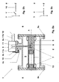
- Fig. 1a shows a conventional non-insulated earth switching device 1 in an encapsulated gas-insulated switchgear 13.
- the housing 2 of the gas-insulated switchgear 13 encloses a gas space 9, which is preferably filled with SF 6 gas under some bar pressure.
- the Erderanbau 3 with its grounding housing 3a is attached to the GIS housing 2 via a mounting flange 4a.
- a movable earthing contact pin 5 is moved from the Erderantrieb 11 typically arranged in the earth electrode 3a along a drive movement 11a to the earth-fixed contact 6 in order to earth active parts 7 of the encapsulated gas-insulated switchgear 13.
- the pin 5 In normal operation of the switchgear 13, the pin 5 is withdrawn and the active parts 7 are under high voltage and / or carry operating current or short-circuit current.
- the active parts or conductors 7 are held by insulators 8, in particular support insulators 8 and bulkhead insulators 8, in the gas-filled interior 9 of the enclosure 2.
- the insulators 8 are in turn supported on the GIS encapsulation 2 by means of insulator flanges 8a.
- the longitudinal axis of the non-insulated Schnellerders 1 is designated A.
- Fig. 1b shows the circuit diagram of the non-isolated Switching device 1, after which the ground potential through the GIS housing 2 is defined and the entire device 1 together the earth housing 3a and the earth contacts 5, 6 in the grounding case electrically connected to ground potential.
- the earth casing 3a or the earth attachment 3 are additional via drive lines 12 and / or drive linkage 11b electrically connected to the outside world.
- FIG. 2a shows the earth electrode or fast line 1 'as before, however, in an isolated embodiment.
- the Erderanbau 3 with the grounding housing 3a by an insulating Intermediate flange 4b of the GIS housing 2 electrically isolated.
- the intermediate flange 4b bridged by a grounding strap 10, which is the earth housing 3a shorts with the GIS housing 2.
- the hanger 10 removed and the earth housing 3a serves as a Measuring electrode. That's why other electrical connections must be made to the earth housing 3a, in particular electrical Connections 12 and drive linkage 11b, are removed. This is awkward and labor intensive.
- Fig. 2b and Fig. 2c show the circuit diagram of the isolated Earth switching device 1 'in normal operation or in electrical Measurements of active parts 7 of the switchgear 13 in earthed condition. When removed bracket 10 so is the Grounding canceled and the measurements can be performed become.
- earth switchgear implementations 1, 1 ' is the moving contact 5 from the outside, d. H. from the enclosure 2, inwards to the active parts 7 moved.
- the earthing contact 6 is typically in the active parts 7 integrated in the inner tube.
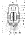
- Fig. 3 shows a first and Fig. 4 shows a second embodiment the invention.
- the earth switch device 1 '' comprises an encapsulation-side ground contact 50, 51; 500, an internal earthing contact 60; 600 and a terrestrial housing 3a, which serves to receive the earth drive 11 and that on an earth mounting side 3b of the gas-insulated Switchgear 13 with the GIS housing 2 of the gas-insulated Switchgear 13 is mechanically connected, wherein a electrically insulated measuring electrode 52, 520 for electrical Contacting the encapsulation-side ground contact 50, 51; 500 is present from the outside.
- the encapsulation-side ground contact 50, 51; 500, the measuring electrode 52, 520 and the earth housing 3a together on the same ground mounting side 3b are arranged and are the encapsulation-side ground contact 50, 51; 500 and the measuring electrode 52, 520 opposite to the Earth case 3a and the GIS housing 2 electrically isolated.
- the following example embodiments are given.
- the encapsulation-side ground contact 50, 51; 500 and the measuring electrode 52, 520 opposite the earth drive 11 and / or to any existing electrical connections 12 for the earth drive 11 and / or towards neighboring phases, especially opposite an optionally existing drive linkage 11b Neighbor phases, electrically isolated.
- the earth connection 53, 530 on the measuring flange 42 or the earth housing 3a mountable ground connection bracket 53, 530 in the mounted state, the measuring electrode 52, 520 with the measuring flange 42 or the earth housing 3a electrically short-circuits. Electrical measurements are therefore simplified because except the ground connection 53, 530 no other interrupted electrical contacts to the earth housing 3a Need to become. Due to the easy handling of the Personal protection improved during the measurements.
- An earth assembly 3 enclosed by the earth housing 3 a can via a combined support and measuring flange 40; 41, 42; 400 on the ground mounting side 3b with the GIS housing 2 mechanically be connected.
- the earthing housing is preferred 3a, the combined support and measuring flange 40; 41, 42; 400 and the GIS housing 2 electrically connected to each other.
- the earth housing 3 a is therefore always directly with the GIS housing 2 connected and requires no insulating Intermediate flange.
- the encapsulation-side ground contact is a movable earthing contact 50, 51 and includes an earthing contact pin 50, by a Isolierschaltstange 51 from Earth drive 11 electrically isolated and through the Isolierschaltstange 51 is drivable. Isolated is executed So only the pin 50 and not the entire earth electrode 1''. The internal earthing contact is then as earth contact 60 executed.
- the combined support and measuring flange 40; 41, 42 may, as shown, a along of the movable earthing contact 50, 51 extended support flange 41 and one laterally attached to the support flange 41 Measuring flange 42 for receiving and carrying the measuring electrode 52 have.
- the lateral access to the isolated executed contact pin 50 is connected to a ground connection 53 electrically conductive with the GIS housing 2 connected.
- This connection 53 is mounted in normal operation and creates contact between the ground contact pin 50 and GIS housing 2 and optionally earth housing 3a. For measurements where a measurement signal is applied to the earth contact system applied or tapped on this, only the earth connection 53 needs to be removed without that further work on the drive 11, its wiring 12 or his rod 11b are necessary.
- a dielectric insulation 44 for the electrical insulation of the measuring flange 42 of the measuring electrode 52 may be present.
- Fig. 4 shows a second embodiment of the invention. This is exemplary using a combined isolator / earthing contactor 1 '' shown.
- the separation section 14 and the grounding path 15 are here by way of example in series arranged.
- the active parts 7 include next the conductors 7, a holder 7a, the optional formed as a power connection 7a along the transverse axis B. and a shield 7b for the movable contact tube 113 of the isolator / earthmover. Again, it's an earth-drive 11, a movable earth contact 600 and a Earth contact 500 available.
- the example here shown combined disconnector / earth drive includes besides the motor unit 11, a drive shaft 110, an insulating shaft 111 and a spindle 112 for driving the contact tube 113 and in particular the movable earthing contact 600th
- the encapsulation-side ground contact formed as a stationary contact 500, which by a dielectric Insulation 540 from the earth housing 3a electrically is isolated, and the internal ground contact is the movable earthing contact tube 600.
- the movable earthing contact 600 and the earth contact 500 are in the gas space. 9 the gas-insulated switchgear 13 is arranged.
- the earth contact 500 typically has a contact system 501, z. B. coil springs o. ⁇ ., On.
- the earth switching device 1 ' is particularly suitable for gas-insulated Medium or high voltage switchgear 13 suitable. claimed is also a switchgear 13 with such Earth switching device 1 '.
Landscapes
- Gas-Insulated Switchgears (AREA)
- Driving Mechanisms And Operating Circuits Of Arc-Extinguishing High-Tension Switches (AREA)
Priority Applications (7)
| Application Number | Priority Date | Filing Date | Title |
|---|---|---|---|
| DE502004001261T DE502004001261D1 (de) | 2004-02-27 | 2004-02-27 | Isoliertes Erderschaltgerät für gasisolierte Schaltanlagen |
| EP04405117A EP1569256B1 (fr) | 2004-02-27 | 2004-02-27 | Interrupteur de mise à la terre isolé pour sectionneurs isolés au gaz |
| AT04405117T ATE337609T1 (de) | 2004-02-27 | 2004-02-27 | Isoliertes erderschaltgerät für gasisolierte schaltanlagen |
| JP2005043507A JP4472552B2 (ja) | 2004-02-27 | 2005-02-21 | ガス絶縁式のスイッチギヤー装置のための絶縁したアース用スイッチ |
| CN200510051682XA CN1661872B (zh) | 2004-02-27 | 2005-02-25 | 气体绝缘开关设备的绝缘接地开关 |
| KR1020050015980A KR101123223B1 (ko) | 2004-02-27 | 2005-02-25 | 기체 절연 개폐기 어셈블리용 절연 접지 개폐기 |
| US11/066,150 US7122758B2 (en) | 2004-02-27 | 2005-02-25 | Insulated earthing switch for gas-insulated switchgear assemblies |
Applications Claiming Priority (1)
| Application Number | Priority Date | Filing Date | Title |
|---|---|---|---|
| EP04405117A EP1569256B1 (fr) | 2004-02-27 | 2004-02-27 | Interrupteur de mise à la terre isolé pour sectionneurs isolés au gaz |
Publications (2)
| Publication Number | Publication Date |
|---|---|
| EP1569256A1 true EP1569256A1 (fr) | 2005-08-31 |
| EP1569256B1 EP1569256B1 (fr) | 2006-08-23 |
Family
ID=34746198
Family Applications (1)
| Application Number | Title | Priority Date | Filing Date |
|---|---|---|---|
| EP04405117A Expired - Lifetime EP1569256B1 (fr) | 2004-02-27 | 2004-02-27 | Interrupteur de mise à la terre isolé pour sectionneurs isolés au gaz |
Country Status (7)
| Country | Link |
|---|---|
| US (1) | US7122758B2 (fr) |
| EP (1) | EP1569256B1 (fr) |
| JP (1) | JP4472552B2 (fr) |
| KR (1) | KR101123223B1 (fr) |
| CN (1) | CN1661872B (fr) |
| AT (1) | ATE337609T1 (fr) |
| DE (1) | DE502004001261D1 (fr) |
Cited By (3)
| Publication number | Priority date | Publication date | Assignee | Title |
|---|---|---|---|---|
| EP2026431A2 (fr) * | 2006-11-29 | 2009-02-18 | AREVA Energietechnik GmbH | Module de commutateur pour un dispositif de commutation électrique |
| EP3076420A1 (fr) * | 2015-03-31 | 2016-10-05 | General Electric Technology GmbH | Mise a la terre rapide a pouvoir de coupure pour un poste sous enveloppe metallique |
| EP4287232A1 (fr) * | 2022-06-02 | 2023-12-06 | General Electric Company | Interrupteur de mise à la terre isolé pour un appareillage de commutation isolé d'air ou mixte |
Families Citing this family (13)
| Publication number | Priority date | Publication date | Assignee | Title |
|---|---|---|---|---|
| EP2415133A4 (fr) * | 2009-04-03 | 2015-03-25 | Abb Technology Ltd | Traversée pour connecter un appareillage de commutation isolé au gaz à un appareillage de commutation isolé par air |
| CN102072703B (zh) * | 2010-11-04 | 2012-10-03 | 中国电力科学研究院 | Gis隔离开关开距的光学测量装置及测量方法 |
| MX2013006751A (es) * | 2010-12-14 | 2013-07-17 | Abb Technology Ag | Medio de aislamiento dielectrico. |
| US9437374B2 (en) | 2013-05-24 | 2016-09-06 | Thomas & Betts International Llc | Automated grounding device with visual indication |
| US9325104B2 (en) | 2013-05-24 | 2016-04-26 | Thomas & Betts International, Inc. | Gelatinous dielectric material for high voltage connector |
| KR102018872B1 (ko) * | 2013-06-24 | 2019-09-06 | 현대일렉트릭앤에너지시스템(주) | 가스절연 배전반의 접지 구동 메커니즘 |
| US9443681B2 (en) | 2013-07-29 | 2016-09-13 | Thomas & Betts International Llc | Flexible dielectric material for high voltage switch |
| CN104835676A (zh) * | 2015-04-15 | 2015-08-12 | 江苏华江科技有限公司 | 一种超高压gis隔离开关壳体 |
| CN104836188A (zh) * | 2015-04-15 | 2015-08-12 | 江苏华江科技有限公司 | 一种超高压gis断路器开关电缆连接壳体 |
| CN108695081B (zh) * | 2017-04-06 | 2022-07-12 | 伊顿电力设备有限公司 | 三工位分合闸操作装置及三工位分合闸装置 |
| DE102019212109A1 (de) * | 2019-08-13 | 2021-02-18 | Siemens Aktiengesellschaft | Elektrische Schalteinrichtung |
| CN113035627B (zh) * | 2021-03-29 | 2023-12-29 | 山东泰开电力开关有限公司 | 一种单体分箱式线性三位置开关结构及其使用方法 |
| US11862944B1 (en) | 2022-06-17 | 2024-01-02 | Jst Power Equipment, Inc. | Switchgear device with grounding device and related methods |
Citations (1)
| Publication number | Priority date | Publication date | Assignee | Title |
|---|---|---|---|---|
| WO1999052119A1 (fr) * | 1998-04-03 | 1999-10-14 | Siemens Aktiengesellschaft | Module d'encapsulage dote d'un commutateur a trois positions integre dans un circuit electrique et destine a un equipement electrique isole par un gaz |
Family Cites Families (6)
| Publication number | Priority date | Publication date | Assignee | Title |
|---|---|---|---|---|
| DE1615835A1 (de) * | 1967-04-06 | 1971-09-09 | Bbc Brown Boveri & Cie | Trennvorrichtung fuer vollisolierte elektrische Hochspannungs-Schaltanlagen |
| US3876846A (en) * | 1972-08-16 | 1975-04-08 | Ite Imperial Corp | Combination ground and test switch apparatus for pressurized-gas-insulated high voltage systems |
| JPS61141733U (fr) * | 1985-02-22 | 1986-09-02 | ||
| FR2609837B1 (fr) * | 1987-01-19 | 1989-04-14 | Merlin Gerin | Disjoncteur polyphase a autoexpansion equipe d'une chambre de coupure blindee par pole |
| DE19825386C2 (de) * | 1998-05-28 | 2000-05-11 | Siemens Ag | Kapselungsbaustein mit einem kombinierten Trenn-Erdungs-Schalter für eine gasisolierte Schaltanlage |
| AU763276B2 (en) * | 2001-02-07 | 2003-07-17 | Hitachi Limited | Gas insulated switchgear |
-
2004
- 2004-02-27 DE DE502004001261T patent/DE502004001261D1/de not_active Expired - Lifetime
- 2004-02-27 AT AT04405117T patent/ATE337609T1/de active
- 2004-02-27 EP EP04405117A patent/EP1569256B1/fr not_active Expired - Lifetime
-
2005
- 2005-02-21 JP JP2005043507A patent/JP4472552B2/ja not_active Expired - Fee Related
- 2005-02-25 KR KR1020050015980A patent/KR101123223B1/ko active IP Right Grant
- 2005-02-25 CN CN200510051682XA patent/CN1661872B/zh active Active
- 2005-02-25 US US11/066,150 patent/US7122758B2/en not_active Expired - Fee Related
Patent Citations (1)
| Publication number | Priority date | Publication date | Assignee | Title |
|---|---|---|---|---|
| WO1999052119A1 (fr) * | 1998-04-03 | 1999-10-14 | Siemens Aktiengesellschaft | Module d'encapsulage dote d'un commutateur a trois positions integre dans un circuit electrique et destine a un equipement electrique isole par un gaz |
Cited By (3)
| Publication number | Priority date | Publication date | Assignee | Title |
|---|---|---|---|---|
| EP2026431A2 (fr) * | 2006-11-29 | 2009-02-18 | AREVA Energietechnik GmbH | Module de commutateur pour un dispositif de commutation électrique |
| EP3076420A1 (fr) * | 2015-03-31 | 2016-10-05 | General Electric Technology GmbH | Mise a la terre rapide a pouvoir de coupure pour un poste sous enveloppe metallique |
| EP4287232A1 (fr) * | 2022-06-02 | 2023-12-06 | General Electric Company | Interrupteur de mise à la terre isolé pour un appareillage de commutation isolé d'air ou mixte |
Also Published As
| Publication number | Publication date |
|---|---|
| US20050189325A1 (en) | 2005-09-01 |
| JP4472552B2 (ja) | 2010-06-02 |
| CN1661872A (zh) | 2005-08-31 |
| DE502004001261D1 (de) | 2006-10-05 |
| JP2005245196A (ja) | 2005-09-08 |
| KR101123223B1 (ko) | 2012-03-20 |
| US7122758B2 (en) | 2006-10-17 |
| EP1569256B1 (fr) | 2006-08-23 |
| CN1661872B (zh) | 2011-10-05 |
| KR20060042376A (ko) | 2006-05-12 |
| ATE337609T1 (de) | 2006-09-15 |
Similar Documents
| Publication | Publication Date | Title |
|---|---|---|
| EP0291762B1 (fr) | Installation de commutation polyphasée haute tension blindée à isolation gazeuse | |
| EP0735637B1 (fr) | Dispositif de coupure ayant un carter métallique mis à la terre et rempli d'un gaz isolant | |
| EP1569256B1 (fr) | Interrupteur de mise à la terre isolé pour sectionneurs isolés au gaz | |
| EP0688071B2 (fr) | Appareillage de commutation blindé métallique à gaz isolant | |
| DE10351766B4 (de) | Metallgekapselte Schaltvorrichtung | |
| EP1709720A2 (fr) | Module de disjoncteur isole a l'aide de gaz sous pression et dispositif a traversee correspondant | |
| EP1569255B1 (fr) | Interrupteur de mise à la terre compact pour Disjoncteurs à isolation par gas | |
| EP0678954B1 (fr) | Appareillage de commutation blindé métallique à isolement gazeux | |
| EP0678955B1 (fr) | Appareillage de commutation blindé métallique à isolement gazeux | |
| EP1943707A1 (fr) | Disjoncteur de coupure en charge haute tension et configuration d'interrupteur | |
| EP0152611B1 (fr) | Appareillage de commutation blindé métallique à gaz isolant | |
| EP1249910B1 (fr) | Disjoncteur haute-tension pour une installation de commutation à isolation gaseuse | |
| DE102006001237A1 (de) | Gasisolierte, dreiphasige gekapselte Schaltanlage | |
| DE102006040036A1 (de) | Anordnung mit einem elektrischen Schaltgerät | |
| EP1629580B1 (fr) | Ensemble commutateur | |
| EP1629581B1 (fr) | Systeme de disjoncteurs | |
| CH694417A5 (de) | Gasisolierte, dreiphasig gekapselte Schaltanlage. | |
| DE19641391C1 (de) | Hochspannungsschaltanlage in Hybridbauweise | |
| DE4216970A1 (de) | Einsäulenklapptrennschalter | |
| DE19958782B4 (de) | Durchführungsstützer und -stromwandler für metallgekapselte, luftisolierte Mittelspannungs-Schaltanlagen | |
| DE102010004971A1 (de) | Vorrichtung für eine Schaltanlage | |
| EP0708514A2 (fr) | Installation blindée de distribution à haute tension ayant une barre omnibus triphasée blindée | |
| DE102007033705B4 (de) | Wandleranordnung einer metallgekapselten, gasisolierten Schaltanlage sowie metallgekapselte, gasisolierte Schaltanlage | |
| DE19649613A1 (de) | Leistungsschalter-Modul für eine gasisolierte Hochspannungsschaltanlage | |
| EP1513236A2 (fr) | Dispositif de raccordement de cables à isolation gazeuse |
Legal Events
| Date | Code | Title | Description |
|---|---|---|---|
| PUAI | Public reference made under article 153(3) epc to a published international application that has entered the european phase |
Free format text: ORIGINAL CODE: 0009012 |
|
| AK | Designated contracting states |
Kind code of ref document: A1 Designated state(s): AT BE BG CH CY CZ DE DK EE ES FI FR GB GR HU IE IT LI LU MC NL PT RO SE SI SK TR |
|
| AX | Request for extension of the european patent |
Extension state: AL LT LV MK |
|
| 17P | Request for examination filed |
Effective date: 20060113 |
|
| GRAP | Despatch of communication of intention to grant a patent |
Free format text: ORIGINAL CODE: EPIDOSNIGR1 |
|
| AKX | Designation fees paid |
Designated state(s): AT BE BG CH CY CZ DE DK EE ES FI FR GB GR HU IE IT LI LU MC NL PT RO SE SI SK TR |
|
| RIN1 | Information on inventor provided before grant (corrected) |
Inventor name: HOLAUS, WALTER Inventor name: MANZ, ERWIN Inventor name: SOLOGUREN-SANCHEZ, DIEGO Inventor name: SCHWEIZER, CHRISTOPH |
|
| GRAS | Grant fee paid |
Free format text: ORIGINAL CODE: EPIDOSNIGR3 |
|
| GRAA | (expected) grant |
Free format text: ORIGINAL CODE: 0009210 |
|
| AK | Designated contracting states |
Kind code of ref document: B1 Designated state(s): AT BE BG CH CY CZ DE DK EE ES FI FR GB GR HU IE IT LI LU MC NL PT RO SE SI SK TR |
|
| PG25 | Lapsed in a contracting state [announced via postgrant information from national office to epo] |
Ref country code: CZ Free format text: LAPSE BECAUSE OF FAILURE TO SUBMIT A TRANSLATION OF THE DESCRIPTION OR TO PAY THE FEE WITHIN THE PRESCRIBED TIME-LIMIT Effective date: 20060823 Ref country code: IT Free format text: LAPSE BECAUSE OF FAILURE TO SUBMIT A TRANSLATION OF THE DESCRIPTION OR TO PAY THE FEE WITHIN THE PRESCRIBED TIME-LIMIT;WARNING: LAPSES OF ITALIAN PATENTS WITH EFFECTIVE DATE BEFORE 2007 MAY HAVE OCCURRED AT ANY TIME BEFORE 2007. THE CORRECT EFFECTIVE DATE MAY BE DIFFERENT FROM THE ONE RECORDED. Effective date: 20060823 Ref country code: GB Free format text: LAPSE BECAUSE OF FAILURE TO SUBMIT A TRANSLATION OF THE DESCRIPTION OR TO PAY THE FEE WITHIN THE PRESCRIBED TIME-LIMIT Effective date: 20060823 Ref country code: NL Free format text: LAPSE BECAUSE OF FAILURE TO SUBMIT A TRANSLATION OF THE DESCRIPTION OR TO PAY THE FEE WITHIN THE PRESCRIBED TIME-LIMIT Effective date: 20060823 Ref country code: RO Free format text: LAPSE BECAUSE OF FAILURE TO SUBMIT A TRANSLATION OF THE DESCRIPTION OR TO PAY THE FEE WITHIN THE PRESCRIBED TIME-LIMIT Effective date: 20060823 Ref country code: SI Free format text: LAPSE BECAUSE OF FAILURE TO SUBMIT A TRANSLATION OF THE DESCRIPTION OR TO PAY THE FEE WITHIN THE PRESCRIBED TIME-LIMIT Effective date: 20060823 Ref country code: SK Free format text: LAPSE BECAUSE OF FAILURE TO SUBMIT A TRANSLATION OF THE DESCRIPTION OR TO PAY THE FEE WITHIN THE PRESCRIBED TIME-LIMIT Effective date: 20060823 Ref country code: FI Free format text: LAPSE BECAUSE OF FAILURE TO SUBMIT A TRANSLATION OF THE DESCRIPTION OR TO PAY THE FEE WITHIN THE PRESCRIBED TIME-LIMIT Effective date: 20060823 Ref country code: IE Free format text: LAPSE BECAUSE OF FAILURE TO SUBMIT A TRANSLATION OF THE DESCRIPTION OR TO PAY THE FEE WITHIN THE PRESCRIBED TIME-LIMIT Effective date: 20060823 |
|
| REG | Reference to a national code |
Ref country code: GB Ref legal event code: FG4D Free format text: NOT ENGLISH |
|
| REG | Reference to a national code |
Ref country code: CH Ref legal event code: EP |
|
| REG | Reference to a national code |
Ref country code: IE Ref legal event code: FG4D Free format text: LANGUAGE OF EP DOCUMENT: GERMAN |
|
| REF | Corresponds to: |
Ref document number: 502004001261 Country of ref document: DE Date of ref document: 20061005 Kind code of ref document: P |
|
| PG25 | Lapsed in a contracting state [announced via postgrant information from national office to epo] |
Ref country code: SE Free format text: LAPSE BECAUSE OF FAILURE TO SUBMIT A TRANSLATION OF THE DESCRIPTION OR TO PAY THE FEE WITHIN THE PRESCRIBED TIME-LIMIT Effective date: 20061123 Ref country code: DK Free format text: LAPSE BECAUSE OF FAILURE TO SUBMIT A TRANSLATION OF THE DESCRIPTION OR TO PAY THE FEE WITHIN THE PRESCRIBED TIME-LIMIT Effective date: 20061123 Ref country code: BG Free format text: LAPSE BECAUSE OF FAILURE TO SUBMIT A TRANSLATION OF THE DESCRIPTION OR TO PAY THE FEE WITHIN THE PRESCRIBED TIME-LIMIT Effective date: 20061123 |
|
| PG25 | Lapsed in a contracting state [announced via postgrant information from national office to epo] |
Ref country code: ES Free format text: LAPSE BECAUSE OF FAILURE TO SUBMIT A TRANSLATION OF THE DESCRIPTION OR TO PAY THE FEE WITHIN THE PRESCRIBED TIME-LIMIT Effective date: 20061204 |
|
| PG25 | Lapsed in a contracting state [announced via postgrant information from national office to epo] |
Ref country code: PT Free format text: LAPSE BECAUSE OF FAILURE TO SUBMIT A TRANSLATION OF THE DESCRIPTION OR TO PAY THE FEE WITHIN THE PRESCRIBED TIME-LIMIT Effective date: 20070125 |
|
| NLV1 | Nl: lapsed or annulled due to failure to fulfill the requirements of art. 29p and 29m of the patents act | ||
| PG25 | Lapsed in a contracting state [announced via postgrant information from national office to epo] |
Ref country code: MC Free format text: LAPSE BECAUSE OF NON-PAYMENT OF DUE FEES Effective date: 20070228 |
|
| GBV | Gb: ep patent (uk) treated as always having been void in accordance with gb section 77(7)/1977 [no translation filed] |
Effective date: 20060823 |
|
| REG | Reference to a national code |
Ref country code: IE Ref legal event code: FD4D |
|
| ET | Fr: translation filed | ||
| PLBE | No opposition filed within time limit |
Free format text: ORIGINAL CODE: 0009261 |
|
| STAA | Information on the status of an ep patent application or granted ep patent |
Free format text: STATUS: NO OPPOSITION FILED WITHIN TIME LIMIT |
|
| 26N | No opposition filed |
Effective date: 20070524 |
|
| BERE | Be: lapsed |
Owner name: ABB TECHNOLOGY A.G. Effective date: 20070228 |
|
| PG25 | Lapsed in a contracting state [announced via postgrant information from national office to epo] |
Ref country code: BE Free format text: LAPSE BECAUSE OF NON-PAYMENT OF DUE FEES Effective date: 20070228 |
|
| PG25 | Lapsed in a contracting state [announced via postgrant information from national office to epo] |
Ref country code: GR Free format text: LAPSE BECAUSE OF FAILURE TO SUBMIT A TRANSLATION OF THE DESCRIPTION OR TO PAY THE FEE WITHIN THE PRESCRIBED TIME-LIMIT Effective date: 20061124 |
|
| PG25 | Lapsed in a contracting state [announced via postgrant information from national office to epo] |
Ref country code: EE Free format text: LAPSE BECAUSE OF FAILURE TO SUBMIT A TRANSLATION OF THE DESCRIPTION OR TO PAY THE FEE WITHIN THE PRESCRIBED TIME-LIMIT Effective date: 20060823 |
|
| PG25 | Lapsed in a contracting state [announced via postgrant information from national office to epo] |
Ref country code: LU Free format text: LAPSE BECAUSE OF NON-PAYMENT OF DUE FEES Effective date: 20070227 Ref country code: CY Free format text: LAPSE BECAUSE OF FAILURE TO SUBMIT A TRANSLATION OF THE DESCRIPTION OR TO PAY THE FEE WITHIN THE PRESCRIBED TIME-LIMIT Effective date: 20060823 |
|
| PG25 | Lapsed in a contracting state [announced via postgrant information from national office to epo] |
Ref country code: TR Free format text: LAPSE BECAUSE OF FAILURE TO SUBMIT A TRANSLATION OF THE DESCRIPTION OR TO PAY THE FEE WITHIN THE PRESCRIBED TIME-LIMIT Effective date: 20060823 Ref country code: HU Free format text: LAPSE BECAUSE OF FAILURE TO SUBMIT A TRANSLATION OF THE DESCRIPTION OR TO PAY THE FEE WITHIN THE PRESCRIBED TIME-LIMIT Effective date: 20070224 |
|
| PGFP | Annual fee paid to national office [announced via postgrant information from national office to epo] |
Ref country code: DE Payment date: 20130219 Year of fee payment: 10 Ref country code: CH Payment date: 20130220 Year of fee payment: 10 Ref country code: FR Payment date: 20130301 Year of fee payment: 10 |
|
| PGFP | Annual fee paid to national office [announced via postgrant information from national office to epo] |
Ref country code: AT Payment date: 20130213 Year of fee payment: 10 |
|
| REG | Reference to a national code |
Ref country code: DE Ref legal event code: R119 Ref document number: 502004001261 Country of ref document: DE |
|
| REG | Reference to a national code |
Ref country code: CH Ref legal event code: PL |
|
| REG | Reference to a national code |
Ref country code: AT Ref legal event code: MM01 Ref document number: 337609 Country of ref document: AT Kind code of ref document: T Effective date: 20140227 |
|
| PG25 | Lapsed in a contracting state [announced via postgrant information from national office to epo] |
Ref country code: LI Free format text: LAPSE BECAUSE OF NON-PAYMENT OF DUE FEES Effective date: 20140228 Ref country code: CH Free format text: LAPSE BECAUSE OF NON-PAYMENT OF DUE FEES Effective date: 20140228 |
|
| REG | Reference to a national code |
Ref country code: FR Ref legal event code: ST Effective date: 20141031 |
|
| PG25 | Lapsed in a contracting state [announced via postgrant information from national office to epo] |
Ref country code: AT Free format text: LAPSE BECAUSE OF NON-PAYMENT OF DUE FEES Effective date: 20140227 |
|
| REG | Reference to a national code |
Ref country code: DE Ref legal event code: R119 Ref document number: 502004001261 Country of ref document: DE Effective date: 20140902 |
|
| PG25 | Lapsed in a contracting state [announced via postgrant information from national office to epo] |
Ref country code: FR Free format text: LAPSE BECAUSE OF NON-PAYMENT OF DUE FEES Effective date: 20140228 Ref country code: DE Free format text: LAPSE BECAUSE OF NON-PAYMENT OF DUE FEES Effective date: 20140902 |