EP1569256A1 - Insulated earthing switch for GIS - Google Patents
Insulated earthing switch for GIS Download PDFInfo
- Publication number
- EP1569256A1 EP1569256A1 EP04405117A EP04405117A EP1569256A1 EP 1569256 A1 EP1569256 A1 EP 1569256A1 EP 04405117 A EP04405117 A EP 04405117A EP 04405117 A EP04405117 A EP 04405117A EP 1569256 A1 EP1569256 A1 EP 1569256A1
- Authority
- EP
- European Patent Office
- Prior art keywords
- earth
- housing
- contact
- flange
- measuring
- Prior art date
- Legal status (The legal status is an assumption and is not a legal conclusion. Google has not performed a legal analysis and makes no representation as to the accuracy of the status listed.)
- Granted
Links
- 238000009413 insulation Methods 0.000 claims description 7
- 238000010292 electrical insulation Methods 0.000 claims description 5
- 238000005259 measurement Methods 0.000 abstract description 15
- 238000005538 encapsulation Methods 0.000 abstract description 9
- 239000012212 insulator Substances 0.000 description 7
- 238000010586 diagram Methods 0.000 description 4
- 239000004020 conductor Substances 0.000 description 3
- 238000005516 engineering process Methods 0.000 description 2
- 238000002955 isolation Methods 0.000 description 2
- 238000010276 construction Methods 0.000 description 1
- 230000001419 dependent effect Effects 0.000 description 1
- 238000000034 method Methods 0.000 description 1
- 238000000926 separation method Methods 0.000 description 1
- 239000002689 soil Substances 0.000 description 1
Images


Classifications
-
- H—ELECTRICITY
- H01—ELECTRIC ELEMENTS
- H01H—ELECTRIC SWITCHES; RELAYS; SELECTORS; EMERGENCY PROTECTIVE DEVICES
- H01H33/00—High-tension or heavy-current switches with arc-extinguishing or arc-preventing means
- H01H33/02—Details
-
- H—ELECTRICITY
- H01—ELECTRIC ELEMENTS
- H01H—ELECTRIC SWITCHES; RELAYS; SELECTORS; EMERGENCY PROTECTIVE DEVICES
- H01H31/00—Air-break switches for high tension without arc-extinguishing or arc-preventing means
- H01H31/003—Earthing switches
Definitions
- the invention relates to the field of high voltage engineering, in particular electrical insulation and Connection technology for gas-insulated at ground potential Switchgear (GIS). It starts from a grounding device and a gas-insulated switchgear according to Preamble of the independent claims.
- GIS ground potential Switchgear
- Earth-switching devices in existing gas-insulated switchgear can be implemented as so-called "isolated earth electrodes" become.
- Such an isolated earth electrode is in the article of Okabe et al., "Serialization of Standard Gas Insulated Switchgear”, Hitachi Review Vol. 51 (2002), No. 5.
- the invention takes this state of the art Reference.
- GIS Gas-insulated switchgear
- the earthing contact is electrically from the GIS housing isolated from this led out and can outside shorted to the GIS housing via a contact clip become.
- EP 1 068 624 B1 also discloses a combined Disconnector / earthing switch.
- the earth contact designed as pinartiges contact piece, which on a Contact carrier is seated, which in turn at one by the GIS housing wall guided to the outside, against the GIS housing wall electrically insulated bolt is held.
- the object of the present invention is to provide an improved insulated earth electrode for gas-insulated switchgear specify. This object is achieved by the Features of the independent claims solved.
- the invention consists in a grounding device, in particular for gas-insulated, encapsulated high-voltage switchgear, comprising an encapsulation-side ground contact, an internal earthing contact and a grounding housing, which serves to receive an earth drive and that an earth mounting side of the gas-insulated switchgear with a GIS housing of the gas-insulated switchgear mechanically is connected, wherein an electrically insulated measuring electrode for electrical contacting of the encapsulation side Earth contact is present from the outside, where Furthermore, the encapsulation-side ground contact, the measuring electrode and the earth housing together on the earth mounting side are arranged and the encapsulation-side ground contact and the measuring electrode opposite the earth housing and the GIS housing are electrically isolated.
- the earth electrode is therefore complete, including drive and measuring tap, on only one side or mounting surface of the GIS encapsulation arranged and accessible from this side.
- the earth housing serves to accommodate components of the earthing switchgear and typically houses the earth drive.
- Of the earth contacts is at least one movable earthing contact.
- the measuring electrode or the measuring tap through the GIS housing or the earth housing electrically isolated to the outside and / or by an externally mountable earth connection can be short-circuited with the GIS housing and / or the grounding housing.
- the measuring tap is therefore for electrical Contacting and execution of the encapsulation side Earth contact through the GIS housing or earthing housing permanently installed. This causes only minor Additional costs. This eliminates a special, expensive Isolierflansch with intricately cast-in bolts on both sides, the former possibly between GIS housing and earth housing had to be mounted for measurement purposes.
- the before different building types of isolated and non-isolated Erders are now structurally executable. If all Erder isolated, measurements can also be made different places in the GIS plant and therefore with better meaningfulness.
- the embodiment according to claim 4 has the advantage that it does not matter for the purposes of the invention, whether the encapsulation-side ground contact a movable Earth contact or a fixed contact.
- the Invention applicable to any type of earth independently of whether the mobile earth contact from the inside to the outside, d. H. towards the enclosure wall, or from outside is movable inside.
- the embodiment according to claim 5 has the advantage that the earth electrode as a whole hangs on a single flange, which at the same time carries the earthing housing (support flange) and a has separate access for the measuring electrode (measuring flange). This arrangement is particularly space-saving.
- the claims 6-7 relate to embodiments of a Earth electrode and in particular Schnellerder, in which the flange and the measuring flange orthogonal to each other are.
- Claim 10 relates to an electrical switchgear comprising a Erdschalt réelle as described above and with the there mentioned advantages.
- Fig. 1a shows a conventional non-insulated earth switching device 1 in an encapsulated gas-insulated switchgear 13.
- the housing 2 of the gas-insulated switchgear 13 encloses a gas space 9, which is preferably filled with SF 6 gas under some bar pressure.
- the Erderanbau 3 with its grounding housing 3a is attached to the GIS housing 2 via a mounting flange 4a.
- a movable earthing contact pin 5 is moved from the Erderantrieb 11 typically arranged in the earth electrode 3a along a drive movement 11a to the earth-fixed contact 6 in order to earth active parts 7 of the encapsulated gas-insulated switchgear 13.
- the pin 5 In normal operation of the switchgear 13, the pin 5 is withdrawn and the active parts 7 are under high voltage and / or carry operating current or short-circuit current.
- the active parts or conductors 7 are held by insulators 8, in particular support insulators 8 and bulkhead insulators 8, in the gas-filled interior 9 of the enclosure 2.
- the insulators 8 are in turn supported on the GIS encapsulation 2 by means of insulator flanges 8a.
- the longitudinal axis of the non-insulated Schnellerders 1 is designated A.
- Fig. 1b shows the circuit diagram of the non-isolated Switching device 1, after which the ground potential through the GIS housing 2 is defined and the entire device 1 together the earth housing 3a and the earth contacts 5, 6 in the grounding case electrically connected to ground potential.
- the earth casing 3a or the earth attachment 3 are additional via drive lines 12 and / or drive linkage 11b electrically connected to the outside world.
- FIG. 2a shows the earth electrode or fast line 1 'as before, however, in an isolated embodiment.
- the Erderanbau 3 with the grounding housing 3a by an insulating Intermediate flange 4b of the GIS housing 2 electrically isolated.
- the intermediate flange 4b bridged by a grounding strap 10, which is the earth housing 3a shorts with the GIS housing 2.
- the hanger 10 removed and the earth housing 3a serves as a Measuring electrode. That's why other electrical connections must be made to the earth housing 3a, in particular electrical Connections 12 and drive linkage 11b, are removed. This is awkward and labor intensive.
- Fig. 2b and Fig. 2c show the circuit diagram of the isolated Earth switching device 1 'in normal operation or in electrical Measurements of active parts 7 of the switchgear 13 in earthed condition. When removed bracket 10 so is the Grounding canceled and the measurements can be performed become.
- earth switchgear implementations 1, 1 ' is the moving contact 5 from the outside, d. H. from the enclosure 2, inwards to the active parts 7 moved.
- the earthing contact 6 is typically in the active parts 7 integrated in the inner tube.
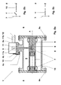
- Fig. 3 shows a first and Fig. 4 shows a second embodiment the invention.
- the earth switch device 1 '' comprises an encapsulation-side ground contact 50, 51; 500, an internal earthing contact 60; 600 and a terrestrial housing 3a, which serves to receive the earth drive 11 and that on an earth mounting side 3b of the gas-insulated Switchgear 13 with the GIS housing 2 of the gas-insulated Switchgear 13 is mechanically connected, wherein a electrically insulated measuring electrode 52, 520 for electrical Contacting the encapsulation-side ground contact 50, 51; 500 is present from the outside.
- the encapsulation-side ground contact 50, 51; 500, the measuring electrode 52, 520 and the earth housing 3a together on the same ground mounting side 3b are arranged and are the encapsulation-side ground contact 50, 51; 500 and the measuring electrode 52, 520 opposite to the Earth case 3a and the GIS housing 2 electrically isolated.
- the following example embodiments are given.
- the encapsulation-side ground contact 50, 51; 500 and the measuring electrode 52, 520 opposite the earth drive 11 and / or to any existing electrical connections 12 for the earth drive 11 and / or towards neighboring phases, especially opposite an optionally existing drive linkage 11b Neighbor phases, electrically isolated.
- the earth connection 53, 530 on the measuring flange 42 or the earth housing 3a mountable ground connection bracket 53, 530 in the mounted state, the measuring electrode 52, 520 with the measuring flange 42 or the earth housing 3a electrically short-circuits. Electrical measurements are therefore simplified because except the ground connection 53, 530 no other interrupted electrical contacts to the earth housing 3a Need to become. Due to the easy handling of the Personal protection improved during the measurements.
- An earth assembly 3 enclosed by the earth housing 3 a can via a combined support and measuring flange 40; 41, 42; 400 on the ground mounting side 3b with the GIS housing 2 mechanically be connected.
- the earthing housing is preferred 3a, the combined support and measuring flange 40; 41, 42; 400 and the GIS housing 2 electrically connected to each other.
- the earth housing 3 a is therefore always directly with the GIS housing 2 connected and requires no insulating Intermediate flange.
- the encapsulation-side ground contact is a movable earthing contact 50, 51 and includes an earthing contact pin 50, by a Isolierschaltstange 51 from Earth drive 11 electrically isolated and through the Isolierschaltstange 51 is drivable. Isolated is executed So only the pin 50 and not the entire earth electrode 1''. The internal earthing contact is then as earth contact 60 executed.
- the combined support and measuring flange 40; 41, 42 may, as shown, a along of the movable earthing contact 50, 51 extended support flange 41 and one laterally attached to the support flange 41 Measuring flange 42 for receiving and carrying the measuring electrode 52 have.
- the lateral access to the isolated executed contact pin 50 is connected to a ground connection 53 electrically conductive with the GIS housing 2 connected.
- This connection 53 is mounted in normal operation and creates contact between the ground contact pin 50 and GIS housing 2 and optionally earth housing 3a. For measurements where a measurement signal is applied to the earth contact system applied or tapped on this, only the earth connection 53 needs to be removed without that further work on the drive 11, its wiring 12 or his rod 11b are necessary.
- a dielectric insulation 44 for the electrical insulation of the measuring flange 42 of the measuring electrode 52 may be present.
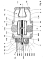
- Fig. 4 shows a second embodiment of the invention. This is exemplary using a combined isolator / earthing contactor 1 '' shown.
- the separation section 14 and the grounding path 15 are here by way of example in series arranged.
- the active parts 7 include next the conductors 7, a holder 7a, the optional formed as a power connection 7a along the transverse axis B. and a shield 7b for the movable contact tube 113 of the isolator / earthmover. Again, it's an earth-drive 11, a movable earth contact 600 and a Earth contact 500 available.
- the example here shown combined disconnector / earth drive includes besides the motor unit 11, a drive shaft 110, an insulating shaft 111 and a spindle 112 for driving the contact tube 113 and in particular the movable earthing contact 600th
- the encapsulation-side ground contact formed as a stationary contact 500, which by a dielectric Insulation 540 from the earth housing 3a electrically is isolated, and the internal ground contact is the movable earthing contact tube 600.
- the movable earthing contact 600 and the earth contact 500 are in the gas space. 9 the gas-insulated switchgear 13 is arranged.
- the earth contact 500 typically has a contact system 501, z. B. coil springs o. ⁇ ., On.
- the earth switching device 1 ' is particularly suitable for gas-insulated Medium or high voltage switchgear 13 suitable. claimed is also a switchgear 13 with such Earth switching device 1 '.
Landscapes
- Gas-Insulated Switchgears (AREA)
- Driving Mechanisms And Operating Circuits Of Arc-Extinguishing High-Tension Switches (AREA)
Abstract
Description
Die Erfindung bezieht sich auf das Gebiet der Hochspannungstechnik, insbesondere auf elektrische Isolations- und Anschlusstechnik für auf Erdpotential befindliche gasisolierte Schaltanlagen (GIS). Sie geht aus von einem Erderschaltgerät und einer gasisolierten Schaltanlage gemäss Oberbegriff der unabhängigen Patentansprüche.The invention relates to the field of high voltage engineering, in particular electrical insulation and Connection technology for gas-insulated at ground potential Switchgear (GIS). It starts from a grounding device and a gas-insulated switchgear according to Preamble of the independent claims.
Erderschaltgeräte in bestehenden gasisolierten Schaltanlagen können als sogenannte "isolierte Erder" ausgeführt werden. Bei diesen Varianten ist das Erdergehäuse von den restlichen Gehäusen der gasisolierten Schaltanlage (GIS) durch einen isolierenden Zwischenflansch abgetrennt. Im Normalbetrieb wird dieser isolierende Flansch durch eine massive Erdverbindung überbrückt. Für Messungen, bei denen ein Messsignal auf das Erderkontaktsystem aufgebracht oder über dieses abgegriffen wird, wird diese Überbrückung weggenommen.Earth-switching devices in existing gas-insulated switchgear can be implemented as so-called "isolated earth electrodes" become. In these variants, the earth housing of the remaining housings of the gas-insulated switchgear (GIS) separated by an insulating intermediate flange. in the Normal operation, this insulating flange is replaced by a massive earth connection bridged. For measurements in which a measuring signal applied to the earth contact system or this is taken over this bridging is taken away.
Ein solcher isolierter Erder ist in dem Artikel von M. Okabe et al., "Serialization of Standard Gas Insulated Switchgear", Hitachi Review Vol. 51 (2002), No. 5 offenbart. Die Erfindung nimmt auf diesen Stand der Technik Bezug. Dort ist ein herkömmlicher kombinierter Trenner/Erder-Schalter oder Dreistellungstrenner gezeigt, bei dem ein verschiebliches Kontaktteil durch Linearbewegung zwischen den Positionen "Trenner eingeschaltet", d. h. Trennerkontakt geschlossen, "Trenner ausgeschaltet", d. h. Trennerkontakt geöffnet und "Erder eingeschaltet", d. h. Erderkontakt zusätzlich geschlossen, bewegbar ist. Der Erderfestkontakt ist auf einem flachen Deckel der gasisolierten Schaltanlage (GIS) an der Deckelinnenseite montiert. Der Erderfestkontakt ist elektrisch vom GIS-Gehäuse isoliert aus diesem herausgeführt und kann aussen über einen Kontaktbügel mit dem GIS-Gehäuse kurzgeschlossen werden.Such an isolated earth electrode is in the article of Okabe et al., "Serialization of Standard Gas Insulated Switchgear ", Hitachi Review Vol. 51 (2002), No. 5. The invention takes this state of the art Reference. There is a conventional combined disconnector / earthing switch or Dreistellungstrenner shown in the a displaceable contact part by linear movement between the positions "isolator switched on", d. H. Disconnector contact closed, "Disconnector switched off", d. H. Disconnector contact opened and "earthing switched on", d. H. Earth contact additionally closed, movable. Of the Earthing contact is on a flat lid of the Gas-insulated switchgear (GIS) on the inside of the lid assembled. The earthing contact is electrically from the GIS housing isolated from this led out and can outside shorted to the GIS housing via a contact clip become.
Die EP 1 068 624 B1 offenbart ebenfalls einen kombinierten
Trenner/Erder-Schalter. Hierbei ist der Erderfestkontakt
als pinartiges Kontaktstück ausgebildet, das auf einem
Kontaktträger aufsitzt, der seinerseits an einem durch die
GIS-Gehäusewand nach aussen geführten, gegen die GIS-Gehäusewand
elektrisch isolierten Bolzen gehaltert ist.
Aufgabe der vorliegenden Erfindung ist es, einen verbesserten isolierten Erder für gasisolierte Schaltanlagen anzugeben. Diese Aufgabe wird erfindungsgemäss durch die Merkmale der unabhängigen Ansprüche gelöst.The object of the present invention is to provide an improved insulated earth electrode for gas-insulated switchgear specify. This object is achieved by the Features of the independent claims solved.
Die Erfindung besteht in einem Erderschaltgerät, insbesondere für gasisolierte gekapselte Hochspannungsschaltanlagen, umfassend einen kapselungsseitigen Erderkontakt, einen innenliegenden Erderkontakt und ein Erdergehäuse, das zur Aufnahme eines Erderantriebs dient und das an einer Erdermontageseite der gasisolierten Schaltanlage mit einem GIS-Gehäuse der gasisolierten Schaltanlage mechanisch verbunden ist, wobei eine elektrisch isolierte Messelektrode zur elektrischen Kontaktierung des kapselungsseitigen Erderkontakts von aussen vorhanden ist, wobei ferner der kapselungsseitige Erderkontakt, die Messelektrode und das Erdergehäuse gemeinsam an der Erdermontageseite angeordnet sind und der kapselungsseitige Erderkontakt und die Messelektrode gegenüber dem Erdergehäuse und dem GIS-Gehäuse elektrisch isoliert sind. Der Erder ist also vollständig, inklusive Antrieb und Messabgriff, auf nur einer Seite oder Montagefläche der GIS-Kapselung angeordnet und von dieser Seite her zugänglich. Das Erdergehäuse dient zur Aufnahme von Komponenten des Erderschaltgeräts und beherbergt typischerweise den Erderantrieb. Von den Erderkontakten ist mindestens einer ein beweglicher Erderkontakt. Durch die Erfindung wird eine sehr einfache Montierbarkeit und Zugänglichkeit des Erders und eine sehr einfache Anordnung und Bedienbarkeit der Messelektrode für elektrische Messungen an Aktivteilen von der gleichen Seite erreicht. Dadurch wird auch eine sehr kompakte Bauweise des Erders realisiert.The invention consists in a grounding device, in particular for gas-insulated, encapsulated high-voltage switchgear, comprising an encapsulation-side ground contact, an internal earthing contact and a grounding housing, which serves to receive an earth drive and that an earth mounting side of the gas-insulated switchgear with a GIS housing of the gas-insulated switchgear mechanically is connected, wherein an electrically insulated measuring electrode for electrical contacting of the encapsulation side Earth contact is present from the outside, where Furthermore, the encapsulation-side ground contact, the measuring electrode and the earth housing together on the earth mounting side are arranged and the encapsulation-side ground contact and the measuring electrode opposite the earth housing and the GIS housing are electrically isolated. The earth electrode is therefore complete, including drive and measuring tap, on only one side or mounting surface of the GIS encapsulation arranged and accessible from this side. The earth housing serves to accommodate components of the earthing switchgear and typically houses the earth drive. Of the earth contacts is at least one movable earthing contact. By the invention becomes a very easy mounting and accessibility of the earth and a very simple arrangement and operability of Measuring electrode for electrical measurements on active parts of reached the same page. This will also be a very realized compact design of the earth.
In einem ersten Ausführungsbeispiel ist die Messelektrode oder der Messabgriff durch das GIS-Gehäuse oder das Erdergehäuse elektrisch isoliert nach aussen durchgeführt und/oder durch eine von aussen montierbare Erdverbindung mit dem GIS-Gehäuse und/oder dem Erdergehäuse kurzschliessbar. Der Messabgriff ist also zur elektrischen Kontaktierung und Durchführung des kapselungsseitigen Erderkontakts durch das GIS-Gehäuse oder Erdergehäuse hindurch permanent installiert. Dies verursacht nur geringe Mehrkosten. Dadurch entfällt ein spezieller, teurer Isolierflansch mit aufwendig beidseitig eingegossenen Bolzen, der früher gegebenenfalls zwischen GIS-Gehäuse und Erdergehäuse für Messzwecke montiert werden musste. Die zuvor unterschiedlichen Bautypen des isolierten und nicht isolierten Erders sind jetzt baugleich ausführbar. Wenn alle Erder isoliert ausgeführt sind, können Messungen auch an unterschiedlichen Stellen in der GIS-Anlage und daher mit besserer Aussagekraft durchgeführt werden.In a first embodiment, the measuring electrode or the measuring tap through the GIS housing or the earth housing electrically isolated to the outside and / or by an externally mountable earth connection can be short-circuited with the GIS housing and / or the grounding housing. The measuring tap is therefore for electrical Contacting and execution of the encapsulation side Earth contact through the GIS housing or earthing housing permanently installed. This causes only minor Additional costs. This eliminates a special, expensive Isolierflansch with intricately cast-in bolts on both sides, the former possibly between GIS housing and earth housing had to be mounted for measurement purposes. The before different building types of isolated and non-isolated Erders are now structurally executable. If all Erder isolated, measurements can also be made different places in the GIS plant and therefore with better meaningfulness.
In einem weiteren Ausführungsbeispiel ist der kapselungsseitige Erderkontakt und die Messelektrode gegenüber dem Erderantrieb und/oder gegenüber gegebenenfalls vorhandenen elektrischen Anschlüssen für den Erderantrieb und/oder gegenüber Nachbarphasen, insbesondere gegenüber einem gegebenenfalls vorhandenen Antriebsgestänge zu Nachbarphasen, elektrisch isoliert. Dies vereinfacht die Durchführung elektrischer Messungen, da nur noch die Erdverbindung entfernt werden muss, jedoch keine anderen Elemente, wie z. B. Antriebskabel oder Antriebsgestänge zu Nachbarphasen in dreiphasig oder einphasig gekapselten Schaltanlagen.In another embodiment, the encapsulation side Earth contact and the measuring electrode opposite the Earth drive and / or compared to any existing electrical connections for the earth drive and / or to neighboring phases, in particular to one if necessary existing drive linkage to neighboring phases, electrically isolated. This simplifies the implementation electrical measurements, since only the ground connection removed but no other elements, like z. B. drive cable or drive linkage to neighboring phases in three-phase or single-phase encapsulated switchgear.
Das Ausführungsbeispiel gemäss Anspruch 4 hat den Vorteil, dass es für die Zwecke der Erfindung keine Rolle spielt, ob der kapselungsseitige Erderkontakt ein beweglicher Erderkontakt oder ein Festkontakt ist. Somit ist die Erfindung für beliebige Erdertypen anwendbar unabhängig davon, ob der bewegliche Erderkontakt von innen nach aussen, d. h. zur Kapselungswand hin, oder von aussen nach innen bewegbar ist.The embodiment according to claim 4 has the advantage that it does not matter for the purposes of the invention, whether the encapsulation-side ground contact a movable Earth contact or a fixed contact. Thus, the Invention applicable to any type of earth independently of whether the mobile earth contact from the inside to the outside, d. H. towards the enclosure wall, or from outside is movable inside.
Das Ausführungsbeispiel gemäss Anspruch 5 hat den Vorteil,
dass der Erder als ganzes an einem einzigen Flansch hängt,
der zugleich das Erdergehäuse trägt (Tragflansch) und einen
separaten Zugang für die Messelektrode aufweist (Messflansch).
Diese Anordnung ist besonders platzsparend.The embodiment according to
Die Ansprüche 6-7 betreffen Ausführungsbeispiele für einen Erder und insbesondere Schnellerder, bei dem der Tragflansch und der Messflansch orthogonal zueinander angeordnet sind.The claims 6-7 relate to embodiments of a Earth electrode and in particular Schnellerder, in which the flange and the measuring flange orthogonal to each other are.
Anspruch 10 betrifft eine elektrische Schaltanlage umfassend
ein Erdschaltgerät wie zuvor beschrieben und mit den
dort genannten Vorteilen.
Weitere Ausführungen, Vorteile und Anwendungen der Erfindung ergeben sich aus den abhängigen Ansprüchen sowie aus der nun folgenden Beschreibung und den Figuren.Further embodiments, advantages and applications of the invention result from the dependent claims as well as from the following description and the figures.
- Fig. 1a, 1bFig. 1a, 1b
- zeigen schematisch im Querschnitt ein nicht isoliertes Erderschaltgerät gemäss Stand der Technik (Fig. 1a) mit zugehörigem Schaltbild (Fig. 1b);do not show schematically in cross section insulated earth switching device according to the state of Technology (Fig. 1a) with associated circuit diagram (Fig. 1b);
- Fig. 2a-2cFig. 2a-2c
- zeigen schematisch im Querschnitt ein isoliertes Erderschaltgerät gemäss Stand der Technik (Fig. 2a) mit zugehörigem Schaltbild (Fig. 2b, 2c); show schematically in cross section an isolated Earth switching device according to the state of Technique (Fig. 2a) with associated circuit diagram (Figures 2b, 2c);
- Fig. 3Fig. 3
- zeigt schematisch im Querschnitt ein Ausführungsbeispiel eines separaten Erderschaltgeräts mit erfindungsgemäss isoliertem Erderschaltstift; undshows schematically in cross section an embodiment a separate earthing device with inventively insulated earthing switch pin; and
- Fig. 4Fig. 4
- zeigt schematisch im Querschnitt ein Ausführungsbeispiel eines kombinierten Trenner/Erders mit erfindungsgemäss isoliertem Erderfestkontakt.shows schematically in cross section an embodiment of a combined separator / earth electrode with earth-electrode contact insulated according to the invention.
In den Figuren sind gleiche Teile mit gleichen Bezugszeichen versehen.In the figures, the same parts are given the same reference numerals Mistake.
Fig. 1a zeigt ein herkömmliches nichtisoliertes Erderschaltgerät
1 in einer gekapselten gasisolierten Schaltanlage
13. Das Gehäuse 2 der gasisolierten Schaltanlage 13
umschliesst einen Gasraum 9, der bevorzugt mit SF6-Gas
unter einigen bar Druck gefüllt ist. Der Erderanbau 3 mit
seinem Erdergehäuse 3a ist am GIS-Gehäuse 2 über einen
Montageflansch 4a befestigt. Ein beweglicher Erderkontaktstift
5 wird vom typischerweise im Erdergehäuse 3a
angeordneten Erderantrieb 11 entlang einer Antriebsbewegung
11a zum Erderfestkontakt 6 hinbewegt, um Aktivteile
7 der gekapselten gasisolierten Schaltanlage 13 zu erden.
Im Normalbetrieb der Schaltanlage 13 ist der Stift 5 zurückgezogen
und die Aktivteile 7 stehen unter Hochspannung
und/oder tragen Betriebsstrom oder Kurzschlussstrom. Die
Aktivteile oder Stromleiter 7 sind von Isolatoren 8, insbesondere
Stützisolatoren 8 und Schottisolatoren 8, im
gasgefüllten Innenraum 9 der Kapselung 2 gehalten. Die
Isolatoren 8 sind ihrerseits mittels Isolatorflanschen 8a
an der GIS-Kapselung 2 abgestützt. Die Längsachse des
nicht isolierten Schnellerders 1 ist mit A bezeichnet.Fig. 1a shows a conventional non-insulated
Fig. 1b zeigt das Schaltschema des nicht isolierten
Schaltgeräts 1, wonach das Erdpotential durch das GIS-Gehäuse
2 definiert ist und das gesamte Gerät 1 mitsamt
dem Erdergehäuse 3a und den Erderkontakten 5, 6 im Erdungsfall
mit Erdungspotential elektrisch verbunden ist.
Das Erdergehäuse 3a oder der Erderanbau 3 sind zusätzlich
über Antriebsleitungen 12 und/oder Antriebsgestänge 11b
mit der Aussenwelt elektrisch verbunden.Fig. 1b shows the circuit diagram of the
Fig. 2a zeigt den Erder oder Schnellerder 1' wie zuvor,
jedoch in einer isolierten Ausführungsform. Hierfür ist
der Erderanbau 3 mit dem Erdergehäuse 3a durch einen isolierenden
Zwischenflansch 4b vom GIS-Gehäuse 2 elektrisch
isoliert. Im Normalbetrieb ist der Zwischenflansch 4b
durch einen Erdungsbügel 10 überbrückt, der das Erdergehäuse
3a mit dem GIS-Gehäuse 2 kurzschliesst. Sollen
elektrische Messungen durchgeführt werden, so wird der Bügel
10 abgenommen und das Erdergehäuse 3a dient als eine
Messelektrode. Deshalb müssen auch andere elektrische Verbindungen
zum Erdergehäuse 3a, insbesondere elektrische
Anschlüsse 12 und Antriebsgestänge 11b, entfernt werden.
Dies ist umständlich und arbeitsintensiv.FIG. 2a shows the earth electrode or fast line 1 'as before,
however, in an isolated embodiment. For this is
the
Fig. 2b bzw. Fig. 2c zeigen das Schaltschema des isolierten
Erderschaltgeräts 1' im Normalbetrieb bzw. bei elektrischen
Messungen an Aktivteilen 7 der Schaltanlage 13 im
geerdeten Zustand. Bei abgenommenem Bügel 10 ist also die
Erdung aufgehoben und die Messungen können durchgeführt
werden.Fig. 2b and Fig. 2c show the circuit diagram of the isolated
Earth switching device 1 'in normal operation or in electrical
Measurements of
Bei den meisten heutigen Realisierungen von Erderschaltgeräten
1, 1' wird der bewegte Kontakt 5 von aussen, d. h.
von der Kapselung 2 her, nach innen zu den Aktivteilen 7
hin bewegt. Der Erderfestkontakt 6 ist typischerweise in
die Aktivteile 7 im Innenrohr integriert. Bekannte Erderschaltgeräte
1 oder 1' werden an geeigneten Flanschen 4a
in den Schaltanlagen 13 montiert. Diese Flansche 4a sind
entweder Standardflansche, welche bei jeder Verbindung benützt
werden oder kleinere Flansche, welche speziell für
den Anbau der Erderschaltgeräte 1, 1' ausgelegt sind.For most modern day
Fig. 3 zeigt ein erstes und Fig. 4 ein zweites Ausführungsbeispiel
der Erfindung. Das Erderschaltgerät 1'' umfasst
einen kapselungsseitigen Erderkontakt 50, 51; 500,
einen innenliegenden Erderkontakt 60; 600 und ein Erdergehäuse
3a, das zur Aufnahme des Erderantriebs 11 dient
und das an einer Erdermontageseite 3b der gasisolierten
Schaltanlage 13 mit dem GIS-Gehäuse 2 der gasisolierten
Schaltanlage 13 mechanisch verbunden ist, wobei eine
elektrisch isolierte Messelektrode 52, 520 zur elektrischen
Kontaktierung des kapselungsseitigen Erderkontakts
50, 51; 500 von aussen vorhanden ist. Gemäss der Erfindung
sind im Erderschaltgerät 1'' der kapselungsseitige Erderkontakt
50, 51; 500, die Messelektrode 52, 520 und das Erdergehäuse
3a gemeinsam an der gleichen Erdermontageseite
3b angeordnet und sind der kapselungsseitige Erderkontakt
50, 51; 500 und die Messelektrode 52, 520 gegenüber dem
Erdergehäuse 3a und dem GIS-Gehäuse 2 elektrisch isoliert.
Im folgenden werden hierzu Ausführungsbeispiele angegeben.Fig. 3 shows a first and Fig. 4 shows a second embodiment
the invention. The earth switch device 1 '' comprises
an encapsulation-
Mit Vorteil sind der kapselungsseitige Erderkontakt 50,
51; 500 und die Messelektrode 52, 520 gegenüber dem Erderantrieb
11 und/oder gegenüber gegebenenfalls vorhandenen
elektrischen Anschlüssen 12 für den Erderantrieb 11
und/oder gegenüber Nachbarphasen, insbesondere gegenüber
einem gegebenenfalls vorhandenen Antriebsgestänge 11b zu
Nachbarphasen, elektrisch isoliert. Bevorzugt ist die Erdverbindung
53, 530 ein auf den Messflansch 42 oder das Erdergehäuse
3a aufmontierbarer Erdverbindungsbügel 53, 530,
der im aufmontierten Zustand die Messelektrode 52, 520 mit
dem Messflansch 42 oder dem Erdergehäuse 3a elektrisch
kurzschliesst. Elektrische Messungen sind also vereinfacht,
weil ausser der Erdverbindung 53, 530 keine anderen
elektrischen Kontakte zum Erdergehäuse 3a unterbrochen
werden müssen. Durch die einfache Handhabung wird der
Personenschutz bei den Messungen verbessert.Advantageously, the encapsulation-
Ein vom Erdergehäuse 3a umschlossener Erderanbau 3 kann
über einen kombinierten Trag- und Messflansch 40; 41, 42;
400 an der Erdermontageseite 3b mit dem GIS-Gehäuse 2 mechanisch
verbunden sein. Bevorzugt sind das Erdergehäuse
3a, der kombinierte Trag- und Messflansch 40; 41, 42; 400
und das GIS-Gehäuse 2 miteinander elektrisch leitend verbunden.
Das Erdergehäuse 3a ist also immer direkt mit dem
GIS-Gehäuse 2 verbunden und benötigt keinen isolierenden
Zwischenflansch.An
Gemäss Fig. 3 ist der kapselungsseitige Erderkontakt ein
beweglicher Erderkontakt 50, 51 und umfasst einen Erderkontaktstift
50, der durch eine Isolierschaltstange 51 vom
Erderantrieb 11 elektrisch isoliert und durch die Isolierschaltstange
51 antreibbar ist. Isoliert ausgeführt ist
also nur der Kontaktstift 50 und nicht der gesamte Erder
1''. Der innenliegende Erderkontakt ist dann als Erderfestkontakt
60 ausgeführt. Der kombinierte Trag- und Messflansch
40; 41, 42 kann, wie dargestellt, einen entlang
des beweglichen Erderkontakts 50, 51 erstreckten Tragflansch
41 und einen am Tragflansch 41 seitlich angebauten
Messflansch 42 zur Aufnahme und Durchführung der Messelektrode
52 aufweisen. Der seitliche Zugriff auf den
isoliert ausgeführten Kontaktstift 50 ist mit einer Erdverbindung
53 mit dem GIS-Gehäuse 2 elektrisch leitend
verbunden. Diese Verbindung 53 ist im Normalbetrieb angebracht
und schafft den Kontakt zwischen Erderkontaktstift
50 und GIS-Gehäuse 2 sowie gegebenenfalls Erdergehäuse 3a.
Für Messungen, bei denen ein Messsignal auf das Erderkontaktsystem
aufgebracht oder über dieses abgegriffen wird,
braucht nur die Erdverbindung 53 entfernt zu werden, ohne
dass weitere Arbeiten am Antrieb 11, seiner Verkabelung 12
oder seinem Gestänge 11b nötig sind.According to FIG. 3, the encapsulation-side ground contact is a
Im Inneren des Tragflansches 41 kann eine dielektrische
Isolation 43 zur elektrischen Isolierung des Tragflansches
41 vom beweglichen Erderkontakt 50, 51, insbesondere vom
Erderkontaktstift 50, angeordnet sein. Zudem kann auch im
Inneren des Messflansches 42 eine dielektrische Isolation
44 zur elektrischen Isolierung des Messflansches 42 von
der Messelektrode 52 vorhanden sein.Inside the
Fig. 4 zeigt eine zweite Ausführungsform der Erfindung.
Diese ist beispielhaft anhand eines kombinierten Trenner/Erder-Schaltgeräts
1'' gezeigt. Die Trennstrecke 14 und
die Erdungsstrecke 15 sind hier beispielhaft in Serie hintereinander
angeordnet. Die Aktivteile 7 umfassen neben
den Stromleitern 7 auch eine Halterung 7a, die optional
als Stromverbindung 7a entlang der Querachse B ausgebildet
sein kann, und eine Abschirmung 7b für das bewegliche Kontaktrohr
113 des Trenner/Erders. Wiederum sind ein Erderantrieb
11, ein beweglicher Erderkontakt 600 und ein
Erderfestkontakt 500 vorhanden. Der hier beispielhaft
gezeigte kombinierte Trenner/Erder-Antrieb umfasst neben
der Motoreinheit 11 eine Antriebswelle 110, eine Isolierwelle
111 und eine Spindel 112 zum Antrieb des Kontaktrohrs
113 und insbesondere des beweglichen Erderkontakts
600.Fig. 4 shows a second embodiment of the invention.
This is exemplary using a combined isolator / earthing contactor
1 '' shown. The
Gemäss Fig. 4 ist also der kapselungsseitige Erderkontakt
als Erderfestkontakt 500 ausgebildet, der durch eine dielektrische
Isolation 540 vom Erdergehäuse 3a elektrisch
isoliert ist, und der innenliegende Erderkontakt ist das
bewegliche Erderkontaktrohr 600. Der bewegliche Erderkontakt
600 und der Erderfestkontakt 500 sind im Gasraum 9
der gasisolierten Schaltanlage 13 angeordnet. Der Erderfestkontakt
500 weist typischerweise ein Kontaktsystem
501, z. B. Spiralfedern o. ä., auf.According to FIG. 4, therefore, the encapsulation-side ground contact
formed as a
Durch die Montage des Erderschaltgeräts 1'', inklusive
Erdergehäuse 3a, Antrieb 11 und isoliertem Messabgriff 52,
520, an einer einzigen Erdermontageseite 3b, nämlich an
einer radialen Position (Fig. 3) oder endseitig axialen
Position (Fig. 4) am GIS-Gehäuse 2, wird eine sehr kompakte
Bauweise und zugleich einfache Bedienbarkeit des Messabgriffs
53, 530 erreicht. Dies gilt für einphasig oder
dreiphasig gekapselte Schaltanlagen 13.By mounting the earth switch 1 ',
Das Erderschaltgerät 1' ist besonders für gasisolierte
Mittel- oder Hochspannungsschaltanlagen 13 geeignet. Beansprucht
wird auch eine Schaltanlage 13 mit einem solchen
Erderschaltgerät 1'. The earth switching device 1 'is particularly suitable for gas-insulated
Medium or
- 11
- Herkömmlicher nicht isolierter ErderConventional non-insulated earth electrode
- 1'1'
- Herkömmlicher isolierter ErderConventional isolated earth electrode
- 1''1''
- erfindungsgemässer isolierter ErderInsulated earth electrode according to the invention
- 22
- GIS-GehäuseGIS housing
- 33
- Erderanbau mit ErderantriebEarthmoving with earth drive
- 3a3a
- Erdergehäuseearthing switch housing
- 3b3b
- Erdermontageseiteearthing switch mounting side
- 4a4a
- Flansch für Erderanbau, Montageflansch, Tragflansch (Stand der Technik)Flange for earth mounting, mounting flange, flange (State of the art)
- 4b4b
- Zwischenflansch für Erderanbau, Isolierflansch (Stand der Technik)Intermediate flange for earth mounting, insulating flange (State of the art)
- 40, 40040, 400
- kombinierter Trag- und Messflansch für Erderanbau, Erderflansch mit Messabgriffcombined support and measuring flange for soil cultivation, Earth flange with measuring tap
- 4141
- verlängerter Tragflanschextended support flange
- 4242
- Messflansch, Messdurchführung für ErderkontaktstiftMeasuring flange, measuring bushing for earthing contact pin
- 4343
- Isolation zwischen Tragflansch und KontaktstiftInsulation between support flange and contact pin
- 4444
- Isolation zwischen Messflansch und MesselektrodeIsolation between measuring flange and measuring electrode
- 55
- Beweglicher ErderkontaktstiftMovable earthing contact pin
- 5050
- gehäuseseitiger Erderkontakt, beweglicher isolierter Erderkontaktstifthousing-side earth contact, movable insulated earthing switch contact pin
- 5151
- Isolierschaltstange für ErderkontaktstiftIsolierschaltstange for earthing contact pin
- 5252
- Messelektrode, seitlicher Messabgriff an ErderkontaktstiftMeasuring electrode, lateral measuring tap on earth contact pin
- 5353
- Erdverbindung für Messelektrode, abnehmbarer Kontaktstift-ErdungsbügelEarth connection for measuring electrode, removable Pin grounding strap
- 500500
- gehäuseseitiger Erderkontakt, im Montagedeckel integrierter ErderfestkontaktHousing-side earthing contact, in the mounting cover integrated earthing contact
- 501501
- KontaktsystemContact system
- 520520
- Messelektrode, axialer Messabgriff an ErderfestkontaktMeasuring electrode, axial measuring tap on earthing contact
- 530530
- Erdverbindung für Messelektrode, abnehmbarer Festkontakt-ErdungsbügelEarth connection for measuring electrode, removable Solid-contact grounding strap
- 540540
- Isolation zwischen Erdergehäuse und ErderfestkontaktInsulation between earthing housing and earthing contact
- 66
- Erderfestkontaktearthing switch fixed
- 6060
- innenliegender Erderkontakt, Erderfestkontakt internal earthing contact, earthing contact
- 600600
- innenliegender Erderkontakt, bewegliches Erderkontaktrohrinternal earthing contact, movable earthing contact tube
- 77
- Aktivteile der Schaltanlage, Stromleiter (auf Hochspannungspotential)Active parts of the switchgear, power conductors (auf High-voltage potential)
- 7a7a
- Halterung, optionale StromverbindungBracket, optional power connection
- 7b7b
- Abschirmung für bewegliches KontaktrohrShielding for movable contact tube
- 88th
- Isolator, Stützisolator, SchottisolatorIsolator, post insulator, isolator
- 8a8a
- Isolatorflanschinsulator flange
- 99
- Gasraum, SF6 Gas room, SF 6
- 1010
- Erdverbindung, ErdungsbügelGround connection, grounding strap
- 1111
- Erderantriebearthing switch drive
- 11a11a
- Antriebsbewegungdrive movement
- 11b11b
- Antriebsgestänge zu NachbarphasenDrive linkage to neighboring phases
- 110110
- Antriebswelledrive shaft
- 111111
- Isolierwelleinsulating shaft
- 112112
- Spindelspindle
- 113113
- Kontaktrohrcontact tube
- 1212
- Elektrische AnschlüsseElectrical connections
- 1313
- Gasisolierte Schaltanlage (GIS)Gas-insulated switchgear (GIS)
- 1414
- Trennstreckeisolating distance
- 1515
- Erdungsstreckeground distance
- AA
- Achse des Schaltanlagenabschnitts, LängsachseAxle of the switchgear section, longitudinal axis
- BB
- Querachsetransverse axis
Claims (10)
Priority Applications (7)
| Application Number | Priority Date | Filing Date | Title |
|---|---|---|---|
| EP04405117A EP1569256B1 (en) | 2004-02-27 | 2004-02-27 | Insulated earthing switch for GIS |
| DE502004001261T DE502004001261D1 (en) | 2004-02-27 | 2004-02-27 | Insulated earth switching device for gas-insulated switchgear |
| AT04405117T ATE337609T1 (en) | 2004-02-27 | 2004-02-27 | INSULATED EARTH SWITCHGEAR FOR GAS-INSULATED SWITCHGEAR |
| JP2005043507A JP4472552B2 (en) | 2004-02-27 | 2005-02-21 | Insulated Earthing Switch for Gas Insulated Switchgear Device |
| CN200510051682XA CN1661872B (en) | 2004-02-27 | 2005-02-25 | Insulated earthing switch for gas-insulated switchgear assemblies |
| US11/066,150 US7122758B2 (en) | 2004-02-27 | 2005-02-25 | Insulated earthing switch for gas-insulated switchgear assemblies |
| KR1020050015980A KR101123223B1 (en) | 2004-02-27 | 2005-02-25 | Insulated earthing switch for gas-insulated switchgear assemblies |
Applications Claiming Priority (1)
| Application Number | Priority Date | Filing Date | Title |
|---|---|---|---|
| EP04405117A EP1569256B1 (en) | 2004-02-27 | 2004-02-27 | Insulated earthing switch for GIS |
Publications (2)
| Publication Number | Publication Date |
|---|---|
| EP1569256A1 true EP1569256A1 (en) | 2005-08-31 |
| EP1569256B1 EP1569256B1 (en) | 2006-08-23 |
Family
ID=34746198
Family Applications (1)
| Application Number | Title | Priority Date | Filing Date |
|---|---|---|---|
| EP04405117A Expired - Lifetime EP1569256B1 (en) | 2004-02-27 | 2004-02-27 | Insulated earthing switch for GIS |
Country Status (7)
| Country | Link |
|---|---|
| US (1) | US7122758B2 (en) |
| EP (1) | EP1569256B1 (en) |
| JP (1) | JP4472552B2 (en) |
| KR (1) | KR101123223B1 (en) |
| CN (1) | CN1661872B (en) |
| AT (1) | ATE337609T1 (en) |
| DE (1) | DE502004001261D1 (en) |
Cited By (3)
| Publication number | Priority date | Publication date | Assignee | Title |
|---|---|---|---|---|
| EP2026431A2 (en) * | 2006-11-29 | 2009-02-18 | AREVA Energietechnik GmbH | Switch module for an electrical switch device |
| EP3076420A1 (en) * | 2015-03-31 | 2016-10-05 | General Electric Technology GmbH | Quick earth connection with breaking capacity for a station under a metal shell |
| EP4287232A1 (en) * | 2022-06-02 | 2023-12-06 | General Electric Company | Insulated earthing switch for an air insulated or mixed switchgear |
Families Citing this family (14)
| Publication number | Priority date | Publication date | Assignee | Title |
|---|---|---|---|---|
| WO2010111808A1 (en) * | 2009-04-03 | 2010-10-07 | Abb Technology Ltd. | Bushing for connecting gas insulated switchgear with air insulated switchgear |
| CN102072703B (en) * | 2010-11-04 | 2012-10-03 | 中国电力科学研究院 | Optical measurement device and method for separation of GIS (Gas Insulated Switchgear) |
| JP6042344B2 (en) * | 2010-12-14 | 2016-12-14 | アーベーベー・テヒノロギー・アーゲー | Dielectric insulation medium |
| US9325104B2 (en) | 2013-05-24 | 2016-04-26 | Thomas & Betts International, Inc. | Gelatinous dielectric material for high voltage connector |
| US9437374B2 (en) | 2013-05-24 | 2016-09-06 | Thomas & Betts International Llc | Automated grounding device with visual indication |
| KR102018872B1 (en) * | 2013-06-24 | 2019-09-06 | 현대일렉트릭앤에너지시스템(주) | Earth switch driving mechanism of load break switch |
| US9443681B2 (en) | 2013-07-29 | 2016-09-13 | Thomas & Betts International Llc | Flexible dielectric material for high voltage switch |
| CN104836188A (en) * | 2015-04-15 | 2015-08-12 | 江苏华江科技有限公司 | Cable connecting housing for ultrahigh-voltage GIS breaker switch |
| CN104835676A (en) * | 2015-04-15 | 2015-08-12 | 江苏华江科技有限公司 | Ultrahigh-voltage GIS isolating switch housing |
| CN108695081B (en) * | 2017-04-06 | 2022-07-12 | 伊顿电力设备有限公司 | Three-station opening and closing operation device and three-station opening and closing device |
| DE102019212109A1 (en) * | 2019-08-13 | 2021-02-18 | Siemens Aktiengesellschaft | Electrical switchgear |
| CN113035627B (en) * | 2021-03-29 | 2023-12-29 | 山东泰开电力开关有限公司 | Single-body split-box type linear three-position switch structure and use method thereof |
| US11862944B1 (en) | 2022-06-17 | 2024-01-02 | Jst Power Equipment, Inc. | Switchgear device with grounding device and related methods |
| US12476055B2 (en) * | 2023-03-17 | 2025-11-18 | Hyundai Electric & Energy Systems Co., Ltd. | Earthing switch |
Citations (1)
| Publication number | Priority date | Publication date | Assignee | Title |
|---|---|---|---|---|
| WO1999052119A1 (en) * | 1998-04-03 | 1999-10-14 | Siemens Aktiengesellschaft | Encapsulating module with a three-position switch integrated into a current path for a gas-insulated switchgear installation |
Family Cites Families (6)
| Publication number | Priority date | Publication date | Assignee | Title |
|---|---|---|---|---|
| DE1615835A1 (en) * | 1967-04-06 | 1971-09-09 | Bbc Brown Boveri & Cie | Separator for fully insulated electrical high-voltage switchgear |
| US3876846A (en) * | 1972-08-16 | 1975-04-08 | Ite Imperial Corp | Combination ground and test switch apparatus for pressurized-gas-insulated high voltage systems |
| JPS61141733U (en) * | 1985-02-22 | 1986-09-02 | ||
| FR2609837B1 (en) * | 1987-01-19 | 1989-04-14 | Merlin Gerin | SELF-EXPANSION POLYPHASE CIRCUIT BREAKER WITH POLE-SHIELDED CUT-OFF CHAMBER |
| DE19825386C2 (en) * | 1998-05-28 | 2000-05-11 | Siemens Ag | Encapsulation module with a combined isolating-earthing switch for a gas-insulated switchgear |
| AU763276B2 (en) * | 2001-02-07 | 2003-07-17 | Hitachi Limited | Gas insulated switchgear |
-
2004
- 2004-02-27 DE DE502004001261T patent/DE502004001261D1/en not_active Expired - Lifetime
- 2004-02-27 EP EP04405117A patent/EP1569256B1/en not_active Expired - Lifetime
- 2004-02-27 AT AT04405117T patent/ATE337609T1/en active
-
2005
- 2005-02-21 JP JP2005043507A patent/JP4472552B2/en not_active Expired - Fee Related
- 2005-02-25 CN CN200510051682XA patent/CN1661872B/en not_active Expired - Lifetime
- 2005-02-25 US US11/066,150 patent/US7122758B2/en not_active Expired - Fee Related
- 2005-02-25 KR KR1020050015980A patent/KR101123223B1/en not_active Expired - Lifetime
Patent Citations (1)
| Publication number | Priority date | Publication date | Assignee | Title |
|---|---|---|---|---|
| WO1999052119A1 (en) * | 1998-04-03 | 1999-10-14 | Siemens Aktiengesellschaft | Encapsulating module with a three-position switch integrated into a current path for a gas-insulated switchgear installation |
Cited By (4)
| Publication number | Priority date | Publication date | Assignee | Title |
|---|---|---|---|---|
| EP2026431A2 (en) * | 2006-11-29 | 2009-02-18 | AREVA Energietechnik GmbH | Switch module for an electrical switch device |
| EP3076420A1 (en) * | 2015-03-31 | 2016-10-05 | General Electric Technology GmbH | Quick earth connection with breaking capacity for a station under a metal shell |
| EP4287232A1 (en) * | 2022-06-02 | 2023-12-06 | General Electric Company | Insulated earthing switch for an air insulated or mixed switchgear |
| US12413053B2 (en) | 2022-06-02 | 2025-09-09 | Ge Vernova Infrastructure Technology Llc | Insulated earthing switch for an air insulated or mixed switchgear |
Also Published As
| Publication number | Publication date |
|---|---|
| JP4472552B2 (en) | 2010-06-02 |
| KR20060042376A (en) | 2006-05-12 |
| US7122758B2 (en) | 2006-10-17 |
| CN1661872B (en) | 2011-10-05 |
| EP1569256B1 (en) | 2006-08-23 |
| ATE337609T1 (en) | 2006-09-15 |
| CN1661872A (en) | 2005-08-31 |
| KR101123223B1 (en) | 2012-03-20 |
| DE502004001261D1 (en) | 2006-10-05 |
| JP2005245196A (en) | 2005-09-08 |
| US20050189325A1 (en) | 2005-09-01 |
Similar Documents
| Publication | Publication Date | Title |
|---|---|---|
| EP1569256B1 (en) | Insulated earthing switch for GIS | |
| EP0291762B1 (en) | Metal-clad, gas filled, multiphase high voltage switchgear | |
| EP0735637B1 (en) | Switchgear having a grounded metal casing filled with insulating gas | |
| EP0688071B2 (en) | Metal-clad gas-insulated switchgear | |
| EP1569255B1 (en) | Compact earthing switch for gas insulated substation | |
| EP0678954B1 (en) | Metal-clad gas-insulated switch installation | |
| EP0678955B1 (en) | Metal-clad gas-insulated switch installation | |
| EP0152611B1 (en) | Metal-enclosed gas-insulated switch installation | |
| EP1249910A2 (en) | High voltage switch for a gas insulated switching installation | |
| WO2005074074A2 (en) | Compressed gas insulated separating switch component and leadthrough arrangement | |
| EP1629580B1 (en) | Switch assembly | |
| EP1629581B1 (en) | Disconnecting switch assembly | |
| WO2007051319A1 (en) | High-voltage circuit breaker and breaker arrangement | |
| DE29823222U1 (en) | Gas-insulated, three-phase encapsulated switchgear | |
| DE4216970A1 (en) | High-tension air-break isolating switch with rotary contact arm - incorporates vertical arrangement of upper and lower insulator strings joined by gearbox for arm rotation in vertical plane | |
| DE102006001237A1 (en) | Three-phase insulated high voltage switch gear, has supporting unit with insulating connector provided between circuit breaker and bus bar region, where connector is formed such that circuit breaker is stabilized in its position | |
| DE102006040036A1 (en) | Arrangement with an electrical switching device | |
| DE102007033705B4 (en) | Converter arrangement of a metal-enclosed, gas-insulated switchgear and metal-enclosed, gas-insulated switchgear | |
| DE102010004971A1 (en) | Current transformer module for high or medium voltage switchgear, has cabinet with common gas space for receiving isolation gas of nominal guards and single phase region for locating current transformers | |
| DE19649613A1 (en) | Circuit-breaker module for gas-insulated high voltage (HV) switchgear | |
| EP1513236A2 (en) | Gas insulated cable connector | |
| WO2004109877A2 (en) | Switchgear comprising disconnecting switches integrated into an outdoor bushing | |
| DE3640945A1 (en) | ENCLOSED CONTROL PANEL | |
| DE102006031219A1 (en) | Circuit breaker with a housing |
Legal Events
| Date | Code | Title | Description |
|---|---|---|---|
| PUAI | Public reference made under article 153(3) epc to a published international application that has entered the european phase |
Free format text: ORIGINAL CODE: 0009012 |
|
| AK | Designated contracting states |
Kind code of ref document: A1 Designated state(s): AT BE BG CH CY CZ DE DK EE ES FI FR GB GR HU IE IT LI LU MC NL PT RO SE SI SK TR |
|
| AX | Request for extension of the european patent |
Extension state: AL LT LV MK |
|
| 17P | Request for examination filed |
Effective date: 20060113 |
|
| GRAP | Despatch of communication of intention to grant a patent |
Free format text: ORIGINAL CODE: EPIDOSNIGR1 |
|
| AKX | Designation fees paid |
Designated state(s): AT BE BG CH CY CZ DE DK EE ES FI FR GB GR HU IE IT LI LU MC NL PT RO SE SI SK TR |
|
| RIN1 | Information on inventor provided before grant (corrected) |
Inventor name: HOLAUS, WALTER Inventor name: MANZ, ERWIN Inventor name: SOLOGUREN-SANCHEZ, DIEGO Inventor name: SCHWEIZER, CHRISTOPH |
|
| GRAS | Grant fee paid |
Free format text: ORIGINAL CODE: EPIDOSNIGR3 |
|
| GRAA | (expected) grant |
Free format text: ORIGINAL CODE: 0009210 |
|
| AK | Designated contracting states |
Kind code of ref document: B1 Designated state(s): AT BE BG CH CY CZ DE DK EE ES FI FR GB GR HU IE IT LI LU MC NL PT RO SE SI SK TR |
|
| PG25 | Lapsed in a contracting state [announced via postgrant information from national office to epo] |
Ref country code: CZ Free format text: LAPSE BECAUSE OF FAILURE TO SUBMIT A TRANSLATION OF THE DESCRIPTION OR TO PAY THE FEE WITHIN THE PRESCRIBED TIME-LIMIT Effective date: 20060823 Ref country code: IT Free format text: LAPSE BECAUSE OF FAILURE TO SUBMIT A TRANSLATION OF THE DESCRIPTION OR TO PAY THE FEE WITHIN THE PRESCRIBED TIME-LIMIT;WARNING: LAPSES OF ITALIAN PATENTS WITH EFFECTIVE DATE BEFORE 2007 MAY HAVE OCCURRED AT ANY TIME BEFORE 2007. THE CORRECT EFFECTIVE DATE MAY BE DIFFERENT FROM THE ONE RECORDED. Effective date: 20060823 Ref country code: GB Free format text: LAPSE BECAUSE OF FAILURE TO SUBMIT A TRANSLATION OF THE DESCRIPTION OR TO PAY THE FEE WITHIN THE PRESCRIBED TIME-LIMIT Effective date: 20060823 Ref country code: NL Free format text: LAPSE BECAUSE OF FAILURE TO SUBMIT A TRANSLATION OF THE DESCRIPTION OR TO PAY THE FEE WITHIN THE PRESCRIBED TIME-LIMIT Effective date: 20060823 Ref country code: RO Free format text: LAPSE BECAUSE OF FAILURE TO SUBMIT A TRANSLATION OF THE DESCRIPTION OR TO PAY THE FEE WITHIN THE PRESCRIBED TIME-LIMIT Effective date: 20060823 Ref country code: SI Free format text: LAPSE BECAUSE OF FAILURE TO SUBMIT A TRANSLATION OF THE DESCRIPTION OR TO PAY THE FEE WITHIN THE PRESCRIBED TIME-LIMIT Effective date: 20060823 Ref country code: SK Free format text: LAPSE BECAUSE OF FAILURE TO SUBMIT A TRANSLATION OF THE DESCRIPTION OR TO PAY THE FEE WITHIN THE PRESCRIBED TIME-LIMIT Effective date: 20060823 Ref country code: FI Free format text: LAPSE BECAUSE OF FAILURE TO SUBMIT A TRANSLATION OF THE DESCRIPTION OR TO PAY THE FEE WITHIN THE PRESCRIBED TIME-LIMIT Effective date: 20060823 Ref country code: IE Free format text: LAPSE BECAUSE OF FAILURE TO SUBMIT A TRANSLATION OF THE DESCRIPTION OR TO PAY THE FEE WITHIN THE PRESCRIBED TIME-LIMIT Effective date: 20060823 |
|
| REG | Reference to a national code |
Ref country code: GB Ref legal event code: FG4D Free format text: NOT ENGLISH |
|
| REG | Reference to a national code |
Ref country code: CH Ref legal event code: EP |
|
| REG | Reference to a national code |
Ref country code: IE Ref legal event code: FG4D Free format text: LANGUAGE OF EP DOCUMENT: GERMAN |
|
| REF | Corresponds to: |
Ref document number: 502004001261 Country of ref document: DE Date of ref document: 20061005 Kind code of ref document: P |
|
| PG25 | Lapsed in a contracting state [announced via postgrant information from national office to epo] |
Ref country code: SE Free format text: LAPSE BECAUSE OF FAILURE TO SUBMIT A TRANSLATION OF THE DESCRIPTION OR TO PAY THE FEE WITHIN THE PRESCRIBED TIME-LIMIT Effective date: 20061123 Ref country code: DK Free format text: LAPSE BECAUSE OF FAILURE TO SUBMIT A TRANSLATION OF THE DESCRIPTION OR TO PAY THE FEE WITHIN THE PRESCRIBED TIME-LIMIT Effective date: 20061123 Ref country code: BG Free format text: LAPSE BECAUSE OF FAILURE TO SUBMIT A TRANSLATION OF THE DESCRIPTION OR TO PAY THE FEE WITHIN THE PRESCRIBED TIME-LIMIT Effective date: 20061123 |
|
| PG25 | Lapsed in a contracting state [announced via postgrant information from national office to epo] |
Ref country code: ES Free format text: LAPSE BECAUSE OF FAILURE TO SUBMIT A TRANSLATION OF THE DESCRIPTION OR TO PAY THE FEE WITHIN THE PRESCRIBED TIME-LIMIT Effective date: 20061204 |
|
| PG25 | Lapsed in a contracting state [announced via postgrant information from national office to epo] |
Ref country code: PT Free format text: LAPSE BECAUSE OF FAILURE TO SUBMIT A TRANSLATION OF THE DESCRIPTION OR TO PAY THE FEE WITHIN THE PRESCRIBED TIME-LIMIT Effective date: 20070125 |
|
| NLV1 | Nl: lapsed or annulled due to failure to fulfill the requirements of art. 29p and 29m of the patents act | ||
| PG25 | Lapsed in a contracting state [announced via postgrant information from national office to epo] |
Ref country code: MC Free format text: LAPSE BECAUSE OF NON-PAYMENT OF DUE FEES Effective date: 20070228 |
|
| GBV | Gb: ep patent (uk) treated as always having been void in accordance with gb section 77(7)/1977 [no translation filed] |
Effective date: 20060823 |
|
| REG | Reference to a national code |
Ref country code: IE Ref legal event code: FD4D |
|
| ET | Fr: translation filed | ||
| PLBE | No opposition filed within time limit |
Free format text: ORIGINAL CODE: 0009261 |
|
| STAA | Information on the status of an ep patent application or granted ep patent |
Free format text: STATUS: NO OPPOSITION FILED WITHIN TIME LIMIT |
|
| 26N | No opposition filed |
Effective date: 20070524 |
|
| BERE | Be: lapsed |
Owner name: ABB TECHNOLOGY A.G. Effective date: 20070228 |
|
| PG25 | Lapsed in a contracting state [announced via postgrant information from national office to epo] |
Ref country code: BE Free format text: LAPSE BECAUSE OF NON-PAYMENT OF DUE FEES Effective date: 20070228 |
|
| PG25 | Lapsed in a contracting state [announced via postgrant information from national office to epo] |
Ref country code: GR Free format text: LAPSE BECAUSE OF FAILURE TO SUBMIT A TRANSLATION OF THE DESCRIPTION OR TO PAY THE FEE WITHIN THE PRESCRIBED TIME-LIMIT Effective date: 20061124 |
|
| PG25 | Lapsed in a contracting state [announced via postgrant information from national office to epo] |
Ref country code: EE Free format text: LAPSE BECAUSE OF FAILURE TO SUBMIT A TRANSLATION OF THE DESCRIPTION OR TO PAY THE FEE WITHIN THE PRESCRIBED TIME-LIMIT Effective date: 20060823 |
|
| PG25 | Lapsed in a contracting state [announced via postgrant information from national office to epo] |
Ref country code: LU Free format text: LAPSE BECAUSE OF NON-PAYMENT OF DUE FEES Effective date: 20070227 Ref country code: CY Free format text: LAPSE BECAUSE OF FAILURE TO SUBMIT A TRANSLATION OF THE DESCRIPTION OR TO PAY THE FEE WITHIN THE PRESCRIBED TIME-LIMIT Effective date: 20060823 |
|
| PG25 | Lapsed in a contracting state [announced via postgrant information from national office to epo] |
Ref country code: TR Free format text: LAPSE BECAUSE OF FAILURE TO SUBMIT A TRANSLATION OF THE DESCRIPTION OR TO PAY THE FEE WITHIN THE PRESCRIBED TIME-LIMIT Effective date: 20060823 Ref country code: HU Free format text: LAPSE BECAUSE OF FAILURE TO SUBMIT A TRANSLATION OF THE DESCRIPTION OR TO PAY THE FEE WITHIN THE PRESCRIBED TIME-LIMIT Effective date: 20070224 |
|
| PGFP | Annual fee paid to national office [announced via postgrant information from national office to epo] |
Ref country code: DE Payment date: 20130219 Year of fee payment: 10 Ref country code: CH Payment date: 20130220 Year of fee payment: 10 Ref country code: FR Payment date: 20130301 Year of fee payment: 10 |
|
| PGFP | Annual fee paid to national office [announced via postgrant information from national office to epo] |
Ref country code: AT Payment date: 20130213 Year of fee payment: 10 |
|
| REG | Reference to a national code |
Ref country code: DE Ref legal event code: R119 Ref document number: 502004001261 Country of ref document: DE |
|
| REG | Reference to a national code |
Ref country code: CH Ref legal event code: PL |
|
| REG | Reference to a national code |
Ref country code: AT Ref legal event code: MM01 Ref document number: 337609 Country of ref document: AT Kind code of ref document: T Effective date: 20140227 |
|
| PG25 | Lapsed in a contracting state [announced via postgrant information from national office to epo] |
Ref country code: LI Free format text: LAPSE BECAUSE OF NON-PAYMENT OF DUE FEES Effective date: 20140228 Ref country code: CH Free format text: LAPSE BECAUSE OF NON-PAYMENT OF DUE FEES Effective date: 20140228 |
|
| REG | Reference to a national code |
Ref country code: FR Ref legal event code: ST Effective date: 20141031 |
|
| PG25 | Lapsed in a contracting state [announced via postgrant information from national office to epo] |
Ref country code: AT Free format text: LAPSE BECAUSE OF NON-PAYMENT OF DUE FEES Effective date: 20140227 |
|
| REG | Reference to a national code |
Ref country code: DE Ref legal event code: R119 Ref document number: 502004001261 Country of ref document: DE Effective date: 20140902 |
|
| PG25 | Lapsed in a contracting state [announced via postgrant information from national office to epo] |
Ref country code: FR Free format text: LAPSE BECAUSE OF NON-PAYMENT OF DUE FEES Effective date: 20140228 Ref country code: DE Free format text: LAPSE BECAUSE OF NON-PAYMENT OF DUE FEES Effective date: 20140902 |