EP1568663B1 - Station de préformage d'une machine préssée-soufflée - Google Patents
Station de préformage d'une machine préssée-soufflée Download PDFInfo
- Publication number
- EP1568663B1 EP1568663B1 EP20040027162 EP04027162A EP1568663B1 EP 1568663 B1 EP1568663 B1 EP 1568663B1 EP 20040027162 EP20040027162 EP 20040027162 EP 04027162 A EP04027162 A EP 04027162A EP 1568663 B1 EP1568663 B1 EP 1568663B1
- Authority
- EP
- European Patent Office
- Prior art keywords
- ring
- loading tube
- parison
- piston rod
- assembly
- Prior art date
- Legal status (The legal status is an assumption and is not a legal conclusion. Google has not performed a legal analysis and makes no representation as to the accuracy of the status listed.)
- Expired - Lifetime
Links
- 230000008878 coupling Effects 0.000 claims description 13
- 238000010168 coupling process Methods 0.000 claims description 13
- 238000005859 coupling reaction Methods 0.000 claims description 13
- 238000001816 cooling Methods 0.000 claims description 11
- 238000006073 displacement reaction Methods 0.000 claims description 4
- 230000007246 mechanism Effects 0.000 claims description 3
- 230000004323 axial length Effects 0.000 claims description 2
- 239000012530 fluid Substances 0.000 claims description 2
- 238000003780 insertion Methods 0.000 claims description 2
- 230000037431 insertion Effects 0.000 claims description 2
- 238000007789 sealing Methods 0.000 claims description 2
- 238000000465 moulding Methods 0.000 claims 9
- 238000000071 blow moulding Methods 0.000 claims 1
- 230000002093 peripheral effect Effects 0.000 claims 1
- 125000006850 spacer group Chemical group 0.000 description 7
- 230000000694 effects Effects 0.000 description 3
- 239000011521 glass Substances 0.000 description 3
- 230000036316 preload Effects 0.000 description 3
- 230000009471 action Effects 0.000 description 2
- 230000001447 compensatory effect Effects 0.000 description 2
- 230000008901 benefit Effects 0.000 description 1
- 230000006835 compression Effects 0.000 description 1
- 238000007906 compression Methods 0.000 description 1
- 239000012809 cooling fluid Substances 0.000 description 1
- 238000005265 energy consumption Methods 0.000 description 1
- 238000000034 method Methods 0.000 description 1
- 239000006060 molten glass Substances 0.000 description 1
- 210000000056 organ Anatomy 0.000 description 1
- 230000008569 process Effects 0.000 description 1
- 230000002040 relaxant effect Effects 0.000 description 1
- 238000011144 upstream manufacturing Methods 0.000 description 1
Images

Classifications
-
- C—CHEMISTRY; METALLURGY
- C03—GLASS; MINERAL OR SLAG WOOL
- C03B—MANUFACTURE, SHAPING, OR SUPPLEMENTARY PROCESSES
- C03B9/00—Blowing glass; Production of hollow glass articles
- C03B9/13—Blowing glass; Production of hollow glass articles in gob feeder machines
- C03B9/193—Blowing glass; Production of hollow glass articles in gob feeder machines in "press-and-blow" machines
- C03B9/1932—Details of such machines, e.g. plungers or plunger mechanisms for the press-and-blow machine, cooling of plungers
- C03B9/1936—Hydraulic or pneumatic displacement means of the plunger
Definitions
- the invention relates to a preforming station according to the preamble of claim 1.
- Such preform stations are well known in the Applicant's home. They consist essentially of an elongate, formed from a press cylinder and a coaxially extending to this extending punch cylinder, a press die mechanism receiving unit which extends through the opening of a machine housing and held in this opening with the proviso that Justierterrorismen perpendicular to the longitudinal axis the functional unit are possible.
- a spectacle-like receptacle is provided, by means of which the functional unit is held under axial spring preload with respect to the housing, in particular the edge of said opening.
- a preforming station of this type This has a, held in a split ring with radial play ram, although by aligned guide surfaces of the neck tool, seen in the direction of this fort subsequent cover ring, a stop sleeve and a guide sleeve while a centering effect is exerted on the split ring, however an effect definitively centering the press ram takes place only through a guide ring arranged in the mouth shape, possibly under radial compensatory movements with respect to the split ring. In any case, the centering of the press ram takes place only after it has already come into contact with the glass within the preform.
- a press ram is arranged to be radially movable in a split ring, which in turn is in firm connection with a piston rod.
- a guide ring which is upstream of a mouth shape, takes place a centering of the ram, so only after introduction into the preform, ie, in contact with the glass there.
- the preforming station is subdivided into two units or subassemblies, one of which is radially orientable relative to the preform, whereas the other is arranged fixed in the machine.
- the centering process is not burdened by high spring preloads and associated friction losses. This results in a comparatively smooth running, low-wear operation.
- the charging socket and thus the pressing ram are aligned with the closed preform, wherein a return spring supports the transfer of the charging socket and thus of the press ram in the loading position. To overcome are in the centering only internal friction forces incurred in the radially oriented centering movement.
- the design and the leadership of the charging socket are created with the proviso that the Zentri mecanicsvorgang can be practically initiated by the charging socket is inserted into an inlet opening of the necking tool.
- claims 2 to 5 are directed to constructive measures which relate to the setting of a smooth centering movement in the radial direction of the above-mentioned centering unit of the two units of the preforming station. It is in all cases to the establishment of radial movement possibilities as well as the determination of interfaces between the two units.
- claims 6 and 7 relate to the provision of a seal for guiding a cooling fluid under the condition of the relative radial mobility of the two units to each other.
- each press die of the preforming station which optionally has a plurality of press dies and a plurality of preforms, can be individually centered.
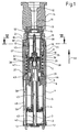
- Fig. 1 denotes a pressing cylinder, in which in the drawing underside bottom 2, a cooling air pipe 3 is arranged.
- a piston 4 is slidably guided, within which hollow piston rod 5, the cooling air pipe 3 extends.
- the piston rod 5 is radially guided in an intermediate ring 6, which is clamped axially between a stamp cylinder 7 and a head ring 8 forming the upper end of the pressing cylinder 1.
- the stamp cylinder 7 extends coaxially with the press cylinder 1.
- the top side of the piston rod 5 in the drawing is in a manner to be explained in more detail with a press ram 9 in connection, which is otherwise guided centrally within a charging socket 10.
- Denoted by 11 is a per se known, longitudinally divided, a mold cavity 12 enclosing preform, the underside of a likewise longitudinally split formed necking tool 13 surrounds, which in turn surrounds an undivided trained guide ring 14.
- the necking tool 13 is held in an in turn longitudinally formed necking tool holder 15.
- the overall system consisting of muzzle tool holder 15, guide ring 14 and muzzle tool 13 is aligned coaxially with the axis 16 of the mold cavity 12.
- a bearing ring 17, within which the charging socket 10 is guided, is supported on the stamp cylinder 7 via an intermediate disk 18 and fixed in this position by means of a head ring 19.
- the head ring 19 is in turn superimposed by a cover ring 20, the system is secured to the facing side of the head ring 19 by means of a retaining ring 21.
- the fixing of the head ring 19 on the stamp cylinder 7 is given by screws 22 which are formed in the outer periphery of the bearing ring 17, penetrate approximately semicircular recesses 23. Between the screws 22 and the bearing ring 17 is always a radial clearance.
- Fig. 6 shows this radial clearance 24 between the inside of the bearing ring 17 and the outside of an integrally formed on the bearing ring outer flange 17 ', via which rests on the facing end face of the intermediate disc 18.
- the inner contours of the head ring 19 form a bearing gap 19 'of the stamp cylinder 7, within which the bearing ring 17 is radially displaceable on all sides.
- Fig. 4 can recognize, ends the upper-side end of the piston rod 5 in a coaxial with the punch cylinder 7 extending threaded bore 25 into which a coupling head 26 is screwed.
- a circumferential groove 27 is formed, which extends coaxially to the axis 7 'of the stamp cylinder 7 and with a radially inwardly extending inner flange 28 (FIG. Fig. 5 ) of a longitudinally split coupling ring 29, also called split ring 29, is engaged.
- Fig. 5 reveals the split ring 29 has a global ring-cylindrical shape, on the underside of said inner flange 28 is formed, wherein radially inwardly an annular groove 30 is provided, which in turn is in engagement with a flange 31 of the ram 9.
- the press ram 9 forms at its designated by the flange 31 portion a cylindrical part which serves to receive a retaining ring 32, the upper side via a spring 33, e.g. a plate spring, is supported on the ram 9 and whose position is defined on the underside by a locking ring 34.
- a spring 33 e.g. a plate spring
- a stop ring 35 which surrounds the charging socket 10, and via which the bearing ring 17 is axially supported on a molded-on to the charging socket 10 outer flange 36.
- the lower end in all drawing figures of the charging socket 10 is received within a support sleeve 37, wherein a return spring 38 is supported at its one end on a molded on the support sleeve 37 outer flange 39 and at its other end to the stop ring 35 opposite side of the outer flange 36 ,
- the retaining ring 32 protrudes with a central cylindrical projection 32 'into the coupling head 26 and thus into the piston rod 5.
- said spring 33 is given in this way an elastically biased, sealing engagement of the retaining ring 32 at an outermost annular surface of the coupling head 26. It is essential that the projection 32 'within the coupling head 26 is radially displaceable on all sides.
- the charging socket 10 further forms at its lower end a radially inwardly extending inner flange 40, on which a disposed within the charging socket 10 spacer bushing 41 rests.
- This spacer 41 will be explained below.
- the support bush 37 is radially slidably supported on the intermediate ring 6 of the pressing cylinder 1 below.
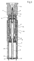
- a cooling tube 44 is provided within the press ram 9, which extends at a distance within the press ram 9 and with openings 9 '(FIG. Fig. 5 ) is provided. Through these openings 9 ', the cooling air enters into a gap 45 between the cooling tube 44 and the inner wall of the ram 9, to this then via line elements 46 (FIG. Fig.
- the bottom 2 of the pressing cylinder 1 thus includes connection organs for the supply and the discharge of cooling air.
- the piston 4 can be acted upon on both sides. With 51 and 52 port openings are designated for compressed air, which are acted upon or vented in accordance with the desired direction of movement of the piston 4 with pressurized fluid.
- the pressing cylinder 1, the piston 4, as well as the stamp cylinder 7 form a, by its axis 7 'marked machine-fixed assembly according to the invention does not participate in radial compensating movements for the purpose of centering against the preform 11.
- the ram 9, the split ring 29, the charging socket 10, the bearing ring 17, the stop ring 35, the spacer bushing 41, the support bushing 37 and the return spring 38 form a characterized by its axis 10 'assembly, the radially in accordance with the design predetermined game dimensions relative to the axis 16 of the preform 11 is adjustable.
- An adjustment in this sense Thus, it is practically a parallel displacement of the axle 10 'with respect to the axle 7', as well as an alignment of the axles 10 'and 16.
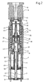
- the return spring 38 is in this phase of operation under elastic compression bias and holds the charging socket 10 via its annular flange 36 in abutment against the stop ring 35. This position is secured by applying the top of the piston 4.
- the top of the piston 4 is vented, so that the piston rod 5 under the action of the return spring 38 in the in Fig. 2 shown position moves.
- the loading position is characterized in that due to an upward movement of the piston rod 5 in the direction of arrow 53, the relaxing return spring 38 via the annular flange 36 has a driving effect on the charging socket 10, until the stop ring 35 on the facing annular surface 17 "of the bearing ring 17th The stop ring 35 thus restricts the upward movement of the charging socket 10, which has been introduced in the loading position by a defined amount into the necking tool 13.
- the loading bushing 10 and with it also the pressing punches 9 are centered, specifically with respect to the axis 16 of the mold cavity 12th
- the charging socket 10 is provided with its free, provided with a chamfer 10 "end with a radial sliding fit into the closed necking tool 13th insertable.
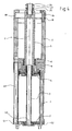
- a possible misalignment between the axes of the charging socket 10 and the press ram 9 relative to the axis 16 is thereby compensated that, as in particular in Fig. 6 shown, a radial clearance between the outside of the outer flange 17 'of the bearing ring 17 and the inside of the head ring 19, which allows in accordance with this game a radial displacement of the charging socket 10 relative to the axis 7' of the stamp cylinder 7.
- a radial clearance also exists between the radial outer sides of the outer flange 39 and the stop ring 35 relative to the radially inner side of the stamp cylinder 7. It can be seen that the assembly, consisting essentially of the ram 9, the bearing ring 17, the stop ring 35, the charging socket 10 and the support bush 37 is radially adjustable, in accordance with the above-mentioned radial clearances.
- a retraction of the press ram 9 can be done by pressurizing the top of the piston 4 via the connection opening 52, whereupon the piston 4 again in his in Fig. 1 reproduced lowest position is transferred, in which the ram 9 in turn via the spacer ring 41, the charging socket 10 and the support sleeve 37 on the intermediate ring 6 and thus the pressing cylinder 1 is supported.
- each press ram 9 together with the charging socket 10 can be centered individually, so that misalignment of the individual ram or the mold can be optimally taken into account.
Landscapes
- Engineering & Computer Science (AREA)
- Chemical & Material Sciences (AREA)
- Mechanical Engineering (AREA)
- Manufacturing & Machinery (AREA)
- Materials Engineering (AREA)
- Organic Chemistry (AREA)
- Automatic Assembly (AREA)
- Forging (AREA)
- Processing And Handling Of Plastics And Other Materials For Molding In General (AREA)
Claims (8)
- Station à moule ébaucheur d'une machine à façonner le verre en pressé-soufflé, comprenant un moule ébaucheur (11) avec un axe (16), un outil d'embouchure (13) divisé en longueur et déplaçable en va-et-vient entre la station à moule ébaucheur et une station à moule finisseur de la machine à façonner le verre en pressé-soufflé, et un mécanisme à poinçon ébaucheur, ledit mécanisme à poinçon ébaucheur comportant :un cylindre de compression (1) avec un piston (4) pouvant subir la pression d'un fluide hydraulique sur l'un ou l'autre de ses côtés au choix, et une tige de piston (5) s'étendant en direction du moule ébaucheur (11) depuis le cylindre de compression (1),un cylindre à poinçon (7) fixé coaxialement par rapport au cylindre de compression (1) et entourant une extrémité supérieure de la tige de piston (5), etune bague fendue (29) pouvant être accouplée avec une extrémité libre de la tige de piston (5) d'un côté, et avec une bride (31) d'un poinçon ébaucheur (9) de l'autre côté, divisée en longueur et coulissant en va-et-vient dans une douille de chargement (10),la douille de chargement (10) étant déplaçable par la tige de piston (5) vers une position initiale distante au maximum du moule ébaucheur (11), contre la force d'un ressort de rappel (38),et la douille de chargement (10) étant déplaçable jusque vers une position de travail en butée contre le cylindre à poinçon (7), en cas de déplacement de la tige de piston (5) dans la direction opposée par le ressort de rappel (38)caractérisée
en ce qu'une première unité modulaire avec un axe longitudinal (7'), comprenant essentiellement le cylindre de compression (1), le piston (4), une tête d'accouplement (26) en liaison avec le piston (4), vissée sur l'extrémité libre de la tige de piston (5), une bague de tête (19), la tige de piston (5) et le cylindre à poinçon (7), est fixement disposée sur la machine,
en ce que pour l'alignement du poinçon ébaucheur (9) par rapport à l'axe (16) de l'outil d'embouchure (13) et du moule ébaucheur (11), une deuxième unité modulaire est déplaçable transversalement à l'axe longitudinal (7') de la première unité modulaire et par rapport à la première unité modulaire,
la deuxième unité modulaire comprenant essentiellement la bague fendue (29), le poinçon ébaucheur (9), la douille de chargement (10), une bague de palier (17) entourant la douille de chargement (10), une bague de maintien (32) maintenant le poinçon ébaucheur (9) à l'intérieur de la bague fendue (29), une douille de support (37) entourant la douille de chargement (10), une bague de butée (35) entourant la douille de chargement (10) et limitant le déplacement de la douille de chargement (10) par rapport à la douille de support (37), ainsi que le ressort de rappel (38),
un jeu radial étant ajusté pour l'obtention d'une mobilité de la deuxième unité modulaire par rapport à la première unité modulaire dans un sens transversal à l'axe longitudinal (7'), entre la bague de palier (17) et les contours de la bague de tête (19) recevant celle-ci, une bride intérieure (28) formée sur la bague fendue (29) et une rainure périphérique (27) de la tête d'accouplement (26), un épaulement (32') de la bague de maintien (32) et la tête d'accouplement (26) ainsi qu'entre une face radiale extérieure d'une bride extérieure (39) de la douille de support (37) et de la bague de butée (35) par rapport à la face radiale intérieure du cylindre à poinçon (7), et
en ce que la deuxième unité modulaire peut être alignée par rapport à la première unité modulaire à la suite d'un déplacement de la douille de chargement (10) de ladite position initiale, où elle n'est pas en prise avec l'outil d'embouchure (13), vers l'intérieur de l'outil d'embouchure (13), la douille de chargement (10) s'engageant, dans sa position de travail, par une extrémité libre avec un ajustement glissant radial dans une extrémité libre de l'outil d'embouchure (13) fermé, et l'extrémité libre de la douille de chargement (10) et/ou l'extrémité libre de l'outil d'embouchure (13) présentant un biseau (10") sur le côté opposé pour faciliter la pénétration de centrage de la douille de chargement (10) dans l'outil d'embouchure (13) fermé. - Station à moule ébaucheur selon la revendication 1, caractérisée en ce qu'une partie de la douille de chargement (10) opposée au moule ébaucheur (11) est montée de manière à être déplaçable dans la bague de palier (17) de la deuxième unité modulaire, et en ce que la bague de palier (17) comporte une bride extérieure (17') radialement déplaçable omnidirectionnellement avec un ajustement glissant radial dans une fente de palier (19') du cylindre à poinçon (7).
- Station à moule ébaucheur selon la revendication 2, caractérisée en ce qu'une face de la bride extérieure (36) repose contre la bague de butée (35) coopérant avec la bague de palier (17), et en ce que le ressort de rappel (38) s'appuie sur la face opposée de la bride extérieure (36).
- Station à moule ébaucheur selon l'une des revendications 1 à 3, caractérisée en ce qu'une partie de la douille de chargement (10) distante du moule ébaucheur (11) est déplaçable dans la douille de support (37) de la deuxième unité modulaire, en ce que le ressort de rappel (38) s'appuie sur une bride extérieure (39) de la douille de support (37), et en ce que la douille de support (37) s'appuie de manière à être radialement coulissante sur une bague intercalaire (6) du cylindre de compression (1) qui entoure la tige de piston (5).
- Station à moule ébaucheur selon l'une des revendications 1 à 4, caractérisée en ce qu'une bride (31) du poinçon ébaucheur (9) est serrée dans la bague fendue (29) fermée, et en ce que la bague fendue (29) fermée est guidée avec un ajustement glissant radial dans un alésage de la douille de chargement (10).
- Station à moule ébaucheur selon l'une des revendications 1 à 5, caractérisée en ce que le poinçon ébaucheur (9) comporte une cavité, en ce qu'un conduit de refroidissement (44) pourvu de perforations (9') s'étend dans la cavité, en ce que le conduit de refroidissement (44) comporte à son extrémité libre une bague de maintien (32) coulissante, axialement déplaçable dans un alésage de la bride (31) du poinçon ébaucheur (9), et en ce que la bague de maintien (32) est pré-contrainte par un ressort (33) s'appuyant sur la bride (31) du poinçon ébaucheur (9), en contact d'étanchéité avec une surface annulaire extérieure de la tige de piston (5) pourvue d'un perçage axial.
- Station à moule ébaucheur selon la revendication 6, caractérisée en ce que l'épaulement (32') formé sur la bague de maintien (32) est de forme tubulaire, et en ce que ledit épaulement s'étend dans le perçage de la tige de piston avec un jeu radial omnidirectionnel.
- Station à moule ébaucheur selon l'une des revendications 1 à 7, caractérisée en ce qu'une bride intérieure (40) est prévue à une extrémité de la douille de chargement (10) distante du moule ébaucheur (11), et en ce qu'une douille d'écartement (41) d'une longueur axiale sélectionnable est disposée entre la bride intérieure (40) et la bague fendue (29).
Applications Claiming Priority (2)
| Application Number | Priority Date | Filing Date | Title |
|---|---|---|---|
| DE200420003097 DE202004003097U1 (de) | 2004-02-28 | 2004-02-28 | Vorformstation einer Press-Blas-Glasformmaschine |
| DE202004003097U | 2004-02-28 |
Publications (3)
| Publication Number | Publication Date |
|---|---|
| EP1568663A2 EP1568663A2 (fr) | 2005-08-31 |
| EP1568663A3 EP1568663A3 (fr) | 2006-07-26 |
| EP1568663B1 true EP1568663B1 (fr) | 2012-08-15 |
Family
ID=32240912
Family Applications (1)
| Application Number | Title | Priority Date | Filing Date |
|---|---|---|---|
| EP20040027162 Expired - Lifetime EP1568663B1 (fr) | 2004-02-28 | 2004-11-16 | Station de préformage d'une machine préssée-soufflée |
Country Status (2)
| Country | Link |
|---|---|
| EP (1) | EP1568663B1 (fr) |
| DE (1) | DE202004003097U1 (fr) |
Cited By (1)
| Publication number | Priority date | Publication date | Assignee | Title |
|---|---|---|---|---|
| DE102017123216A1 (de) | 2016-10-07 | 2018-04-12 | Manuel Ecker | Formwerkzeug sowie Pressstempel für eine Glasformmaschine mit 3D-gedruckten Kühlkanälen |
Families Citing this family (2)
| Publication number | Priority date | Publication date | Assignee | Title |
|---|---|---|---|---|
| DE102005001065A1 (de) * | 2005-01-07 | 2006-07-20 | Gps Glasproduktions-Service Gmbh | Vor- bzw. Fertigform einer Glasmaschine |
| DE102014011310B4 (de) | 2014-08-04 | 2021-04-15 | Heye International Gmbh | Verfahren und Vorrichtung zur Verbesserung der Sicherheit des Betriebsablaufs einer Glasformmaschine |
Family Cites Families (5)
| Publication number | Priority date | Publication date | Assignee | Title |
|---|---|---|---|---|
| SE353519B (fr) | 1969-08-19 | 1973-02-05 | Emhart Corp | |
| DE3638677A1 (de) | 1986-11-12 | 1988-05-26 | Heye Hermann Fa | Vorrichtung zur fuehrung eines pressstempels einer i.s.-glasformmaschine |
| JPH11209129A (ja) * | 1998-01-26 | 1999-08-03 | Nihon Yamamura Glass Co Ltd | 中空容器成形方法およびその装置 |
| US6286339B1 (en) * | 2000-01-28 | 2001-09-11 | Owens-Brockway Glass Container Inc. | Glass container forming machine plunger assembly |
| US7073352B2 (en) * | 2002-03-07 | 2006-07-11 | Vitro Global, S.A. | Method and a machine for the production of hollow glassware articles |
-
2004
- 2004-02-28 DE DE200420003097 patent/DE202004003097U1/de not_active Expired - Lifetime
- 2004-11-16 EP EP20040027162 patent/EP1568663B1/fr not_active Expired - Lifetime
Cited By (1)
| Publication number | Priority date | Publication date | Assignee | Title |
|---|---|---|---|---|
| DE102017123216A1 (de) | 2016-10-07 | 2018-04-12 | Manuel Ecker | Formwerkzeug sowie Pressstempel für eine Glasformmaschine mit 3D-gedruckten Kühlkanälen |
Also Published As
| Publication number | Publication date |
|---|---|
| EP1568663A3 (fr) | 2006-07-26 |
| DE202004003097U1 (de) | 2004-04-29 |
| EP1568663A2 (fr) | 2005-08-31 |
Similar Documents
| Publication | Publication Date | Title |
|---|---|---|
| DE112009000772B4 (de) | Doppelt geschlossener hydraulischer Werkzeugträger | |
| EP0125488B1 (fr) | Dispositif de refroidissement pour un outil de forme pour le façonnage de verre ou d'autres matériaux thermo-plastiques | |
| DE3044137A1 (de) | Formschliesseinheit fuer kunststoff-spritzgiessmaschine | |
| DE10100868B4 (de) | Kaltwalz-Umformmaschine und Werkzeug zum Herstellen von flanschförmigen Erzeugnissen bzw. von Flanschen aus einem zylindrischen Vorprodukt | |
| DE2415549B2 (de) | Vorrichtung für die spanlose Kaltverformung eines Rohlings | |
| DE60216750T2 (de) | Doppeltwirkende bodenformvorrichtung für betrieb mit hohem arbeitstakt | |
| DE68915467T2 (de) | Oeffnungs- und Schliessmechanismus für eine J.-S.-Glasformmaschine. | |
| EP1664488B1 (fr) | Piston creux destine a une machine a pistons et procede de fabrication d'un piston creux | |
| DE19962607B4 (de) | Werkzeugkassette mit federnder Matrize | |
| EP1568663B1 (fr) | Station de préformage d'une machine préssée-soufflée | |
| EP1023132B1 (fr) | Systeme d'entrainement hydraulique pour presse a forger ou coulisseaux de machine a forger | |
| EP1129039A1 (fr) | Procede et dispositif pour presser une ebauche | |
| DE10056610A1 (de) | Vorrichtung zur Innenhochdruck-Umformung von Hohlkörpern | |
| WO2018210444A1 (fr) | Module de poinçon pour une machine à former le verre | |
| EP0002032B1 (fr) | Procédé et dispositif de fabrication de poulies multigorges | |
| EP3357640B1 (fr) | Module porte-outils à action translatoire destiné au finissage | |
| EP1764173A2 (fr) | Dispositif pour mouler de la poudre par pression | |
| DE3637552C1 (en) | Device for cooling a mouth mould (neck ring) of a glass-moulding machine | |
| DE19647536C1 (de) | Vorformstation einer Preß-Blase-Glasformmaschine | |
| DE102005027032B4 (de) | Vorrichtung zum Herstellen eines Formteils | |
| DE1223257B (de) | Pneumatischer Dreistellungs-Arbeitszylinder | |
| DE3025333A1 (de) | Vorrichtung zum formen von kuelbeln zur herstellung von enghalsigen glaswaren nach dem press-blas-verfahren | |
| EP1681275B1 (fr) | Mécanisme de poinçon-ébaucheur d'une machine de moulage de verre | |
| DE2755495C2 (fr) | ||
| EP1260487B1 (fr) | Tête de soufflage |
Legal Events
| Date | Code | Title | Description |
|---|---|---|---|
| PUAI | Public reference made under article 153(3) epc to a published international application that has entered the european phase |
Free format text: ORIGINAL CODE: 0009012 |
|
| AK | Designated contracting states |
Kind code of ref document: A2 Designated state(s): AT BE BG CH CY CZ DE DK EE ES FI FR GB GR HU IE IS IT LI LU MC NL PL PT RO SE SI SK TR |
|
| AX | Request for extension of the european patent |
Extension state: AL HR LT LV MK YU |
|
| PUAL | Search report despatched |
Free format text: ORIGINAL CODE: 0009013 |
|
| AK | Designated contracting states |
Kind code of ref document: A3 Designated state(s): AT BE BG CH CY CZ DE DK EE ES FI FR GB GR HU IE IS IT LI LU MC NL PL PT RO SE SI SK TR |
|
| AX | Request for extension of the european patent |
Extension state: AL HR LT LV MK YU |
|
| 17P | Request for examination filed |
Effective date: 20061202 |
|
| AKX | Designation fees paid |
Designated state(s): AT BE BG CH CY CZ DE DK EE ES FI FR GB GR HU IE IS IT LI LU MC NL PL PT RO SE SI SK TR |
|
| 17Q | First examination report despatched |
Effective date: 20070418 |
|
| GRAP | Despatch of communication of intention to grant a patent |
Free format text: ORIGINAL CODE: EPIDOSNIGR1 |
|
| GRAS | Grant fee paid |
Free format text: ORIGINAL CODE: EPIDOSNIGR3 |
|
| GRAA | (expected) grant |
Free format text: ORIGINAL CODE: 0009210 |
|
| AK | Designated contracting states |
Kind code of ref document: B1 Designated state(s): AT BE BG CH CY CZ DE DK EE ES FI FR GB GR HU IE IS IT LI LU MC NL PL PT RO SE SI SK TR |
|
| REG | Reference to a national code |
Ref country code: CH Ref legal event code: EP Ref country code: GB Ref legal event code: FG4D Free format text: NOT ENGLISH Ref country code: AT Ref legal event code: REF Ref document number: 570719 Country of ref document: AT Kind code of ref document: T Effective date: 20120815 |
|
| REG | Reference to a national code |
Ref country code: DE Ref legal event code: R082 Ref document number: 502004013692 Country of ref document: DE Representative=s name: SOBISCH & KRAMM, DE |
|
| REG | Reference to a national code |
Ref country code: CH Ref legal event code: NV Representative=s name: BOHEST AG |
|
| REG | Reference to a national code |
Ref country code: IE Ref legal event code: FG4D Free format text: LANGUAGE OF EP DOCUMENT: GERMAN |
|
| REG | Reference to a national code |
Ref country code: SE Ref legal event code: TRGR |
|
| REG | Reference to a national code |
Ref country code: DE Ref legal event code: R096 Ref document number: 502004013692 Country of ref document: DE Effective date: 20121018 |
|
| REG | Reference to a national code |
Ref country code: NL Ref legal event code: VDEP Effective date: 20120815 |
|
| PG25 | Lapsed in a contracting state [announced via postgrant information from national office to epo] |
Ref country code: FI Free format text: LAPSE BECAUSE OF FAILURE TO SUBMIT A TRANSLATION OF THE DESCRIPTION OR TO PAY THE FEE WITHIN THE PRESCRIBED TIME-LIMIT Effective date: 20120815 Ref country code: CY Free format text: LAPSE BECAUSE OF FAILURE TO SUBMIT A TRANSLATION OF THE DESCRIPTION OR TO PAY THE FEE WITHIN THE PRESCRIBED TIME-LIMIT Effective date: 20120815 Ref country code: IS Free format text: LAPSE BECAUSE OF FAILURE TO SUBMIT A TRANSLATION OF THE DESCRIPTION OR TO PAY THE FEE WITHIN THE PRESCRIBED TIME-LIMIT Effective date: 20121215 |
|
| PG25 | Lapsed in a contracting state [announced via postgrant information from national office to epo] |
Ref country code: PT Free format text: LAPSE BECAUSE OF FAILURE TO SUBMIT A TRANSLATION OF THE DESCRIPTION OR TO PAY THE FEE WITHIN THE PRESCRIBED TIME-LIMIT Effective date: 20121217 Ref country code: GR Free format text: LAPSE BECAUSE OF FAILURE TO SUBMIT A TRANSLATION OF THE DESCRIPTION OR TO PAY THE FEE WITHIN THE PRESCRIBED TIME-LIMIT Effective date: 20121116 Ref country code: SI Free format text: LAPSE BECAUSE OF FAILURE TO SUBMIT A TRANSLATION OF THE DESCRIPTION OR TO PAY THE FEE WITHIN THE PRESCRIBED TIME-LIMIT Effective date: 20120815 Ref country code: PL Free format text: LAPSE BECAUSE OF FAILURE TO SUBMIT A TRANSLATION OF THE DESCRIPTION OR TO PAY THE FEE WITHIN THE PRESCRIBED TIME-LIMIT Effective date: 20120815 |
|
| PG25 | Lapsed in a contracting state [announced via postgrant information from national office to epo] |
Ref country code: NL Free format text: LAPSE BECAUSE OF FAILURE TO SUBMIT A TRANSLATION OF THE DESCRIPTION OR TO PAY THE FEE WITHIN THE PRESCRIBED TIME-LIMIT Effective date: 20120815 |
|
| PG25 | Lapsed in a contracting state [announced via postgrant information from national office to epo] |
Ref country code: DK Free format text: LAPSE BECAUSE OF FAILURE TO SUBMIT A TRANSLATION OF THE DESCRIPTION OR TO PAY THE FEE WITHIN THE PRESCRIBED TIME-LIMIT Effective date: 20120815 Ref country code: RO Free format text: LAPSE BECAUSE OF FAILURE TO SUBMIT A TRANSLATION OF THE DESCRIPTION OR TO PAY THE FEE WITHIN THE PRESCRIBED TIME-LIMIT Effective date: 20120815 Ref country code: ES Free format text: LAPSE BECAUSE OF FAILURE TO SUBMIT A TRANSLATION OF THE DESCRIPTION OR TO PAY THE FEE WITHIN THE PRESCRIBED TIME-LIMIT Effective date: 20121126 Ref country code: EE Free format text: LAPSE BECAUSE OF FAILURE TO SUBMIT A TRANSLATION OF THE DESCRIPTION OR TO PAY THE FEE WITHIN THE PRESCRIBED TIME-LIMIT Effective date: 20120815 |
|
| BERE | Be: lapsed |
Owner name: HEYE INTERNATIONAL G.M.B.H. Effective date: 20121130 |
|
| PG25 | Lapsed in a contracting state [announced via postgrant information from national office to epo] |
Ref country code: SK Free format text: LAPSE BECAUSE OF FAILURE TO SUBMIT A TRANSLATION OF THE DESCRIPTION OR TO PAY THE FEE WITHIN THE PRESCRIBED TIME-LIMIT Effective date: 20120815 |
|
| PLBE | No opposition filed within time limit |
Free format text: ORIGINAL CODE: 0009261 |
|
| STAA | Information on the status of an ep patent application or granted ep patent |
Free format text: STATUS: NO OPPOSITION FILED WITHIN TIME LIMIT |
|
| 26N | No opposition filed |
Effective date: 20130516 |
|
| PG25 | Lapsed in a contracting state [announced via postgrant information from national office to epo] |
Ref country code: BG Free format text: LAPSE BECAUSE OF FAILURE TO SUBMIT A TRANSLATION OF THE DESCRIPTION OR TO PAY THE FEE WITHIN THE PRESCRIBED TIME-LIMIT Effective date: 20121115 |
|
| REG | Reference to a national code |
Ref country code: IE Ref legal event code: MM4A |
|
| PG25 | Lapsed in a contracting state [announced via postgrant information from national office to epo] |
Ref country code: BE Free format text: LAPSE BECAUSE OF NON-PAYMENT OF DUE FEES Effective date: 20121130 |
|
| REG | Reference to a national code |
Ref country code: DE Ref legal event code: R097 Ref document number: 502004013692 Country of ref document: DE Effective date: 20130516 |
|
| PG25 | Lapsed in a contracting state [announced via postgrant information from national office to epo] |
Ref country code: IE Free format text: LAPSE BECAUSE OF NON-PAYMENT OF DUE FEES Effective date: 20121116 |
|
| REG | Reference to a national code |
Ref country code: AT Ref legal event code: MM01 Ref document number: 570719 Country of ref document: AT Kind code of ref document: T Effective date: 20121130 |
|
| PG25 | Lapsed in a contracting state [announced via postgrant information from national office to epo] |
Ref country code: AT Free format text: LAPSE BECAUSE OF NON-PAYMENT OF DUE FEES Effective date: 20121130 |
|
| PGFP | Annual fee paid to national office [announced via postgrant information from national office to epo] |
Ref country code: CH Payment date: 20131122 Year of fee payment: 10 Ref country code: SE Payment date: 20131122 Year of fee payment: 10 Ref country code: CZ Payment date: 20131106 Year of fee payment: 10 Ref country code: FR Payment date: 20131119 Year of fee payment: 10 |
|
| PGFP | Annual fee paid to national office [announced via postgrant information from national office to epo] |
Ref country code: IT Payment date: 20131126 Year of fee payment: 10 |
|
| PG25 | Lapsed in a contracting state [announced via postgrant information from national office to epo] |
Ref country code: MC Free format text: LAPSE BECAUSE OF NON-PAYMENT OF DUE FEES Effective date: 20121130 Ref country code: TR Free format text: LAPSE BECAUSE OF FAILURE TO SUBMIT A TRANSLATION OF THE DESCRIPTION OR TO PAY THE FEE WITHIN THE PRESCRIBED TIME-LIMIT Effective date: 20120815 |
|
| PG25 | Lapsed in a contracting state [announced via postgrant information from national office to epo] |
Ref country code: LU Free format text: LAPSE BECAUSE OF NON-PAYMENT OF DUE FEES Effective date: 20121116 |
|
| PG25 | Lapsed in a contracting state [announced via postgrant information from national office to epo] |
Ref country code: HU Free format text: LAPSE BECAUSE OF FAILURE TO SUBMIT A TRANSLATION OF THE DESCRIPTION OR TO PAY THE FEE WITHIN THE PRESCRIBED TIME-LIMIT Effective date: 20041116 |
|
| REG | Reference to a national code |
Ref country code: CH Ref legal event code: PCAR Free format text: NEW ADDRESS: HOLBEINSTRASSE 36-38, 4051 BASEL (CH) |
|
| REG | Reference to a national code |
Ref country code: SE Ref legal event code: EUG Ref country code: CH Ref legal event code: PL |
|
| PG25 | Lapsed in a contracting state [announced via postgrant information from national office to epo] |
Ref country code: LI Free format text: LAPSE BECAUSE OF NON-PAYMENT OF DUE FEES Effective date: 20141130 Ref country code: SE Free format text: LAPSE BECAUSE OF NON-PAYMENT OF DUE FEES Effective date: 20141117 Ref country code: CH Free format text: LAPSE BECAUSE OF NON-PAYMENT OF DUE FEES Effective date: 20141130 Ref country code: CZ Free format text: LAPSE BECAUSE OF NON-PAYMENT OF DUE FEES Effective date: 20141116 |
|
| REG | Reference to a national code |
Ref country code: FR Ref legal event code: ST Effective date: 20150731 |
|
| PG25 | Lapsed in a contracting state [announced via postgrant information from national office to epo] |
Ref country code: FR Free format text: LAPSE BECAUSE OF NON-PAYMENT OF DUE FEES Effective date: 20141201 |
|
| PG25 | Lapsed in a contracting state [announced via postgrant information from national office to epo] |
Ref country code: IT Free format text: LAPSE BECAUSE OF NON-PAYMENT OF DUE FEES Effective date: 20141116 |
|
| PGFP | Annual fee paid to national office [announced via postgrant information from national office to epo] |
Ref country code: GB Payment date: 20151123 Year of fee payment: 12 |
|
| GBPC | Gb: european patent ceased through non-payment of renewal fee |
Effective date: 20161116 |
|
| PG25 | Lapsed in a contracting state [announced via postgrant information from national office to epo] |
Ref country code: GB Free format text: LAPSE BECAUSE OF NON-PAYMENT OF DUE FEES Effective date: 20161116 |
|
| PGFP | Annual fee paid to national office [announced via postgrant information from national office to epo] |
Ref country code: DE Payment date: 20181205 Year of fee payment: 15 |
|
| REG | Reference to a national code |
Ref country code: DE Ref legal event code: R119 Ref document number: 502004013692 Country of ref document: DE |
|
| PG25 | Lapsed in a contracting state [announced via postgrant information from national office to epo] |
Ref country code: DE Free format text: LAPSE BECAUSE OF NON-PAYMENT OF DUE FEES Effective date: 20200603 |