EP1568542B1 - Porte-vélo(s) comportant une partie apte à être repliée transversalement - Google Patents
Porte-vélo(s) comportant une partie apte à être repliée transversalement Download PDFInfo
- Publication number
- EP1568542B1 EP1568542B1 EP05300138A EP05300138A EP1568542B1 EP 1568542 B1 EP1568542 B1 EP 1568542B1 EP 05300138 A EP05300138 A EP 05300138A EP 05300138 A EP05300138 A EP 05300138A EP 1568542 B1 EP1568542 B1 EP 1568542B1
- Authority
- EP
- European Patent Office
- Prior art keywords
- bicycle
- mounting part
- bracket
- longitudinal
- bicycle carrier
- Prior art date
- Legal status (The legal status is an assumption and is not a legal conclusion. Google has not performed a legal analysis and makes no representation as to the accuracy of the status listed.)
- Not-in-force
Links
- 230000000295 complement effect Effects 0.000 claims description 8
- 230000000630 rising effect Effects 0.000 claims 2
- 230000013011 mating Effects 0.000 claims 1
- 239000000969 carrier Substances 0.000 description 2
- 238000004873 anchoring Methods 0.000 description 1
- 238000012423 maintenance Methods 0.000 description 1
Images


Classifications
-
- B—PERFORMING OPERATIONS; TRANSPORTING
- B60—VEHICLES IN GENERAL
- B60R—VEHICLES, VEHICLE FITTINGS, OR VEHICLE PARTS, NOT OTHERWISE PROVIDED FOR
- B60R9/00—Supplementary fittings on vehicle exterior for carrying loads, e.g. luggage, sports gear or the like
- B60R9/08—Supplementary fittings on vehicle exterior for carrying loads, e.g. luggage, sports gear or the like specially adapted for sports gear
- B60R9/10—Supplementary fittings on vehicle exterior for carrying loads, e.g. luggage, sports gear or the like specially adapted for sports gear for cycles
-
- B—PERFORMING OPERATIONS; TRANSPORTING
- B60—VEHICLES IN GENERAL
- B60R—VEHICLES, VEHICLE FITTINGS, OR VEHICLE PARTS, NOT OTHERWISE PROVIDED FOR
- B60R9/00—Supplementary fittings on vehicle exterior for carrying loads, e.g. luggage, sports gear or the like
- B60R9/06—Supplementary fittings on vehicle exterior for carrying loads, e.g. luggage, sports gear or the like at vehicle front or rear
Definitions
- the invention provides a bicycle carrier (s) for transporting at least one bike to the rear of a vehicle, which can be folded transversely when not in use.
- the invention more particularly proposes a bicycle carrier (s) for fixing at least one bicycle to the rear of a motor vehicle, with its frame extending in a generally vertical transverse orientation, of the type comprising a support structure which is attached to the vehicle, which comprises two lower longitudinal arms distributed on either side of a median vertical longitudinal plane of the support structure and which delimit the general transverse bulk of the support structure, and means for securing the bicycle to the support structure, which comprise in particular a lower support associated with each wheel of the bicycle which is mounted on one of the lower longitudinal arms and which delimits an open housing in its upper part and which receives a lower portion of the associated wheel .
- bike carrier that are mounted on the roof of the vehicle
- bike carriers that the we ride to the rear of the vehicle.
- Bicycle carriers (s) that are mounted at the rear of a motor vehicle mainly comprise a support structure which consists of an assembly of section sections, and means for attaching one or more bicycles to the structure of the vehicle. support.
- the support structure comprises a first set of profile sections which extend in a horizontal plane, and which carry supports which each receive a portion of a wheel of a bicycle.
- the support structure also comprises a second set of section sections which extend in a transverse vertical plane situated at the rear of the vehicle, and which bear means for connecting the frame of each bike to the support structure.
- the support structure thus occupies a particularly large volume because its dimensions must be adapted to the dimensions of the bicycles that it must support.
- the bike carrier (s) is generally detached from the rear of the vehicle to be stored either in a garage or in the rear luggage compartment of the vehicle.
- the elements of the support structure always retain the same transverse size which is generally equal to the length of the bicycle.
- the document DE-A-4407477 discloses a bicycle carrier (s) for which each lower support is pivotally mounted relative to the longitudinal arm on which it is mounted.
- the bicycle carrier (s) has two additional longitudinal arms to lock the supports in the deployed position and in the folded position.
- the invention aims to provide a bicycle carrier (s) which comprises a support structure which it is possible to reduce at least its transverse size, to allow storage of the bike carrier (s) at least inside the rear luggage compartment of the vehicle.
- the invention provides a bicycle carrier (s) of the type described above, characterized in that at least a portion of each support is movable relative to the longitudinal arm associated, between an extended position in which the support is adapted to receive a portion of the associated wheel of the bicycle and wherein said movable portion of the support projects transversely relative to the associated longitudinal arm towards the outside of the support structure and a folded storage position, wherein said movable portion of the support extends transversely between the two longitudinal arms.
- FIG. 1 a bicycle carrier (s) 10 for mounting several bicycles, here two bicycles, at the rear of a motor vehicle (not shown), so that the frame of each bicycle extends in a transverse vertical plane when it is in the mounted position on the bike carrier (s).
- the carrier (s) 10 comprises a support structure 12 which is fixed to the vehicle, and which consists of an assembly of section sections, and it comprises means for securing each bicycle to the support structure 12.
- the support structure 12 thus comprises a front vertical arch 14, generally trapezoid-shaped extending in a transverse vertical plane, which consists of two uprights 16 inclined relative to the vertical and whose upper ends 16a are interconnected. they have a transverse connection section 18.
- the support structure 12 also comprises a lower support frame 20, which extends horizontally and rearwardly from the vertical hoop 14, and which comprises two longitudinal arms 22 each extending rearwardly from the end lower 16b of an associated upright 16 and whose rear longitudinal ends 22a of the two longitudinal arms 22 are interconnected by a rear crossmember 24.
- the support structure 12 comprises anchoring tabs 26 which extend generally longitudinally forwards from the longitudinal arms, forward with respect to the front bow 14, and whose free front ends 26a cooperate with complementary fastening means 28, which is shown in a simplified manner by a rectangle, and which are carried by a structural element of the motor vehicle (not shown).
- the bike carrier (s) 10 extends behind the vehicle, it masks including the rear traffic lights and the rear license plate of the vehicle (not shown).
- the carrier (s) 10 therefore carries a rear support plate 60, which is mounted on the rear crossmember 24, and which carries a number plate 62 and additional rear signal lights 64, replacing the masked elements, which are important security features.
- the carrier (s) 10 also includes an electrical circuit (not shown) for connecting the additional lights 64 to the associated lights of the vehicle.
- the securing means of each of the bikes to the support structure 12 comprise a locking bar 30 of an associated bicycle in the mounted position on the support structure 12 and lower supports 32, each of which is associated with a wheel of a bike .
- Each locking bar 30 extends generally longitudinally rearwards from an associated upright 16 of the front bow 14, its front end 30a is connected to the associated upright 16 via a strap 34, and its rear end 30b carries a clamp of a tube of the associated bicycle frame.
- Each lower support 32 is mounted on a longitudinal arm 22, and it defines a hollow housing 38 open upwards which is adapted to receive a lower portion of the associated wheel.
- the lower supports 32 are spaced transversely from one another by a distance "d" substantially corresponding to the distance between the wheels of the bicycle.
- the length of a bicycle, and more particularly an adult bicycle, is relatively large compared to the width of the vehicle.
- the distance "d" is then also important, which implies that the transverse size of the carrier (s) 10 is important.
- the carrier (s) 10 according to the invention is designed so that one can reduce its transverse size "T" when no bike is mounted on the carrier (s) 10.
- the support structure 12 is designed so that its transverse size "E", which is delimited by the longitudinal arms 22, is smaller than the spacing distance "d" of the lower supports 32.
- the lower supports 32 extend transversely at least partly outside the support structure 12, projecting from the longitudinal arms 22 and thus define the maximum transverse dimension "T1" of the bicycle carrier (s) 10.
- each lower support 32 has a portion 40 which is movable relative to the longitudinal arm 22 associated between a deployed position in which the movable portion 40 protrudes transversely outwardly of the support structure 12, and a folded position in which the movable portion 40 extends transversely between the two longitudinal arms 22.
- Each of the lower supports 32 also comprises a base 42 which is fixed to the associated longitudinal arm 22, and relative to which the mobile part 40 is movable.
- the minimum transverse space requirement "T2" of the carrier (s) 10 therefore depends mainly on the distance between the longitudinal arms 22, that is to say the transverse space "E" of the support structure 12.
- Figures 2 and 3 a preferred embodiment of a lower support 32 according to the invention, wherein the movable portion 40 is articulated relative to the base 42 about an axis A longitudinal main orientation.
- the mobile part 40 consists of a U-shaped arch comprising in particular two parallel branches 44 whose free ends 44a comprise means of articulation of the mobile part 40 about the longitudinal axis A which cooperate with complementary articulation means of the base 42 associated.
- the articulation of the movable portion 40 with respect to the base 42 is here made by the free ends 44a of the branches 44 which are bent outwards so that they are extended by a longitudinal finger 46, coaxial with the longitudinal axis A hinge.
- Each finger 46 is received in a complementary hole 48 which is made in a support lug 50 of the base 42.
- This support lug 50 extends upwards and in a vertical transverse plane from a horizontal upper face 42s of the base 42.
- the base 42 is a main transverse orientation element, it comprises a longitudinal lower groove 52 which receives the longitudinal arm 22 when the base is in position mounted on the longitudinal arm 22.
- the lower groove 52 is open along a lower generatrix to allow mounting of the base 42 around the longitudinal arm 22 by a vertical downward movement of the base 42 relative to the longitudinal arm 22.
- the base 42 also comprises means (not shown) for securing it with the associated longitudinal arm 22, pivoting about the main axis of the longitudinal arm 22.
- These securing means consist for example of a vertical finger which is received in a complementary hole of the longitudinal arm 22.
- the support 32 delimits a hollow housing 38 open upwards and in which a lower portion of the wheel is placed.
- the hollow housing 38 is delimited in part by the base 42, and partly by the movable part 40.
- the hollow housing 38 is delimited in part by a transverse upper groove 54 of the base 42, which opens into the horizontal upper face 42s of the base and which opens into a longitudinal vertical end external end 42e of the base.
- This upper groove 54 is of concave shape globally complementary to the shape of a bicycle wheel.
- the mobile part 40 also delimits the hollow housing 38 when it is in the deployed position, in cooperation with the upper groove 54 of the base 42.
- the mobile part 40 when the mobile part 40 is in the deployed position, it extends in a horizontal plane so that the branches 44 extend transversely towards the outside by extending the upper groove 54.
- the mobile part 40 and the upper edge of the upper groove 54 define the upper opening of the hollow housing 38, and only the upper groove 54 defines the bottom of the hollow housing 38.
- the base 42 comprises means for holding the mobile part 40 in the deployed position.
- These holding means comprise two vertical legs 56 which extend vertically upwards from the horizontal upper face 42s of the base 42. These vertical legs 56 are distributed symmetrically on either side of a plane transverse vertical transverse base 42, and they are arranged transversely at a distance from the longitudinal axis A articulation of the movable portion 40, that is to say here in the vicinity of the outer transverse end of the base 42.
- the vertical tabs 56 each comprise a transverse groove 58 made in a vertical transverse face 56a of the tab 56.
- each branch 44 is partially received in the associated transverse groove 58, thereby achieving pivotal locking of the movable portion 40.
- the vertical legs 56 are elastically deformable so that they fade during movement of the movable portion 40 to its deployed position.
- the grooves 58 are made in the external transverse vertical faces 56a of the tabs 56, that is to say that the tabs 56 are arranged transversely between the branches 44 of the mobile part 40.
- the invention is not limited to the embodiment which has just been described and that the movable parts 40 may have another structure, and that they may for example each consist of an open profile section towards the top, or they can be mounted sliding transversely relative to the base 42 associated.
- transverse grooves 58 may be made in the internal transverse vertical faces of the tabs 56, that is to say that the tabs 56 are arranged transversely on either side of the movable part 40.
Landscapes
- Engineering & Computer Science (AREA)
- Mechanical Engineering (AREA)
- Motorcycle And Bicycle Frame (AREA)
- Absorbent Articles And Supports Therefor (AREA)
- Carriages For Children, Sleds, And Other Hand-Operated Vehicles (AREA)
- Steering Devices For Bicycles And Motorcycles (AREA)
Description
- L'invention propose un porte-vélo(s) pour le transport d'au moins un vélo à l'arrière d'un véhicule, que l'on peut replier transversalement lorsqu'il n'est pas utilisé.
- L'invention propose plus particulièrement un porte-vélo(s) pour fixer au moins un vélo à l'arrière d'un véhicule automobile, avec son cadre s'étendant selon une orientation globalement verticale transversale, du type comportant une structure de support qui est fixée au véhicule, qui comporte deux bras longitudinaux inférieurs répartis de part et d'autre d'un plan longitudinal vertical médian de la structure de support et qui délimitent l'encombrement transversal général de la structure de support, et des moyens de solidarisation du vélo à la structure de support, qui comportent notamment un support inférieur associé à chaque roue du vélo qui est monté sur l'un des bras longitudinaux inférieurs et qui délimite un logement ouvert dans sa partie supérieure et qui reçoit une portion inférieure de la roue associée.
- Parmi les moyens pour fixer un ou plusieurs vélos à l'extérieur d'un véhicule, on connaît les dispositifs appelés porte-vélo(s) que l'on monte sur le toit du véhicule, et les porte-vélo(s) que l'on monte à l'arrière du véhicule.
- Les porte-vélo(s) que l'on monte à l'arrière d'un véhicule automobile comportent principalement une structure de support qui consiste en un assemblage de tronçons de profilé, et des moyens pour fixer un ou plusieurs vélos à la structure de support.
- La structure de support comporte un premier ensemble de tronçons de profilé qui s'étendent dans un plan horizontal, et qui portent des supports qui reçoivent chacun une partie d'une roue d'un vélo.
- La structure de support comporte aussi un deuxième ensemble de tronçons de profilé qui s'étendent dans un plan vertical transversal situé à l'arrière du véhicule, et qui portent des moyens pour relier le cadre de chaque vélo à la structure de support.
- La structure de support occupe ainsi un volume particulièrement important car ses dimensions doivent être adaptées aux dimensions des vélos qu'elle doit supporter.
- Ainsi, après son utilisation pour le transport de vélos, le porte-vélo(s) est généralement désolidarisé de l'arrière du véhicule pour être rangé soit dans un garage, soit dans le compartiment arrière à bagages du véhicule.
- Cependant, du fait de dimensions importantes du porte-vélo(s), son rangement dans le compartiment à bagages du véhicule est parfois impossible.
- Il a déjà été proposé notamment dans le document
US-A-6.491.195 , de réaliser une structure de support démontable en plusieurs éléments, dont l'encombrement de chacun est réduit par rapport à celui de la structure de support. - Cependant, les éléments de la structure de support conservent toujours le même encombrement transversal qui est globalement égal à la longueur du vélo.
- Ainsi, il est toujours difficile de ranger la structure de support dans le compartiment à bagages du véhicule.
- Le document
DE-A-4407477 décrit un porte-vélo(s) pour lequel chaque support inférieur est monté pivotant par rapport au bras longitudinal sur lequel il est monté. De plus, le porte-vélo(s) comporte deux bras longitudinaux supplémentaires pour bloquer les supports en position déployée et en position repliée. - L'invention a pour but de proposer un porte-vélo(s) qui comporte une structure de support dont il est possible de réduire au moins son encombrement transversal, pour permettre de ranger le porte-vélo(s) au moins à l'intérieur du compartiment à bagages arrière du véhicule.
- Dans ce but, l'invention propose un porte-vélo(s) du type décrit précédemment, caractérisé en ce que au moins une partie de chaque support est mobile par rapport au bras longitudinal associé, entre une position déployée dans laquelle le support est apte à recevoir une portion de la roue associée du vélo et dans laquelle ladite partie mobile du support fait saillie transversalement par rapport au bras longitudinal associé vers l'extérieur de la structure de support et une position repliée de rangement, dans laquelle ladite partie mobile du support s'étend transversalement entre les deux bras longitudinaux.
- Selon d'autres caractéristiques de l'invention
- chaque support comporte un socle qui est fixé au bras longitudinal associé et en ce que la partie mobile est un élément transversal mobile qui délimite au moins en partie le logement et qui est monté mobile par rapport au socle ;
- la partie mobile s'étend dans un plan globalement horizontal lorsque le support est en position déployée et/ou en position repliée ;
- la partie mobile est montée articulée par rapport au socle autour d'un axe d'orientation principale longitudinale ;
- le socle comporte des moyens pour maintenir la partie mobile en position déployée du support ;
- les moyens de maintien comportent au moins une patte qui s'étend verticalement vers le haut depuis une face horizontale supérieure du socle, et dont une face verticale transversale comporte une rainure d'orientation principale transversale qui est apte à recevoir une partie complémentaire de la partie mobile pour son maintien en position ;
- la patte est disposée transversalement sur le socle à distance de l'axe d'articulation de la partie mobile ;
- la partie mobile consiste en un arceau qui est monté articulé par rapport au socle au niveau de ses extrémités ;
- chaque extrémité de l'arceau est prolongée par un doigt longitudinal coaxial à l'axe d'articulation de l'arceau par rapport au socle qui est reçu dans un trou complémentaire d'une patte de support qui s'étend verticalement vers le haut depuis la face horizontale supérieure du socle, pour réaliser l'articulation de l'arceau par rapport au socle ;
- les supports définissent une surface plane globalement horizontale lorsqu'ils sont en position repliée de rangement ;
- le socle comporte une gorge qui débouche dans la face horizontale supérieure du socle et dans une face longitudinale verticale d'extrémité externe du socle et qui délimite en partie le logement.
- D'autres caractéristiques et avantages de l'invention apparaîtront à la lecture de la description détaillée qui suit pour la compréhension de laquelle on se reportera aux figures annexées parmi lesquelles :
- la
figure 1 est une représentation schématique en perspective d'un porte-vélo(s) comportant des supports conformes à l'invention ; - la
figure 2 est un détail d'un support représenté en position repliée ; - la
figure 3 est une vue similaire à celle de lafigure 2 , dans laquelle le support est en position dépliée ; - la
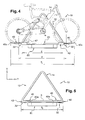
figure 4 est une vue en bout de derrière du porte-vélo(s) dans laquelle les supports sont en position dépliée pour que le porte-vélo(s) puisse recevoir un vélo; - la
figure 5 est une vue similaire à celle de lafigure 4 , dans laquelle les supports sont en position repliée, montrant la réduction de l'encombrement transversal du porte-vélo(s). - Pour la description de l'invention, on adoptera à titre non limitatif les orientations verticale, longitudinale et transversale selon le repère V, L, T indiqué aux figures.
- On adoptera aussi l'orientation d'arrière en avant comme étant la direction longitudinale et de gauche à droite en se reportant à la
figure 1 . - Dans la description qui va suivre, des éléments identiques, similaires ou analogues seront désignés par les mêmes chiffres de référence.
- On a représenté à la
figure 1 un porte-vélo(s) 10 permettant de monter plusieurs vélos, ici deux vélos, à l'arrière d'un véhicule automobile (non représenté), de manière que le cadre de chaque vélo s'étende dans un plan vertical transversal lorsqu'il est en position montée sur le porte-vélo(s). - Le porte-vélo(s) 10 comporte une structure de support 12 qui est fixée au véhicule, et qui est constituée d'un assemblage de tronçons de profilé, et il comporte des moyens pour solidariser chaque vélo à la structure de support 12.
- La structure de support 12 comporte ainsi un arceau vertical avant 14, globalement en forme de trapèze s'étendant dans un plan vertical transversal, qui est constitué de deux montants 16 inclinés par rapport à la verticale et dont les extrémité supérieures 16a sont reliées entre-elles par un tronçon de raccordement transversal 18.
- La structure de support 12 comporte aussi un cadre inférieur 20 de support, qui s'étend horizontalement et vers l'arrière depuis l'arceau vertical 14, et qui comporte deux bras longitudinaux 22 s'étendant chacun vers l'arrière depuis l'extrémité inférieure 16b d'un montant 16 associé et dont les extrémités longitudinales arrière 22a des deux bras longitudinaux 22 sont reliées entre-elles par une traverse arrière 24.
- Enfin, la structure de support 12 comporte des pattes d'ancrage 26 qui s'étendent globalement longitudinalement vers l'avant depuis les bras longitudinaux, en avant par rapport à l'arceau avant 14, et dont les extrémités avant libres 26a coopèrent avec des moyens de fixation complémentaires 28, que l'on a représenté de manière simplifiée par un rectangle, et qui sont portés par un élément de structure du véhicule automobile (non représenté).
- Puisque le porte-vélo(s) 10 s'étend en arrière du véhicule, il masque notamment les feux de signalisation arrière et la plaque minéralogique arrière du véhicule (non représentés).
- Le porte-vélo(s) 10 porte donc une plaque arrière 60 de support, qui est montée sur la traverse arrière 24, et qui porte une plaque minéralogique 62 et des feux de signalisation arrière 64 supplémentaires, remplaçant les éléments masqués, qui sont des éléments de sécurité importants.
- Le porte-vélo(s) 10 comporte aussi un circuit électrique (non représenté) pour relier les feux supplémentaires 64 aux feux associés du véhicule.
- Les moyens de solidarisation de chacun des vélos à la structure de support 12 comportent une barre de verrouillage 30 d'un vélo associé en position montée sur la structure de support 12 et des supports inférieurs 32, dont chacun est associé à une roue d'un vélo .
- Chaque barre de verrouillage 30 s'étend globalement longitudinalement vers l'arrière depuis un montant 16 associé de l'arceau avant 14, son extrémité avant 30a est reliée au montant 16 associé par l'intermédiaire d'une bride 34, et son extrémité arrière 30b porte une pince de serrage d'un tube du cadre du vélo associé.
- Chaque support inférieur 32 est monté sur un bras longitudinal 22, et il délimite un logement creux 38 ouvert vers le haut qui est apte à recevoir une portion inférieure de la roue associée.
- Comme on peut le voir aux
figures 4 et 5 , les supports inférieurs 32 sont écartés transversalement l'un de l'autre d'une distance "d" correspondant sensiblement à la distance entre les roues du vélo. - La longueur d'un vélo, et plus particulièrement d'un vélo pour adulte, est relativement importante par rapport à la largeur du véhicule. La distance "d" est alors elle aussi importante, ce qui implique que l'encombrement transversal du porte-vélo(s) 10 est important.
- Le porte-vélo(s) 10 conforme à l'invention est conçu de manière que l'on peut réduire son encombrement transversal "T" lorsque aucun vélo n'est monté sur le porte-vélo(s) 10.
- Pour cela, la structure de support 12 est conçue de manière que son encombrement transversal "E", qui est délimité par les bras longitudinaux 22, est inférieur à la distance "d" d'écartement des supports inférieurs 32.
- Ainsi, comme on l'a représenté à la
figure 4 , les supports inférieurs 32 s'étendent transversalement au moins en partie à l'extérieur de la structure de support 12, en faisant saillie par rapport aux bras longitudinaux 22 et ils définissent ainsi encombrement transversal "T1" maximum du porte-vélo(s) 10. - Pour permettre la réduction de l'encombrement transversal du porte-vélo(s) 10, et conformément à l'invention, chaque support inférieur 32 comporte une partie 40 qui est mobile par rapport au bras longitudinal 22 associé entre une position déployée dans laquelle la partie mobile 40 fait saillie transversalement vers l'extérieur de la structure de support 12, et une position repliée dans laquelle la partie mobile 40 s'étend transversalement entre les deux bras longitudinaux 22.
- Chacun des supports inférieurs 32 comporte aussi un socle 42 qui est fixé au bras longitudinal 22 associé, et par rapport auquel la partie mobile 40 est mobile.
- Ainsi, comme on peut le voir aux
figures 4 et 5 , lorsque les parties mobiles 40, qui sont situées de chaque coté du porte-vélo(s) 10, sont en position déployée représentée à lafigure 4 , la distance entre leurs extrémités libres 40a définit l'encombrement transversal maximal "T1" du porte-vélo(s). Lorsque ces mêmes parties mobiles 40 sont en position repliée représentée à lafigure 5 , ce sont les socles 42 qui font saillie transversalement vers l'extérieur par rapport au bras longitudinaux 22, et ils définissent ainsi l'encombrement transversal minimal "T2" du porte-vélo(s) 10. - L'encombrement transversal minimal "T2" du porte-vélo(s) 10 dépend donc principalement de la distance entre les bras longitudinaux 22, c'est-à-dire de l'encombrement transversal "E" de la structure de support 12.
- Ainsi, il est possible de définir quel sera l'encombrement transversal minimal "T2" du porte-vélo(s) 10 en déterminant la distance entre les bras longitudinaux 22, par exemple de manière que le porte-vélo 10 puisse être introduit dans le compartiment à bagages du véhicule.
- On a représenté aux
figures 2 et 3 un mode de réalisation préféré d'un support inférieur 32 conforme à l'invention, selon lequel la partie mobile 40 est montée articulée par rapport au socle 42 autour d'un axe A d'orientation principale longitudinale. - Selon ce mode de réalisation, la partie mobile 40 consiste en un arceau en forme de U comportant notamment deux branches parallèles 44, dont les extrémités libres 44a comportent des moyens d'articulation de la partie mobile 40 autour de l'axe longitudinal A qui coopèrent avec des moyens d'articulation complémentaire du socle 42 associé.
- L'articulation de la partie mobile 40 par rapport au socle 42 est ici réalisée par les extrémités libres 44a des branches 44 qui sont recourbées vers l'extérieur de manière qu'elles sont prolongées par un doigt longitudinal 46, coaxial à l'axe longitudinal A d'articulation.
- Chaque doigt 46 est reçu dans un trou complémentaire 48 qui est réalisé dans une patte de support 50 du socle 42. Cette patte de support 50 s'étend vers le haut et dans un plan transversal vertical depuis une face supérieure horizontale 42s du socle 42.
- Le socle 42 est un élément d'orientation principale transversale, il comporte une rainure inférieure longitudinale 52 qui reçoit le bras longitudinal 22 lorsque le socle est en position montée sur le bras longitudinal 22.
- La rainure inférieure 52 est ouverte le long d'une génératrice inférieure pour permettre le montage du socle 42 autour du bras longitudinal 22 par un mouvement vertical descendant du socle 42 par rapport au bras longitudinal 22.
- Le socle 42 comporte aussi des moyens (non représentés) pour sa solidarisation avec le bras longitudinal 22 associé, en pivotement autour de l'axe principal du bras longitudinal 22. Ces moyens de solidarisation consistent par exemple en un doigt vertical qui est reçu dans un trou complémentaire du bras longitudinal 22.
- Comme on l'a dit plus haut, le support 32 délimite un logement creux 38 ouvert vers le haut et dans lequel une partie inférieure de la roue est posée.
- Conformément à l'invention, le logement creux 38 est délimité en partie par le socle 42, et en partie par la partie mobile 40.
- Ainsi, le logement creux 38 est délimité en partie par une gorge supérieure transversale 54 du socle 42, qui débouche dans la face supérieure horizontale 42s du socle et qui débouche dans une face longitudinale verticale d'extrémité externe 42e du socle.
- Cette gorge supérieure 54 est de forme concave globalement complémentaire de la forme d'une roue du vélo.
- La partie mobile 40 délimite aussi le logement creux 38 lorsqu'elle est en position déployée, en coopération avec la gorge supérieure 54 du socle 42.
- A cet effet, lorsque la partie mobile 40 est en position déployée, elle s'étend dans un plan horizontal de manière que les branches 44 s'étendent transversalement vers l'extérieure en prolongeant la gorge supérieure 54.
- Ainsi, la partie mobile 40 et le bord supérieur de la gorge supérieure 54 délimitent l'ouverture supérieure du logement creux 38, et seule la gorge supérieure 54 délimite le fond du logement creux 38.
- Conformément à l'invention, le socle 42 comporte des moyens pour maintenir la partie mobile 40 en position déployée.
- Ces moyens de maintien comportent deux pattes verticales 56 qui s'étendent verticalement vers le haut depuis la face supérieure horizontale 42s du socle 42. Ces pattes verticales 56 sont réparties symétriquement de part et d'autre d'un plan transversal vertical médian du socle 42, et elles sont agencées transversalement à distance de l'axe A longitudinal d'articulation de la partie mobile 40, c'est-à-dire ici à proximité de l'extrémité transversale externe du socle 42.
- Les pattes verticales 56 comportent chacune une rainure transversale 58 réalisée dans une face transversale verticale 56a de la patte 56.
- Lorsque la partie mobile 40 est en position déployée, chaque branche 44 est reçue en partie dans la rainure transversale 58 associée, réalisant de ce fait le blocage en pivotement de la partie mobile 40.
- Pour permettre l'introduction d'une branche 44 dans la rainure 58 associée, les pattes verticales 56 sont déformables élastiquement de manière qu'elles s'effacent lors du mouvement de la partie mobile 40 vers sa position déployée.
- Ici, les rainures 58 sont réalisées dans les faces verticales transversales externes 56a des pattes 56, c'est-à-dire que les pattes 56 sont agencées transversalement entre les branches 44 de la partie mobile 40.
- Selon un autre aspect avantageux de l'invention, comme on peut le voir à la
figure 5 , lorsque les parties mobiles 40 de tous les supports 32 sont en position repliée, elles s'étendent toutes dans un plan horizontal de manière qu'elles définissent conjointement une surface plane S horizontale qui peut par exemple être utilisée pour le chargement d'objets encombrants à l'arrière du véhicule. - Il sera compris que l'invention n'est pas limitée au mode de réalisation qui vient d'être décrit et que les parties mobiles 40 peuvent avoir une autre structure, et qu'elles peuvent par exemple consister chacune en un tronçon de profilé ouvert vers le haut, ou bien elles peuvent être montées coulissantes transversalement par rapport au socle 42 associé.
- Il sera aussi compris que des inversions mécaniques simples peuvent constituer des variantes de réalisation de l'invention. Par exemple, les rainures transversales 58 peuvent être réalisées dans les faces verticales transversales internes des pattes 56, c'est-à-dire que les pattes 56 sont agencées transversalement de part et d'autre de la partie mobile 40.
Claims (10)
- Porte-vélo (10) pour fixer au moins un vélo à l'arrière d'un véhicule automobile, avec son cadre s'étendant selon une orientation globalement verticale transversale, du type comportant une structure de support (12) qui est fixée au véhicule, qui comporte deux bras longitudinaux (22) inférieurs répartis de part et d'autre d'un plan longitudinal vertical médian de la structure de support (12) et qui délimitent l'encombrement transversal (E) général de la structure de support (12),
et des moyens de solidarisation du vélo à la structure de support (12), qui comportent notamment un support (32) inférieur associé à chaque roue du vélo qui est monté sur l'un des bras longitudinaux inférieurs (22) et qui délimite un logement (38) ouvert dans sa partie supérieure et qui reçoit une portion inférieure de la roue associée,
caractérisé en ce que chaque support (32) comporte un socle (42) qui est fixé au bras longitudinal (22) associé et une partie mobile (40) qui s'étend transversalement et qui délimite au moins en partie le logement (38) et qui est monté mobile par rapport au socle (42) entre :- une position déployée dans laquelle le support (32) est apte à recevoir une portion de la roue associée du vélo et dans laquelle ladite partie mobile (40) du support (32) fait saillie transversalement par rapport au bras longitudinal (22) associé vers l'extérieur de la structure de support (12) ;- et une position repliée de rangement, dans laquelle ladite partie mobile (40) du support (32) s'étend transversalement entre les deux bras longitudinaux (22). - Porte-vélo (10) selon la revendication précédente, caractérisé en ce que la partie mobile (40) s'étend dans un plan globalement horizontal lorsque le support (32) est en position déployée et/ou en position repliée.
- Porte-vélo (10) selon l'une quelconque des revendications précédentes, caractérisé en ce que la partie mobile (40) est montée articulée par rapport au socle (42) autour d'un axe (A) d'orientation principale longitudinale.
- Porte-vélo (10) selon l'une quelconque des revendications précédentes, caractérisé en ce que le socle (42) comporte des moyens (56, 58) pour maintenir la partie mobile (40) en position déployée du support (32).
- Porte-vélo (10) selon la revendication précédente, en combinaison avec la revendication 3, caractérisé en ce que les moyens de maintien (56, 58) comportent au moins une patte (56) qui s'étend verticalement vers le haut depuis une face horizontale supérieure (42s) du socle (42), et dont une face verticale transversale (56a) comporte une rainure (58) d'orientation principale transversale qui est apte à recevoir une partie complémentaire (44) de la partie mobile (40) pour son maintien en position.
- Porte-vélo (10) selon la revendication précédente, caractérisé en ce que la patte (56) est disposée transversalement sur le socle (42) à distance de l'axe (A) d'articulation de la partie mobile (40).
- Porte-vélo (10) selon l'une quelconque des revendications précédentes, caractérisé en ce que la partie mobile (40) consiste en un arceau qui est monté articulé par rapport au socle (42) au niveau de ses extrémités (44a).
- Porte-vélo (10) selon la revendication précédente, caractérisé en ce que chaque extrémité (44a) de l'arceau (40) est prolongée par un doigt longitudinal (46) coaxial à l'axe (A) d'articulation de l'arceau (40) par rapport au socle (42) qui est reçu dans un trou complémentaire (48) d'une patte de support (50) qui s'étend verticalement vers le haut depuis la face horizontale supérieure (42s) du socle (42), pour réaliser l'articulation de l'arceau (40) par rapport au socle (42).
- Porte-vélo (10) selon l'une quelconque des revendications précédentes, caractérisé en ce que les supports (32) définissent une surface plane (S) globalement horizontale lorsqu'ils sont en position repliée de rangement.
- Porte-vélo (10) selon l'une quelconque des revendications précédentes, caractérisé en ce que le socle (42) comporte une gorge (54) qui débouche dans la face horizontale supérieure (42s) du socle (42) et dans une face longitudinale verticale d'extrémité externe (42e) du socle (42) et qui délimite en partie le logement (38).
Applications Claiming Priority (2)
| Application Number | Priority Date | Filing Date | Title |
|---|---|---|---|
| FR0450361A FR2866851B1 (fr) | 2004-02-26 | 2004-02-26 | Porte-velo(s) comportant une partie apte a etre repliee transversalement |
| FR0450361 | 2004-02-26 |
Publications (2)
| Publication Number | Publication Date |
|---|---|
| EP1568542A1 EP1568542A1 (fr) | 2005-08-31 |
| EP1568542B1 true EP1568542B1 (fr) | 2009-04-29 |
Family
ID=34746547
Family Applications (1)
| Application Number | Title | Priority Date | Filing Date |
|---|---|---|---|
| EP05300138A Not-in-force EP1568542B1 (fr) | 2004-02-26 | 2005-02-22 | Porte-vélo(s) comportant une partie apte à être repliée transversalement |
Country Status (4)
| Country | Link |
|---|---|
| EP (1) | EP1568542B1 (fr) |
| AT (1) | ATE430064T1 (fr) |
| DE (1) | DE602005014153D1 (fr) |
| FR (1) | FR2866851B1 (fr) |
Families Citing this family (11)
| Publication number | Priority date | Publication date | Assignee | Title |
|---|---|---|---|---|
| US8113398B2 (en) * | 2007-07-06 | 2012-02-14 | Yakima Products, Inc. | Hitch mounted bicycle racks for vehicles |
| DE102008006814A1 (de) * | 2007-07-11 | 2009-01-15 | Westfalia-Automotive Gmbh | Lastenträger für ein Kraftfahrzeug |
| EP2014510B1 (fr) * | 2007-07-11 | 2013-12-18 | WESTFALIA - Automotive GmbH | Support de charge pour un véhicule automobile |
| NZ561811A (en) | 2007-09-21 | 2010-06-25 | Hubco Automotive Ltd | Extendable roof rack |
| DE102011006614B4 (de) | 2011-03-31 | 2018-04-05 | Atera Gmbh | Abstandsstütze für ein Trägersystem für ein Kraftfahrzeug sowie Trägersystem |
| DE102011122285A1 (de) * | 2011-12-23 | 2013-06-27 | Westfalia-Automotive Gmbh | Lastenträger mit an einem Grundträger beweglich gelagerten Lasttragteilen |
| EP2844523B1 (fr) | 2012-04-30 | 2017-04-26 | Yakima Australia Pty Limited | Élément de retenue |
| US9533625B2 (en) | 2014-10-16 | 2017-01-03 | Ford Global Technologies, Llc | Bike rack attachment for vehicle |
| US10040403B2 (en) | 2015-06-09 | 2018-08-07 | Yakima Products, Inc. | Crossbar clamp actuator |
| US10752179B2 (en) | 2016-06-05 | 2020-08-25 | Yakima Products, Inc. | Vehicle hitch mounted bicycle rack |
| USD966171S1 (en) | 2020-11-20 | 2022-10-11 | Yakima Products, Inc. | Bicycle carrier |
Family Cites Families (8)
| Publication number | Priority date | Publication date | Assignee | Title |
|---|---|---|---|---|
| FR2430873A1 (fr) * | 1978-07-10 | 1980-02-08 | Collet Andre | Porte-bicyclette |
| FR2499917A2 (fr) * | 1981-02-13 | 1982-08-20 | Hamel Jacques | Porte-bagages pour vehicules automobiles |
| US4823997A (en) * | 1988-01-05 | 1989-04-25 | P & J Enterprises, Inc. | Cycle carrier |
| DE9110409U1 (fr) * | 1991-08-22 | 1992-03-12 | Lubjuhn, Arnold, 7208 Spaichingen, De | |
| DE4407477A1 (de) * | 1994-03-07 | 1995-09-14 | Apa Kg Bauder Otto | Lasten-Tragevorrichtung zur Montage am Kofferraum-Deckel eines PKW |
| DE4424226A1 (de) * | 1994-07-09 | 1996-01-11 | Apa Kg Bauder Otto | Lasten-Tragevorrichtung zur Montage im Bereich des Kofferraumdeckels oder der Heckklappe eines PKW |
| US6491195B1 (en) | 1999-08-25 | 2002-12-10 | Mclemore John D. | Carrier device |
| DE10144550C2 (de) * | 2001-09-10 | 2003-12-11 | Hs Products Karosseriesysteme | Lastenträger für ein Fahrzeugheck |
-
2004
- 2004-02-26 FR FR0450361A patent/FR2866851B1/fr not_active Expired - Fee Related
-
2005
- 2005-02-22 EP EP05300138A patent/EP1568542B1/fr not_active Not-in-force
- 2005-02-22 AT AT05300138T patent/ATE430064T1/de not_active IP Right Cessation
- 2005-02-22 DE DE602005014153T patent/DE602005014153D1/de active Active
Also Published As
| Publication number | Publication date |
|---|---|
| EP1568542A1 (fr) | 2005-08-31 |
| DE602005014153D1 (de) | 2009-06-10 |
| FR2866851A1 (fr) | 2005-09-02 |
| ATE430064T1 (de) | 2009-05-15 |
| FR2866851B1 (fr) | 2007-05-25 |
Similar Documents
| Publication | Publication Date | Title |
|---|---|---|
| EP1568542B1 (fr) | Porte-vélo(s) comportant une partie apte à être repliée transversalement | |
| EP1136321B1 (fr) | Module de rangement pour véhicule automobile, fermé à l'arrière par une façade formant un élément de carrosserie | |
| EP0323334A1 (fr) | Dispositif pour la fixation de sécurité d'un siège auto enfant sur une banquette arrière de véhicule automobile | |
| FR2829082A1 (fr) | Dispositif formant porte-velos pour le transport d'au moins une bicyclette transversalement a l'arriere d'un vehicule automobile | |
| FR2519927A1 (fr) | Dispositif de coffre a bagages sur petits vehicules | |
| FR2811620A1 (fr) | Siege de vehicule automobile equipe d'un siege d'appoint | |
| FR2516468A1 (fr) | Porte-bagages de type perfectionne particulierement applicable sur les bicyclettes | |
| FR2820382A1 (fr) | Dispositif formant porte-velos pour le transport d'au moins une bicyclette transversalement a l'arriere d'un vehicule automobile | |
| EP3508384B1 (fr) | Porte-velo amovible | |
| FR2467763A1 (fr) | Sacoche destinee a etre fixee sur un cote d'un cycle | |
| FR2531018A1 (fr) | Dispositif de couverture mobile pour camions et autres vehicules | |
| EP1227004B1 (fr) | Dispositif porte-charge à au moins deux positions pour véhicule automobile | |
| FR2706848A3 (en) | Motorcycle of the moped or similar type with retractable elements for protection against rain | |
| FR2893888A3 (fr) | Dispositif cache bagages pour coffre de vehicule automobile et son utilisation. | |
| EP2571705B1 (fr) | Module de toit souple pour vehicule automobile et procede de montage d'un tel module dans le pavillon d'un vehicule automobile | |
| EP0985582A1 (fr) | Dispositif pour fixer un porte-vélo à l'arrière d'une automobile | |
| FR2820381A1 (fr) | Dispositif pour le transport d'au moins un objet transversalement a l'arriere d'un vehicule automobile | |
| EP3888979B1 (fr) | Porte-vélo escamotable | |
| EP3044070A1 (fr) | Poussette pliable adaptable au transport des nouveau-nes | |
| FR2878473A1 (fr) | Pavillon escamotable de vehicule | |
| FR3061880A1 (fr) | Porte-articles de vehicule a barres transversales a basculement en position et escamotables | |
| FR2531021A1 (fr) | Porte-velo profile | |
| FR3073477A1 (fr) | Porte-velos escamotable pour vehicule automobile a compacite amelioree | |
| EP1789309B1 (fr) | Dispositif pour la protection contre les intemperies de l'utilisateur d'un cycle ou analogue | |
| FR2898858A1 (fr) | Vehicule a toit rapporte |
Legal Events
| Date | Code | Title | Description |
|---|---|---|---|
| PUAI | Public reference made under article 153(3) epc to a published international application that has entered the european phase |
Free format text: ORIGINAL CODE: 0009012 |
|
| AK | Designated contracting states |
Kind code of ref document: A1 Designated state(s): AT BE BG CH CY CZ DE DK EE ES FI FR GB GR HU IE IS IT LI LT LU MC NL PL PT RO SE SI SK TR |
|
| AX | Request for extension of the european patent |
Extension state: AL BA HR LV MK YU |
|
| 17P | Request for examination filed |
Effective date: 20060217 |
|
| AKX | Designation fees paid |
Designated state(s): AT BE BG CH CY CZ DE DK EE ES FI FR GB GR HU IE IS IT LI LT LU MC NL PL PT RO SE SI SK TR |
|
| 17Q | First examination report despatched |
Effective date: 20060626 |
|
| GRAP | Despatch of communication of intention to grant a patent |
Free format text: ORIGINAL CODE: EPIDOSNIGR1 |
|
| GRAS | Grant fee paid |
Free format text: ORIGINAL CODE: EPIDOSNIGR3 |
|
| GRAA | (expected) grant |
Free format text: ORIGINAL CODE: 0009210 |
|
| AK | Designated contracting states |
Kind code of ref document: B1 Designated state(s): AT BE BG CH CY CZ DE DK EE ES FI FR GB GR HU IE IS IT LI LT LU MC NL PL PT RO SE SI SK TR |
|
| REG | Reference to a national code |
Ref country code: GB Ref legal event code: FG4D Free format text: NOT ENGLISH |
|
| REG | Reference to a national code |
Ref country code: CH Ref legal event code: EP |
|
| REF | Corresponds to: |
Ref document number: 602005014153 Country of ref document: DE Date of ref document: 20090610 Kind code of ref document: P |
|
| REG | Reference to a national code |
Ref country code: IE Ref legal event code: FG4D |
|
| NLV1 | Nl: lapsed or annulled due to failure to fulfill the requirements of art. 29p and 29m of the patents act | ||
| PG25 | Lapsed in a contracting state [announced via postgrant information from national office to epo] |
Ref country code: LT Free format text: LAPSE BECAUSE OF FAILURE TO SUBMIT A TRANSLATION OF THE DESCRIPTION OR TO PAY THE FEE WITHIN THE PRESCRIBED TIME-LIMIT Effective date: 20090429 Ref country code: FI Free format text: LAPSE BECAUSE OF FAILURE TO SUBMIT A TRANSLATION OF THE DESCRIPTION OR TO PAY THE FEE WITHIN THE PRESCRIBED TIME-LIMIT Effective date: 20090429 Ref country code: ES Free format text: LAPSE BECAUSE OF FAILURE TO SUBMIT A TRANSLATION OF THE DESCRIPTION OR TO PAY THE FEE WITHIN THE PRESCRIBED TIME-LIMIT Effective date: 20090809 Ref country code: AT Free format text: LAPSE BECAUSE OF FAILURE TO SUBMIT A TRANSLATION OF THE DESCRIPTION OR TO PAY THE FEE WITHIN THE PRESCRIBED TIME-LIMIT Effective date: 20090429 Ref country code: PT Free format text: LAPSE BECAUSE OF FAILURE TO SUBMIT A TRANSLATION OF THE DESCRIPTION OR TO PAY THE FEE WITHIN THE PRESCRIBED TIME-LIMIT Effective date: 20090829 |
|
| PG25 | Lapsed in a contracting state [announced via postgrant information from national office to epo] |
Ref country code: NL Free format text: LAPSE BECAUSE OF FAILURE TO SUBMIT A TRANSLATION OF THE DESCRIPTION OR TO PAY THE FEE WITHIN THE PRESCRIBED TIME-LIMIT Effective date: 20090429 Ref country code: IS Free format text: LAPSE BECAUSE OF FAILURE TO SUBMIT A TRANSLATION OF THE DESCRIPTION OR TO PAY THE FEE WITHIN THE PRESCRIBED TIME-LIMIT Effective date: 20090829 Ref country code: SI Free format text: LAPSE BECAUSE OF FAILURE TO SUBMIT A TRANSLATION OF THE DESCRIPTION OR TO PAY THE FEE WITHIN THE PRESCRIBED TIME-LIMIT Effective date: 20090429 Ref country code: PL Free format text: LAPSE BECAUSE OF FAILURE TO SUBMIT A TRANSLATION OF THE DESCRIPTION OR TO PAY THE FEE WITHIN THE PRESCRIBED TIME-LIMIT Effective date: 20090429 Ref country code: SE Free format text: LAPSE BECAUSE OF FAILURE TO SUBMIT A TRANSLATION OF THE DESCRIPTION OR TO PAY THE FEE WITHIN THE PRESCRIBED TIME-LIMIT Effective date: 20090729 |
|
| REG | Reference to a national code |
Ref country code: IE Ref legal event code: FD4D |
|
| PG25 | Lapsed in a contracting state [announced via postgrant information from national office to epo] |
Ref country code: IE Free format text: LAPSE BECAUSE OF FAILURE TO SUBMIT A TRANSLATION OF THE DESCRIPTION OR TO PAY THE FEE WITHIN THE PRESCRIBED TIME-LIMIT Effective date: 20090429 Ref country code: CZ Free format text: LAPSE BECAUSE OF FAILURE TO SUBMIT A TRANSLATION OF THE DESCRIPTION OR TO PAY THE FEE WITHIN THE PRESCRIBED TIME-LIMIT Effective date: 20090429 Ref country code: RO Free format text: LAPSE BECAUSE OF FAILURE TO SUBMIT A TRANSLATION OF THE DESCRIPTION OR TO PAY THE FEE WITHIN THE PRESCRIBED TIME-LIMIT Effective date: 20090429 Ref country code: DK Free format text: LAPSE BECAUSE OF FAILURE TO SUBMIT A TRANSLATION OF THE DESCRIPTION OR TO PAY THE FEE WITHIN THE PRESCRIBED TIME-LIMIT Effective date: 20090429 Ref country code: EE Free format text: LAPSE BECAUSE OF FAILURE TO SUBMIT A TRANSLATION OF THE DESCRIPTION OR TO PAY THE FEE WITHIN THE PRESCRIBED TIME-LIMIT Effective date: 20090429 |
|
| PG25 | Lapsed in a contracting state [announced via postgrant information from national office to epo] |
Ref country code: SK Free format text: LAPSE BECAUSE OF FAILURE TO SUBMIT A TRANSLATION OF THE DESCRIPTION OR TO PAY THE FEE WITHIN THE PRESCRIBED TIME-LIMIT Effective date: 20090429 |
|
| PLBE | No opposition filed within time limit |
Free format text: ORIGINAL CODE: 0009261 |
|
| STAA | Information on the status of an ep patent application or granted ep patent |
Free format text: STATUS: NO OPPOSITION FILED WITHIN TIME LIMIT |
|
| PG25 | Lapsed in a contracting state [announced via postgrant information from national office to epo] |
Ref country code: BG Free format text: LAPSE BECAUSE OF FAILURE TO SUBMIT A TRANSLATION OF THE DESCRIPTION OR TO PAY THE FEE WITHIN THE PRESCRIBED TIME-LIMIT Effective date: 20090729 |
|
| 26N | No opposition filed |
Effective date: 20100201 |
|
| BERE | Be: lapsed |
Owner name: RENAULT Effective date: 20100228 |
|
| REG | Reference to a national code |
Ref country code: CH Ref legal event code: PL |
|
| PG25 | Lapsed in a contracting state [announced via postgrant information from national office to epo] |
Ref country code: MC Free format text: LAPSE BECAUSE OF NON-PAYMENT OF DUE FEES Effective date: 20100301 Ref country code: LI Free format text: LAPSE BECAUSE OF NON-PAYMENT OF DUE FEES Effective date: 20100228 Ref country code: GR Free format text: LAPSE BECAUSE OF FAILURE TO SUBMIT A TRANSLATION OF THE DESCRIPTION OR TO PAY THE FEE WITHIN THE PRESCRIBED TIME-LIMIT Effective date: 20090730 Ref country code: CH Free format text: LAPSE BECAUSE OF NON-PAYMENT OF DUE FEES Effective date: 20100228 |
|
| PG25 | Lapsed in a contracting state [announced via postgrant information from national office to epo] |
Ref country code: BE Free format text: LAPSE BECAUSE OF NON-PAYMENT OF DUE FEES Effective date: 20100228 |
|
| PG25 | Lapsed in a contracting state [announced via postgrant information from national office to epo] |
Ref country code: IT Free format text: LAPSE BECAUSE OF FAILURE TO SUBMIT A TRANSLATION OF THE DESCRIPTION OR TO PAY THE FEE WITHIN THE PRESCRIBED TIME-LIMIT Effective date: 20090429 |
|
| PG25 | Lapsed in a contracting state [announced via postgrant information from national office to epo] |
Ref country code: CY Free format text: LAPSE BECAUSE OF FAILURE TO SUBMIT A TRANSLATION OF THE DESCRIPTION OR TO PAY THE FEE WITHIN THE PRESCRIBED TIME-LIMIT Effective date: 20090429 |
|
| PG25 | Lapsed in a contracting state [announced via postgrant information from national office to epo] |
Ref country code: HU Free format text: LAPSE BECAUSE OF FAILURE TO SUBMIT A TRANSLATION OF THE DESCRIPTION OR TO PAY THE FEE WITHIN THE PRESCRIBED TIME-LIMIT Effective date: 20091030 Ref country code: LU Free format text: LAPSE BECAUSE OF NON-PAYMENT OF DUE FEES Effective date: 20100222 |
|
| PG25 | Lapsed in a contracting state [announced via postgrant information from national office to epo] |
Ref country code: TR Free format text: LAPSE BECAUSE OF FAILURE TO SUBMIT A TRANSLATION OF THE DESCRIPTION OR TO PAY THE FEE WITHIN THE PRESCRIBED TIME-LIMIT Effective date: 20090429 |
|
| REG | Reference to a national code |
Ref country code: FR Ref legal event code: PLFP Year of fee payment: 11 |
|
| REG | Reference to a national code |
Ref country code: FR Ref legal event code: PLFP Year of fee payment: 12 |
|
| REG | Reference to a national code |
Ref country code: FR Ref legal event code: PLFP Year of fee payment: 13 |
|
| REG | Reference to a national code |
Ref country code: FR Ref legal event code: PLFP Year of fee payment: 14 |
|
| PGFP | Annual fee paid to national office [announced via postgrant information from national office to epo] |
Ref country code: GB Payment date: 20220223 Year of fee payment: 18 Ref country code: DE Payment date: 20220217 Year of fee payment: 18 |
|
| PGFP | Annual fee paid to national office [announced via postgrant information from national office to epo] |
Ref country code: FR Payment date: 20220216 Year of fee payment: 18 |
|
| REG | Reference to a national code |
Ref country code: DE Ref legal event code: R119 Ref document number: 602005014153 Country of ref document: DE |
|
| GBPC | Gb: european patent ceased through non-payment of renewal fee |
Effective date: 20230222 |
|
| PG25 | Lapsed in a contracting state [announced via postgrant information from national office to epo] |
Ref country code: GB Free format text: LAPSE BECAUSE OF NON-PAYMENT OF DUE FEES Effective date: 20230222 |
|
| PG25 | Lapsed in a contracting state [announced via postgrant information from national office to epo] |
Ref country code: GB Free format text: LAPSE BECAUSE OF NON-PAYMENT OF DUE FEES Effective date: 20230222 Ref country code: FR Free format text: LAPSE BECAUSE OF NON-PAYMENT OF DUE FEES Effective date: 20230228 Ref country code: DE Free format text: LAPSE BECAUSE OF NON-PAYMENT OF DUE FEES Effective date: 20230901 |