EP1568542B1 - Fahradhalter mit einem Querfaltteil - Google Patents
Fahradhalter mit einem Querfaltteil Download PDFInfo
- Publication number
- EP1568542B1 EP1568542B1 EP05300138A EP05300138A EP1568542B1 EP 1568542 B1 EP1568542 B1 EP 1568542B1 EP 05300138 A EP05300138 A EP 05300138A EP 05300138 A EP05300138 A EP 05300138A EP 1568542 B1 EP1568542 B1 EP 1568542B1
- Authority
- EP
- European Patent Office
- Prior art keywords
- bicycle
- mounting part
- bracket
- longitudinal
- bicycle carrier
- Prior art date
- Legal status (The legal status is an assumption and is not a legal conclusion. Google has not performed a legal analysis and makes no representation as to the accuracy of the status listed.)
- Expired - Lifetime
Links
- 230000000295 complement effect Effects 0.000 claims description 8
- 230000000630 rising effect Effects 0.000 claims 2
- 230000013011 mating Effects 0.000 claims 1
- 239000000969 carrier Substances 0.000 description 2
- 238000004873 anchoring Methods 0.000 description 1
- 238000012423 maintenance Methods 0.000 description 1
Images


Classifications
-
- B—PERFORMING OPERATIONS; TRANSPORTING
- B60—VEHICLES IN GENERAL
- B60R—VEHICLES, VEHICLE FITTINGS, OR VEHICLE PARTS, NOT OTHERWISE PROVIDED FOR
- B60R9/00—Supplementary fittings on vehicle exterior for carrying loads, e.g. luggage, sports gear or the like
- B60R9/08—Supplementary fittings on vehicle exterior for carrying loads, e.g. luggage, sports gear or the like specially adapted for sports gear
- B60R9/10—Supplementary fittings on vehicle exterior for carrying loads, e.g. luggage, sports gear or the like specially adapted for sports gear for cycles
-
- B—PERFORMING OPERATIONS; TRANSPORTING
- B60—VEHICLES IN GENERAL
- B60R—VEHICLES, VEHICLE FITTINGS, OR VEHICLE PARTS, NOT OTHERWISE PROVIDED FOR
- B60R9/00—Supplementary fittings on vehicle exterior for carrying loads, e.g. luggage, sports gear or the like
- B60R9/06—Supplementary fittings on vehicle exterior for carrying loads, e.g. luggage, sports gear or the like at vehicle front or rear
Definitions
- the invention provides a bicycle carrier (s) for transporting at least one bike to the rear of a vehicle, which can be folded transversely when not in use.
- the invention more particularly proposes a bicycle carrier (s) for fixing at least one bicycle to the rear of a motor vehicle, with its frame extending in a generally vertical transverse orientation, of the type comprising a support structure which is attached to the vehicle, which comprises two lower longitudinal arms distributed on either side of a median vertical longitudinal plane of the support structure and which delimit the general transverse bulk of the support structure, and means for securing the bicycle to the support structure, which comprise in particular a lower support associated with each wheel of the bicycle which is mounted on one of the lower longitudinal arms and which delimits an open housing in its upper part and which receives a lower portion of the associated wheel .
- bike carrier that are mounted on the roof of the vehicle
- bike carriers that the we ride to the rear of the vehicle.
- Bicycle carriers (s) that are mounted at the rear of a motor vehicle mainly comprise a support structure which consists of an assembly of section sections, and means for attaching one or more bicycles to the structure of the vehicle. support.
- the support structure comprises a first set of profile sections which extend in a horizontal plane, and which carry supports which each receive a portion of a wheel of a bicycle.
- the support structure also comprises a second set of section sections which extend in a transverse vertical plane situated at the rear of the vehicle, and which bear means for connecting the frame of each bike to the support structure.
- the support structure thus occupies a particularly large volume because its dimensions must be adapted to the dimensions of the bicycles that it must support.
- the bike carrier (s) is generally detached from the rear of the vehicle to be stored either in a garage or in the rear luggage compartment of the vehicle.
- the elements of the support structure always retain the same transverse size which is generally equal to the length of the bicycle.
- the document DE-A-4407477 discloses a bicycle carrier (s) for which each lower support is pivotally mounted relative to the longitudinal arm on which it is mounted.
- the bicycle carrier (s) has two additional longitudinal arms to lock the supports in the deployed position and in the folded position.
- the invention aims to provide a bicycle carrier (s) which comprises a support structure which it is possible to reduce at least its transverse size, to allow storage of the bike carrier (s) at least inside the rear luggage compartment of the vehicle.
- the invention provides a bicycle carrier (s) of the type described above, characterized in that at least a portion of each support is movable relative to the longitudinal arm associated, between an extended position in which the support is adapted to receive a portion of the associated wheel of the bicycle and wherein said movable portion of the support projects transversely relative to the associated longitudinal arm towards the outside of the support structure and a folded storage position, wherein said movable portion of the support extends transversely between the two longitudinal arms.
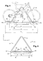
- FIG. 1 a bicycle carrier (s) 10 for mounting several bicycles, here two bicycles, at the rear of a motor vehicle (not shown), so that the frame of each bicycle extends in a transverse vertical plane when it is in the mounted position on the bike carrier (s).
- the carrier (s) 10 comprises a support structure 12 which is fixed to the vehicle, and which consists of an assembly of section sections, and it comprises means for securing each bicycle to the support structure 12.
- the support structure 12 thus comprises a front vertical arch 14, generally trapezoid-shaped extending in a transverse vertical plane, which consists of two uprights 16 inclined relative to the vertical and whose upper ends 16a are interconnected. they have a transverse connection section 18.
- the support structure 12 also comprises a lower support frame 20, which extends horizontally and rearwardly from the vertical hoop 14, and which comprises two longitudinal arms 22 each extending rearwardly from the end lower 16b of an associated upright 16 and whose rear longitudinal ends 22a of the two longitudinal arms 22 are interconnected by a rear crossmember 24.
- the support structure 12 comprises anchoring tabs 26 which extend generally longitudinally forwards from the longitudinal arms, forward with respect to the front bow 14, and whose free front ends 26a cooperate with complementary fastening means 28, which is shown in a simplified manner by a rectangle, and which are carried by a structural element of the motor vehicle (not shown).
- the bike carrier (s) 10 extends behind the vehicle, it masks including the rear traffic lights and the rear license plate of the vehicle (not shown).
- the carrier (s) 10 therefore carries a rear support plate 60, which is mounted on the rear crossmember 24, and which carries a number plate 62 and additional rear signal lights 64, replacing the masked elements, which are important security features.
- the carrier (s) 10 also includes an electrical circuit (not shown) for connecting the additional lights 64 to the associated lights of the vehicle.
- the securing means of each of the bikes to the support structure 12 comprise a locking bar 30 of an associated bicycle in the mounted position on the support structure 12 and lower supports 32, each of which is associated with a wheel of a bike .
- Each locking bar 30 extends generally longitudinally rearwards from an associated upright 16 of the front bow 14, its front end 30a is connected to the associated upright 16 via a strap 34, and its rear end 30b carries a clamp of a tube of the associated bicycle frame.
- Each lower support 32 is mounted on a longitudinal arm 22, and it defines a hollow housing 38 open upwards which is adapted to receive a lower portion of the associated wheel.
- the lower supports 32 are spaced transversely from one another by a distance "d" substantially corresponding to the distance between the wheels of the bicycle.
- the length of a bicycle, and more particularly an adult bicycle, is relatively large compared to the width of the vehicle.
- the distance "d" is then also important, which implies that the transverse size of the carrier (s) 10 is important.
- the carrier (s) 10 according to the invention is designed so that one can reduce its transverse size "T" when no bike is mounted on the carrier (s) 10.
- the support structure 12 is designed so that its transverse size "E", which is delimited by the longitudinal arms 22, is smaller than the spacing distance "d" of the lower supports 32.
- the lower supports 32 extend transversely at least partly outside the support structure 12, projecting from the longitudinal arms 22 and thus define the maximum transverse dimension "T1" of the bicycle carrier (s) 10.
- each lower support 32 has a portion 40 which is movable relative to the longitudinal arm 22 associated between a deployed position in which the movable portion 40 protrudes transversely outwardly of the support structure 12, and a folded position in which the movable portion 40 extends transversely between the two longitudinal arms 22.
- Each of the lower supports 32 also comprises a base 42 which is fixed to the associated longitudinal arm 22, and relative to which the mobile part 40 is movable.
- the minimum transverse space requirement "T2" of the carrier (s) 10 therefore depends mainly on the distance between the longitudinal arms 22, that is to say the transverse space "E" of the support structure 12.
- Figures 2 and 3 a preferred embodiment of a lower support 32 according to the invention, wherein the movable portion 40 is articulated relative to the base 42 about an axis A longitudinal main orientation.
- the mobile part 40 consists of a U-shaped arch comprising in particular two parallel branches 44 whose free ends 44a comprise means of articulation of the mobile part 40 about the longitudinal axis A which cooperate with complementary articulation means of the base 42 associated.
- the articulation of the movable portion 40 with respect to the base 42 is here made by the free ends 44a of the branches 44 which are bent outwards so that they are extended by a longitudinal finger 46, coaxial with the longitudinal axis A hinge.
- Each finger 46 is received in a complementary hole 48 which is made in a support lug 50 of the base 42.
- This support lug 50 extends upwards and in a vertical transverse plane from a horizontal upper face 42s of the base 42.
- the base 42 is a main transverse orientation element, it comprises a longitudinal lower groove 52 which receives the longitudinal arm 22 when the base is in position mounted on the longitudinal arm 22.
- the lower groove 52 is open along a lower generatrix to allow mounting of the base 42 around the longitudinal arm 22 by a vertical downward movement of the base 42 relative to the longitudinal arm 22.
- the base 42 also comprises means (not shown) for securing it with the associated longitudinal arm 22, pivoting about the main axis of the longitudinal arm 22.
- These securing means consist for example of a vertical finger which is received in a complementary hole of the longitudinal arm 22.
- the support 32 delimits a hollow housing 38 open upwards and in which a lower portion of the wheel is placed.
- the hollow housing 38 is delimited in part by the base 42, and partly by the movable part 40.
- the hollow housing 38 is delimited in part by a transverse upper groove 54 of the base 42, which opens into the horizontal upper face 42s of the base and which opens into a longitudinal vertical end external end 42e of the base.
- This upper groove 54 is of concave shape globally complementary to the shape of a bicycle wheel.
- the mobile part 40 also delimits the hollow housing 38 when it is in the deployed position, in cooperation with the upper groove 54 of the base 42.
- the mobile part 40 when the mobile part 40 is in the deployed position, it extends in a horizontal plane so that the branches 44 extend transversely towards the outside by extending the upper groove 54.
- the mobile part 40 and the upper edge of the upper groove 54 define the upper opening of the hollow housing 38, and only the upper groove 54 defines the bottom of the hollow housing 38.
- the base 42 comprises means for holding the mobile part 40 in the deployed position.
- These holding means comprise two vertical legs 56 which extend vertically upwards from the horizontal upper face 42s of the base 42. These vertical legs 56 are distributed symmetrically on either side of a plane transverse vertical transverse base 42, and they are arranged transversely at a distance from the longitudinal axis A articulation of the movable portion 40, that is to say here in the vicinity of the outer transverse end of the base 42.
- the vertical tabs 56 each comprise a transverse groove 58 made in a vertical transverse face 56a of the tab 56.
- each branch 44 is partially received in the associated transverse groove 58, thereby achieving pivotal locking of the movable portion 40.
- the vertical legs 56 are elastically deformable so that they fade during movement of the movable portion 40 to its deployed position.
- the grooves 58 are made in the external transverse vertical faces 56a of the tabs 56, that is to say that the tabs 56 are arranged transversely between the branches 44 of the mobile part 40.
- the invention is not limited to the embodiment which has just been described and that the movable parts 40 may have another structure, and that they may for example each consist of an open profile section towards the top, or they can be mounted sliding transversely relative to the base 42 associated.
- transverse grooves 58 may be made in the internal transverse vertical faces of the tabs 56, that is to say that the tabs 56 are arranged transversely on either side of the movable part 40.
Landscapes
- Engineering & Computer Science (AREA)
- Mechanical Engineering (AREA)
- Motorcycle And Bicycle Frame (AREA)
- Absorbent Articles And Supports Therefor (AREA)
- Carriages For Children, Sleds, And Other Hand-Operated Vehicles (AREA)
- Steering Devices For Bicycles And Motorcycles (AREA)
Claims (10)
- Fahrradhalter (10) zur Befestigung mindestens eines Fahrrads am hinteren Teil eines Kraftfahrzeugs, wobei sich sein Rahmen in einer allgemein vertikalen Querausrichtung erstreckt, jener Art, die eine Stützstruktur (12) aufweist, die an dem Fahrzeug befestigt ist und die zwei untere Längsarme (22) aufweist, die auf beiden Seiten einer vertikalen, mittleren Längsebene der Stützstruktur (12) verteilt sind und die die allgemeinen Querabmessungen (E) der Stützstruktur (12) begrenzen,
und Mittel zur festen Verbindung des Fahrrads mit der Stützstruktur (12), die insbesondere einen unteren Träger (32) aufweisen, der jedem Fahrradrad zugeordnet ist, das an einem der unteren Längsarme (22) angebracht ist und eine Aufnahme (38) begrenzt, die in ihrem oberen Teil offen ist und einen unteren Teil des zugehörigen Rads aufnimmt,
dadurch gekennzeichnet, dass jeder Träger (32) einen Fuß (42), der an dem zugehörigen Längsarm (22) befestigt ist, und einen beweglichen Teil (40) aufweist, der sich in Querrichtung erstreckt, zumindest teilweise die Aufnahme (38) begrenzt und bezüglich des Fußes (42) zwischen:- einer entfalteten Position, in der der Träger (32) einen Teil des zugehörigen Rads des Fahrrads aufnehmen kann und in der der bewegliche Teil (40) des Trägers (32) in Querrichtung bezüglich des zugehörigen Längsarms (22) von der Stützstruktur (12) nach außen vorragt;- und einer eingeklappten Verstauposition, in der sich der bewegliche Teil (40) des Trägers (32) in Querrichtung zwischen den beiden Längsarmen (22) erstreckt, beweglich angebracht ist. - Fahrradhalter (10) nach dem vorhergehenden Anspruch, dadurch gekennzeichnet, dass sich der bewegliche Teil (40) in einer allgemein horizontalen Ebene erstreckt, wenn sich der Träger (32) in einer entfalteten und/oder eingeklappten Position befindet.
- Fahrradhalter (10) nach einem der vorhergehenden Ansprüche, dadurch gekennzeichnet, dass der bewegliche Teil (40) bezüglich des Fußes (42) gelenkig um eine Achse (A) mit einer längs verlaufenden Hauptausrichtung angebracht ist.
- Fahrradhalter (10) nach einem der vorhergehenden Ansprüche, dadurch gekennzeichnet, dass der Fuß (42) Mittel (56, 58) zum Halten des beweglichen Teils (40) in der entfalteten Position des Trägers (32) aufweist.
- Fahrradhalter (10) nach dem vorhergehenden Anspruch in Kombination mit Anspruch 3, dadurch gekennzeichnet, dass die Haltemittel (56, 58) mindestens einen Ansatz (56) aufweisen, der sich von einer horizontalen Oberseite (42s) des Fußes (42) vertikal nach oben erstreckt und von dem eine vertikale Querfläche (56a) eine in erster Linie in Querrichtung ausgerichtete Nut (58) aufweist, die einen komplementären Teil (44) des beweglichen Teils (40) aufnehmen kann, um ihn in Position zu halten.
- Fahrradhalter (10) nach dem vorhergehenden Anspruch, dadurch gekennzeichnet, dass der Ansatz (56) quer auf dem Fuß (42) in einem Abstand von der Gelenkachse (A) des beweglichen Teils (40) angeordnet ist.
- Fahrradhalter (10) nach einem der vorhergehenden Ansprüche, dadurch gekennzeichnet, dass der bewegliche Teil (40) aus einem Bügel besteht, der an seinen Enden (44a) gelenkig bezüglich des Fußes (42) angelenkt ist.
- Fahrradhalter (10) nach dem vorhergehenden Anspruch, dadurch gekennzeichnet, dass jedes Ende (44a) des Bügels (40) durch einen zur Gelenkachse (A) des Bügels (40) bezüglich des Fußes (42) koaxialen Längsfinger (46) verlängert ist, der in einem komplementären Loch (48) eines Stützansatzes (50), der sich von der horizontalen Oberseite (42s) des Fußes (42) vertikal nach oben erstreckt, aufgenommen wird, um die Anlenkung des Bogens (40) bezüglich des Fußes (42) zu realisieren.
- Fahrradhalter (10) nach einem der vorhergehenden Ansprüche, dadurch gekennzeichnet, dass die Träger (32) eine allgemein horizontal ebene Fläche (S) definieren, wenn sie sich in einer eingeklappten Verstauposition befinden.
- Fahrradhalter (10) nach einem der vorhergehenden Ansprüche, dadurch gekennzeichnet, dass der Fuß (42) einen Kanal (54) aufweist, der in der horizontalen Oberseite (42s) des Fußes (42) und in einer vertikalen Längsfläche des äußeren Endes (42e) des Fußes (42) mündet und die Aufnahme (38) teilweise begrenzt.
Applications Claiming Priority (2)
| Application Number | Priority Date | Filing Date | Title |
|---|---|---|---|
| FR0450361A FR2866851B1 (fr) | 2004-02-26 | 2004-02-26 | Porte-velo(s) comportant une partie apte a etre repliee transversalement |
| FR0450361 | 2004-02-26 |
Publications (2)
| Publication Number | Publication Date |
|---|---|
| EP1568542A1 EP1568542A1 (de) | 2005-08-31 |
| EP1568542B1 true EP1568542B1 (de) | 2009-04-29 |
Family
ID=34746547
Family Applications (1)
| Application Number | Title | Priority Date | Filing Date |
|---|---|---|---|
| EP05300138A Expired - Lifetime EP1568542B1 (de) | 2004-02-26 | 2005-02-22 | Fahradhalter mit einem Querfaltteil |
Country Status (4)
| Country | Link |
|---|---|
| EP (1) | EP1568542B1 (de) |
| AT (1) | ATE430064T1 (de) |
| DE (1) | DE602005014153D1 (de) |
| FR (1) | FR2866851B1 (de) |
Families Citing this family (13)
| Publication number | Priority date | Publication date | Assignee | Title |
|---|---|---|---|---|
| US8235267B2 (en) * | 2007-07-06 | 2012-08-07 | Yakima Products, Inc. | Hitch-mountable bicycle carrier |
| DE102008006814A1 (de) * | 2007-07-11 | 2009-01-15 | Westfalia-Automotive Gmbh | Lastenträger für ein Kraftfahrzeug |
| EP2014510B1 (de) * | 2007-07-11 | 2013-12-18 | WESTFALIA - Automotive GmbH | Lastenträger für ein Kraftfahrzeug |
| NZ561811A (en) | 2007-09-21 | 2010-06-25 | Hubco Automotive Ltd | Extendable roof rack |
| DE102011006614B4 (de) | 2011-03-31 | 2018-04-05 | Atera Gmbh | Abstandsstütze für ein Trägersystem für ein Kraftfahrzeug sowie Trägersystem |
| DE102011122285A1 (de) * | 2011-12-23 | 2013-06-27 | Westfalia-Automotive Gmbh | Lastenträger mit an einem Grundträger beweglich gelagerten Lasttragteilen |
| AU2013255540A1 (en) | 2012-04-30 | 2014-12-18 | Yakima Australia Pty Limited | Retention dock |
| US9533625B2 (en) | 2014-10-16 | 2017-01-03 | Ford Global Technologies, Llc | Bike rack attachment for vehicle |
| US10040403B2 (en) | 2015-06-09 | 2018-08-07 | Yakima Products, Inc. | Crossbar clamp actuator |
| WO2017214017A1 (en) | 2016-06-05 | 2017-12-14 | Yakima Products, Inc. | Vehicle hitch mounted bicycle rack |
| USD966171S1 (en) | 2020-11-20 | 2022-10-11 | Yakima Products, Inc. | Bicycle carrier |
| USD1054963S1 (en) | 2023-05-30 | 2024-12-24 | Yakima Products, Inc. | Bicycle carrier |
| USD1110927S1 (en) | 2024-05-17 | 2026-02-03 | Yakima Products, Inc. | Bicycle carrier |
Family Cites Families (8)
| Publication number | Priority date | Publication date | Assignee | Title |
|---|---|---|---|---|
| FR2430873A1 (fr) * | 1978-07-10 | 1980-02-08 | Collet Andre | Porte-bicyclette |
| FR2499917A2 (fr) * | 1981-02-13 | 1982-08-20 | Hamel Jacques | Porte-bagages pour vehicules automobiles |
| US4823997A (en) * | 1988-01-05 | 1989-04-25 | P & J Enterprises, Inc. | Cycle carrier |
| DE9110409U1 (de) * | 1991-08-22 | 1992-03-12 | Lubjuhn, Arnold, 7208 Spaichingen | Fahrradhalter zum Transport von Fahrrädern durch Kraftfahrzeuge und Karavane |
| DE4407477A1 (de) * | 1994-03-07 | 1995-09-14 | Apa Kg Bauder Otto | Lasten-Tragevorrichtung zur Montage am Kofferraum-Deckel eines PKW |
| DE4424226A1 (de) * | 1994-07-09 | 1996-01-11 | Apa Kg Bauder Otto | Lasten-Tragevorrichtung zur Montage im Bereich des Kofferraumdeckels oder der Heckklappe eines PKW |
| US6491195B1 (en) | 1999-08-25 | 2002-12-10 | Mclemore John D. | Carrier device |
| DE10144550C2 (de) * | 2001-09-10 | 2003-12-11 | Hs Products Karosseriesysteme | Lastenträger für ein Fahrzeugheck |
-
2004
- 2004-02-26 FR FR0450361A patent/FR2866851B1/fr not_active Expired - Fee Related
-
2005
- 2005-02-22 DE DE602005014153T patent/DE602005014153D1/de not_active Expired - Lifetime
- 2005-02-22 AT AT05300138T patent/ATE430064T1/de not_active IP Right Cessation
- 2005-02-22 EP EP05300138A patent/EP1568542B1/de not_active Expired - Lifetime
Also Published As
| Publication number | Publication date |
|---|---|
| ATE430064T1 (de) | 2009-05-15 |
| FR2866851A1 (fr) | 2005-09-02 |
| FR2866851B1 (fr) | 2007-05-25 |
| DE602005014153D1 (de) | 2009-06-10 |
| EP1568542A1 (de) | 2005-08-31 |
Similar Documents
| Publication | Publication Date | Title |
|---|---|---|
| EP1568542B1 (de) | Fahradhalter mit einem Querfaltteil | |
| EP1136321B1 (de) | Kraftfahrzeug- Ablage- Modul, am Ende geschlossen durch einem Fahrzeugkarosserieformkörper | |
| EP0323334A1 (de) | Vorrichtung zur Sicherungsbefestigung eines Kinderautositzes auf der hinteren Sitzbank eines Kraftfahrzeuges | |
| FR2811620A1 (fr) | Siege de vehicule automobile equipe d'un siege d'appoint | |
| FR2516468A1 (fr) | Porte-bagages de type perfectionne particulierement applicable sur les bicyclettes | |
| FR2829082A1 (fr) | Dispositif formant porte-velos pour le transport d'au moins une bicyclette transversalement a l'arriere d'un vehicule automobile | |
| FR2668435A1 (fr) | Porte-velo de voiture destine a etre fixe a l'arriere d'un vehicule pour assurer le transport d'une bicyclette. | |
| FR2820382A1 (fr) | Dispositif formant porte-velos pour le transport d'au moins une bicyclette transversalement a l'arriere d'un vehicule automobile | |
| EP0041889A1 (de) | Gepäckbrücke für Kraftfahrzeuge | |
| FR2467763A1 (fr) | Sacoche destinee a etre fixee sur un cote d'un cycle | |
| FR2531018A1 (fr) | Dispositif de couverture mobile pour camions et autres vehicules | |
| EP1227004B1 (de) | Lasttragevorrichtung mit mindestens zwei Positionen für Kraftfahrzeuge | |
| EP3508384B1 (de) | Abnehmbarer fahrradträger | |
| EP3888979B1 (de) | Versenkbarer fahrradträger | |
| FR2706848A3 (en) | Motorcycle of the moped or similar type with retractable elements for protection against rain | |
| EP0985582A1 (de) | Vorrichtung zum Befestigen eines Fahrradträgers am Heck eines Kraftfahrzeugs | |
| EP2571705B1 (de) | Faltdachmodul für kraftfahrzeug und montageverfahren für ein solches modul im kraftfahrzeugdach | |
| FR2820381A1 (fr) | Dispositif pour le transport d'au moins un objet transversalement a l'arriere d'un vehicule automobile | |
| FR2878473A1 (fr) | Pavillon escamotable de vehicule | |
| FR2531021A1 (fr) | Porte-velo profile | |
| WO2015036395A1 (fr) | Poussette pliable adaptable au transport des nouveau-nes | |
| FR2893888A3 (fr) | Dispositif cache bagages pour coffre de vehicule automobile et son utilisation. | |
| EP1789309B1 (de) | Vorrichtung zum schutz von benutzern von fahrrädern o. ä. gegen das wetter | |
| FR3061880A1 (fr) | Porte-articles de vehicule a barres transversales a basculement en position et escamotables | |
| FR3141118A1 (fr) | Support de charge à l’intérieur d’un véhicule automobile. |
Legal Events
| Date | Code | Title | Description |
|---|---|---|---|
| PUAI | Public reference made under article 153(3) epc to a published international application that has entered the european phase |
Free format text: ORIGINAL CODE: 0009012 |
|
| AK | Designated contracting states |
Kind code of ref document: A1 Designated state(s): AT BE BG CH CY CZ DE DK EE ES FI FR GB GR HU IE IS IT LI LT LU MC NL PL PT RO SE SI SK TR |
|
| AX | Request for extension of the european patent |
Extension state: AL BA HR LV MK YU |
|
| 17P | Request for examination filed |
Effective date: 20060217 |
|
| AKX | Designation fees paid |
Designated state(s): AT BE BG CH CY CZ DE DK EE ES FI FR GB GR HU IE IS IT LI LT LU MC NL PL PT RO SE SI SK TR |
|
| 17Q | First examination report despatched |
Effective date: 20060626 |
|
| GRAP | Despatch of communication of intention to grant a patent |
Free format text: ORIGINAL CODE: EPIDOSNIGR1 |
|
| GRAS | Grant fee paid |
Free format text: ORIGINAL CODE: EPIDOSNIGR3 |
|
| GRAA | (expected) grant |
Free format text: ORIGINAL CODE: 0009210 |
|
| AK | Designated contracting states |
Kind code of ref document: B1 Designated state(s): AT BE BG CH CY CZ DE DK EE ES FI FR GB GR HU IE IS IT LI LT LU MC NL PL PT RO SE SI SK TR |
|
| REG | Reference to a national code |
Ref country code: GB Ref legal event code: FG4D Free format text: NOT ENGLISH |
|
| REG | Reference to a national code |
Ref country code: CH Ref legal event code: EP |
|
| REF | Corresponds to: |
Ref document number: 602005014153 Country of ref document: DE Date of ref document: 20090610 Kind code of ref document: P |
|
| REG | Reference to a national code |
Ref country code: IE Ref legal event code: FG4D |
|
| NLV1 | Nl: lapsed or annulled due to failure to fulfill the requirements of art. 29p and 29m of the patents act | ||
| PG25 | Lapsed in a contracting state [announced via postgrant information from national office to epo] |
Ref country code: LT Free format text: LAPSE BECAUSE OF FAILURE TO SUBMIT A TRANSLATION OF THE DESCRIPTION OR TO PAY THE FEE WITHIN THE PRESCRIBED TIME-LIMIT Effective date: 20090429 Ref country code: FI Free format text: LAPSE BECAUSE OF FAILURE TO SUBMIT A TRANSLATION OF THE DESCRIPTION OR TO PAY THE FEE WITHIN THE PRESCRIBED TIME-LIMIT Effective date: 20090429 Ref country code: ES Free format text: LAPSE BECAUSE OF FAILURE TO SUBMIT A TRANSLATION OF THE DESCRIPTION OR TO PAY THE FEE WITHIN THE PRESCRIBED TIME-LIMIT Effective date: 20090809 Ref country code: AT Free format text: LAPSE BECAUSE OF FAILURE TO SUBMIT A TRANSLATION OF THE DESCRIPTION OR TO PAY THE FEE WITHIN THE PRESCRIBED TIME-LIMIT Effective date: 20090429 Ref country code: PT Free format text: LAPSE BECAUSE OF FAILURE TO SUBMIT A TRANSLATION OF THE DESCRIPTION OR TO PAY THE FEE WITHIN THE PRESCRIBED TIME-LIMIT Effective date: 20090829 |
|
| PG25 | Lapsed in a contracting state [announced via postgrant information from national office to epo] |
Ref country code: NL Free format text: LAPSE BECAUSE OF FAILURE TO SUBMIT A TRANSLATION OF THE DESCRIPTION OR TO PAY THE FEE WITHIN THE PRESCRIBED TIME-LIMIT Effective date: 20090429 Ref country code: IS Free format text: LAPSE BECAUSE OF FAILURE TO SUBMIT A TRANSLATION OF THE DESCRIPTION OR TO PAY THE FEE WITHIN THE PRESCRIBED TIME-LIMIT Effective date: 20090829 Ref country code: SI Free format text: LAPSE BECAUSE OF FAILURE TO SUBMIT A TRANSLATION OF THE DESCRIPTION OR TO PAY THE FEE WITHIN THE PRESCRIBED TIME-LIMIT Effective date: 20090429 Ref country code: PL Free format text: LAPSE BECAUSE OF FAILURE TO SUBMIT A TRANSLATION OF THE DESCRIPTION OR TO PAY THE FEE WITHIN THE PRESCRIBED TIME-LIMIT Effective date: 20090429 Ref country code: SE Free format text: LAPSE BECAUSE OF FAILURE TO SUBMIT A TRANSLATION OF THE DESCRIPTION OR TO PAY THE FEE WITHIN THE PRESCRIBED TIME-LIMIT Effective date: 20090729 |
|
| REG | Reference to a national code |
Ref country code: IE Ref legal event code: FD4D |
|
| PG25 | Lapsed in a contracting state [announced via postgrant information from national office to epo] |
Ref country code: IE Free format text: LAPSE BECAUSE OF FAILURE TO SUBMIT A TRANSLATION OF THE DESCRIPTION OR TO PAY THE FEE WITHIN THE PRESCRIBED TIME-LIMIT Effective date: 20090429 Ref country code: CZ Free format text: LAPSE BECAUSE OF FAILURE TO SUBMIT A TRANSLATION OF THE DESCRIPTION OR TO PAY THE FEE WITHIN THE PRESCRIBED TIME-LIMIT Effective date: 20090429 Ref country code: RO Free format text: LAPSE BECAUSE OF FAILURE TO SUBMIT A TRANSLATION OF THE DESCRIPTION OR TO PAY THE FEE WITHIN THE PRESCRIBED TIME-LIMIT Effective date: 20090429 Ref country code: DK Free format text: LAPSE BECAUSE OF FAILURE TO SUBMIT A TRANSLATION OF THE DESCRIPTION OR TO PAY THE FEE WITHIN THE PRESCRIBED TIME-LIMIT Effective date: 20090429 Ref country code: EE Free format text: LAPSE BECAUSE OF FAILURE TO SUBMIT A TRANSLATION OF THE DESCRIPTION OR TO PAY THE FEE WITHIN THE PRESCRIBED TIME-LIMIT Effective date: 20090429 |
|
| PG25 | Lapsed in a contracting state [announced via postgrant information from national office to epo] |
Ref country code: SK Free format text: LAPSE BECAUSE OF FAILURE TO SUBMIT A TRANSLATION OF THE DESCRIPTION OR TO PAY THE FEE WITHIN THE PRESCRIBED TIME-LIMIT Effective date: 20090429 |
|
| PLBE | No opposition filed within time limit |
Free format text: ORIGINAL CODE: 0009261 |
|
| STAA | Information on the status of an ep patent application or granted ep patent |
Free format text: STATUS: NO OPPOSITION FILED WITHIN TIME LIMIT |
|
| PG25 | Lapsed in a contracting state [announced via postgrant information from national office to epo] |
Ref country code: BG Free format text: LAPSE BECAUSE OF FAILURE TO SUBMIT A TRANSLATION OF THE DESCRIPTION OR TO PAY THE FEE WITHIN THE PRESCRIBED TIME-LIMIT Effective date: 20090729 |
|
| 26N | No opposition filed |
Effective date: 20100201 |
|
| BERE | Be: lapsed |
Owner name: RENAULT Effective date: 20100228 |
|
| REG | Reference to a national code |
Ref country code: CH Ref legal event code: PL |
|
| PG25 | Lapsed in a contracting state [announced via postgrant information from national office to epo] |
Ref country code: MC Free format text: LAPSE BECAUSE OF NON-PAYMENT OF DUE FEES Effective date: 20100301 Ref country code: LI Free format text: LAPSE BECAUSE OF NON-PAYMENT OF DUE FEES Effective date: 20100228 Ref country code: GR Free format text: LAPSE BECAUSE OF FAILURE TO SUBMIT A TRANSLATION OF THE DESCRIPTION OR TO PAY THE FEE WITHIN THE PRESCRIBED TIME-LIMIT Effective date: 20090730 Ref country code: CH Free format text: LAPSE BECAUSE OF NON-PAYMENT OF DUE FEES Effective date: 20100228 |
|
| PG25 | Lapsed in a contracting state [announced via postgrant information from national office to epo] |
Ref country code: BE Free format text: LAPSE BECAUSE OF NON-PAYMENT OF DUE FEES Effective date: 20100228 |
|
| PG25 | Lapsed in a contracting state [announced via postgrant information from national office to epo] |
Ref country code: IT Free format text: LAPSE BECAUSE OF FAILURE TO SUBMIT A TRANSLATION OF THE DESCRIPTION OR TO PAY THE FEE WITHIN THE PRESCRIBED TIME-LIMIT Effective date: 20090429 |
|
| PG25 | Lapsed in a contracting state [announced via postgrant information from national office to epo] |
Ref country code: CY Free format text: LAPSE BECAUSE OF FAILURE TO SUBMIT A TRANSLATION OF THE DESCRIPTION OR TO PAY THE FEE WITHIN THE PRESCRIBED TIME-LIMIT Effective date: 20090429 |
|
| PG25 | Lapsed in a contracting state [announced via postgrant information from national office to epo] |
Ref country code: HU Free format text: LAPSE BECAUSE OF FAILURE TO SUBMIT A TRANSLATION OF THE DESCRIPTION OR TO PAY THE FEE WITHIN THE PRESCRIBED TIME-LIMIT Effective date: 20091030 Ref country code: LU Free format text: LAPSE BECAUSE OF NON-PAYMENT OF DUE FEES Effective date: 20100222 |
|
| PG25 | Lapsed in a contracting state [announced via postgrant information from national office to epo] |
Ref country code: TR Free format text: LAPSE BECAUSE OF FAILURE TO SUBMIT A TRANSLATION OF THE DESCRIPTION OR TO PAY THE FEE WITHIN THE PRESCRIBED TIME-LIMIT Effective date: 20090429 |
|
| REG | Reference to a national code |
Ref country code: FR Ref legal event code: PLFP Year of fee payment: 11 |
|
| REG | Reference to a national code |
Ref country code: FR Ref legal event code: PLFP Year of fee payment: 12 |
|
| REG | Reference to a national code |
Ref country code: FR Ref legal event code: PLFP Year of fee payment: 13 |
|
| REG | Reference to a national code |
Ref country code: FR Ref legal event code: PLFP Year of fee payment: 14 |
|
| PGFP | Annual fee paid to national office [announced via postgrant information from national office to epo] |
Ref country code: GB Payment date: 20220223 Year of fee payment: 18 Ref country code: DE Payment date: 20220217 Year of fee payment: 18 |
|
| PGFP | Annual fee paid to national office [announced via postgrant information from national office to epo] |
Ref country code: FR Payment date: 20220216 Year of fee payment: 18 |
|
| REG | Reference to a national code |
Ref country code: DE Ref legal event code: R119 Ref document number: 602005014153 Country of ref document: DE |
|
| GBPC | Gb: european patent ceased through non-payment of renewal fee |
Effective date: 20230222 |
|
| PG25 | Lapsed in a contracting state [announced via postgrant information from national office to epo] |
Ref country code: GB Free format text: LAPSE BECAUSE OF NON-PAYMENT OF DUE FEES Effective date: 20230222 |
|
| PG25 | Lapsed in a contracting state [announced via postgrant information from national office to epo] |
Ref country code: GB Free format text: LAPSE BECAUSE OF NON-PAYMENT OF DUE FEES Effective date: 20230222 Ref country code: FR Free format text: LAPSE BECAUSE OF NON-PAYMENT OF DUE FEES Effective date: 20230228 Ref country code: DE Free format text: LAPSE BECAUSE OF NON-PAYMENT OF DUE FEES Effective date: 20230901 |