EP1568438B1 - Werkzeugmaschine - Google Patents
Werkzeugmaschine Download PDFInfo
- Publication number
- EP1568438B1 EP1568438B1 EP05101186A EP05101186A EP1568438B1 EP 1568438 B1 EP1568438 B1 EP 1568438B1 EP 05101186 A EP05101186 A EP 05101186A EP 05101186 A EP05101186 A EP 05101186A EP 1568438 B1 EP1568438 B1 EP 1568438B1
- Authority
- EP
- European Patent Office
- Prior art keywords
- tool
- laser beam
- end portion
- workpiece
- side end
- Prior art date
- Legal status (The legal status is an assumption and is not a legal conclusion. Google has not performed a legal analysis and makes no representation as to the accuracy of the status listed.)
- Expired - Lifetime
Links
Images

Classifications
-
- B—PERFORMING OPERATIONS; TRANSPORTING
- B23—MACHINE TOOLS; METAL-WORKING NOT OTHERWISE PROVIDED FOR
- B23K—SOLDERING OR UNSOLDERING; WELDING; CLADDING OR PLATING BY SOLDERING OR WELDING; CUTTING BY APPLYING HEAT LOCALLY, e.g. FLAME CUTTING; WORKING BY LASER BEAM
- B23K26/00—Working by laser beam, e.g. welding, cutting or boring
- B23K26/02—Positioning or observing the workpiece, e.g. with respect to the point of impact; Aligning, aiming or focusing the laser beam
- B23K26/06—Shaping the laser beam, e.g. by masks or multi-focusing
- B23K26/0604—Shaping the laser beam, e.g. by masks or multi-focusing by a combination of beams
-
- B—PERFORMING OPERATIONS; TRANSPORTING
- B23—MACHINE TOOLS; METAL-WORKING NOT OTHERWISE PROVIDED FOR
- B23K—SOLDERING OR UNSOLDERING; WELDING; CLADDING OR PLATING BY SOLDERING OR WELDING; CUTTING BY APPLYING HEAT LOCALLY, e.g. FLAME CUTTING; WORKING BY LASER BEAM
- B23K26/00—Working by laser beam, e.g. welding, cutting or boring
- B23K26/0093—Working by laser beam, e.g. welding, cutting or boring combined with mechanical machining or metal-working covered by other subclasses than B23K
-
- B—PERFORMING OPERATIONS; TRANSPORTING
- B23—MACHINE TOOLS; METAL-WORKING NOT OTHERWISE PROVIDED FOR
- B23K—SOLDERING OR UNSOLDERING; WELDING; CLADDING OR PLATING BY SOLDERING OR WELDING; CUTTING BY APPLYING HEAT LOCALLY, e.g. FLAME CUTTING; WORKING BY LASER BEAM
- B23K26/00—Working by laser beam, e.g. welding, cutting or boring
- B23K26/08—Devices involving relative movement between laser beam and workpiece
- B23K26/0823—Devices involving rotation of the workpiece
-
- B—PERFORMING OPERATIONS; TRANSPORTING
- B23—MACHINE TOOLS; METAL-WORKING NOT OTHERWISE PROVIDED FOR
- B23K—SOLDERING OR UNSOLDERING; WELDING; CLADDING OR PLATING BY SOLDERING OR WELDING; CUTTING BY APPLYING HEAT LOCALLY, e.g. FLAME CUTTING; WORKING BY LASER BEAM
- B23K26/00—Working by laser beam, e.g. welding, cutting or boring
- B23K26/14—Working by laser beam, e.g. welding, cutting or boring using a fluid stream, e.g. a jet of gas, in conjunction with the laser beam; Nozzles therefor
- B23K26/142—Working by laser beam, e.g. welding, cutting or boring using a fluid stream, e.g. a jet of gas, in conjunction with the laser beam; Nozzles therefor for the removal of by-products
-
- B—PERFORMING OPERATIONS; TRANSPORTING
- B23—MACHINE TOOLS; METAL-WORKING NOT OTHERWISE PROVIDED FOR
- B23K—SOLDERING OR UNSOLDERING; WELDING; CLADDING OR PLATING BY SOLDERING OR WELDING; CUTTING BY APPLYING HEAT LOCALLY, e.g. FLAME CUTTING; WORKING BY LASER BEAM
- B23K26/00—Working by laser beam, e.g. welding, cutting or boring
- B23K26/14—Working by laser beam, e.g. welding, cutting or boring using a fluid stream, e.g. a jet of gas, in conjunction with the laser beam; Nozzles therefor
- B23K26/1462—Nozzles; Features related to nozzles
- B23K26/1482—Detachable nozzles, e.g. exchangeable or provided with breakaway lines
-
- B—PERFORMING OPERATIONS; TRANSPORTING
- B23—MACHINE TOOLS; METAL-WORKING NOT OTHERWISE PROVIDED FOR
- B23K—SOLDERING OR UNSOLDERING; WELDING; CLADDING OR PLATING BY SOLDERING OR WELDING; CUTTING BY APPLYING HEAT LOCALLY, e.g. FLAME CUTTING; WORKING BY LASER BEAM
- B23K26/00—Working by laser beam, e.g. welding, cutting or boring
- B23K26/70—Auxiliary operations or equipment
- B23K26/702—Auxiliary equipment
-
- C—CHEMISTRY; METALLURGY
- C21—METALLURGY OF IRON
- C21D—MODIFYING THE PHYSICAL STRUCTURE OF FERROUS METALS; GENERAL DEVICES FOR HEAT TREATMENT OF FERROUS OR NON-FERROUS METALS OR ALLOYS; MAKING METAL MALLEABLE, e.g. BY DECARBURISATION OR TEMPERING
- C21D1/00—General methods or devices for heat treatment, e.g. annealing, hardening, quenching or tempering
- C21D1/06—Surface hardening
- C21D1/09—Surface hardening by direct application of electrical or wave energy; by particle radiation
-
- C—CHEMISTRY; METALLURGY
- C21—METALLURGY OF IRON
- C21D—MODIFYING THE PHYSICAL STRUCTURE OF FERROUS METALS; GENERAL DEVICES FOR HEAT TREATMENT OF FERROUS OR NON-FERROUS METALS OR ALLOYS; MAKING METAL MALLEABLE, e.g. BY DECARBURISATION OR TEMPERING
- C21D2261/00—Machining or cutting being involved
-
- Y—GENERAL TAGGING OF NEW TECHNOLOGICAL DEVELOPMENTS; GENERAL TAGGING OF CROSS-SECTIONAL TECHNOLOGIES SPANNING OVER SEVERAL SECTIONS OF THE IPC; TECHNICAL SUBJECTS COVERED BY FORMER USPC CROSS-REFERENCE ART COLLECTIONS [XRACs] AND DIGESTS
- Y10—TECHNICAL SUBJECTS COVERED BY FORMER USPC
- Y10T—TECHNICAL SUBJECTS COVERED BY FORMER US CLASSIFICATION
- Y10T483/00—Tool changing
- Y10T483/17—Tool changing including machine tool or component
Definitions
- the invention relates to a machine tool having both tool rest for movably supporting at least a tool and a laser beam generating means.
- a conventional machine tool can change a tool, and with such a machine tool, various kinds of machining is executed (see a Japanese patent application, Publication No. H11 (1999) - 77467) .
- JP 61 164 738 A discloses a machine tool capable of laser beam machining. The purpose is to perform complicated laser beam machining easily and quickly by accommodating a laser beam machining head in a tool magazine of a machining center and providing a laser beam projecting means to irradiate the laser beam emitted by a laser beam generator.
- DE 101 26 165 A1 discloses a method for hardening the surface of a workpiece using lasers. However, only one laser beam is used for the hardening making the process inefficient.
- the invention relates to a machine tool according to claim 1.
- hardening with laser beam can be performed with the machine tool in addition to cutting machining. Then, it is not necessary to locate a hardening unit in addition to a machine tool, thereby preventing increase of space for location. Besides, it is not necessary to move a workpiece from the machine tool to the laser beam hardening unit, thereby shortening time for operation and simplifying the operation itself.
- Another aspect of the invention is the machine tool, wherein said tool rest is rotationally moved around a rotationally moving axis, and said laser beam generating means is located at a surface of said tool rest almost perpendicular to said rotationally moving axis.
- the laser beam generating means it is sufficient to locate the laser beam generating means at an existent empty space (that is, the surface of the tool rest almost perpendicular to the rotationally moving axis), and a new space for location is not necessary to be secured, thereby preventing the big sized machine tool.
- Another aspect of the invention according to claim 1 relates to a machine tool, wherein said laser beam generating means has a semiconducting laser beam source for emitting laser beam, and a beam guiding portion for transmitting said laser beam emitted.
- the laser beam generating means can be made smaller since the semiconducting laser beam source is used, thereby actualizing installation of the laser beam generating means on the tool rest.
- Another aspect of the invention according to claim 1 relates to a machine tool, wherein said semiconducting laser beam source has a plurality of openings for emission, for emitting said laser beam, and said beam guide portion is comprised of a first beam guide portion which is a bundle of a plurality of optical fibers, said optical fiber being located so as to receive said laser beam from each said opening for emission, and a second beam guide portion located so as to pass through said laser beam from said first beam guide portion.
- a plurality of optical fibers collect laser beam emitted from each opening for emission, thereby raising output of the laser beam.
- Another aspect of the invention according to claim 1 relates to a machine tool, wherein said second beam guide portion is a hollow path formed at an inside of a predetermined member, and an inner face of said hollow path is processed so as to reflect, and said laser beam passes through said hollow path, being reflected by said inner face.
- the second beam guide portion can be formed by mechanical machining, thereby improving an accuracy of the position of the optical path of laser beam. Besides, an efficiency of cooling can be also improved when using a material having a superior heat conductivity for the predetermined member.
- Another aspect of the invention according to claim 1 relates to a machine tool, wherein at least one of said first and second beam guide portions has a tapered beam path portion having a gradually reduced cross sectional area, and power density of said laser beam from said semiconducting laser beam source is enhanced during passing said laser beam through said tapered beam path portion.
- the power density can be raised, thereby smoothly performing hardening with laser beam.
- Another aspect of the invention is the machine tool, wherein said tool rest has at least one tool installation portion for supporting a tool for cutting machining and supporting a tool for emitting laser beam in place of said tool for cutting machining, and said beam guide portion is located, extending from a portion near said semiconducting laser beam source to a portion near said tool installation portion, having a tool side end portion near said tool installation portion, and said laser beam supplied from said semiconducting laser beam source radiates said workpiece when said tool for emitting laser beam connects with said tool side end portion of said beam guide portion, while said tool being supported by said tool installation portion.
- the tool for emitting laser beam can be detached from the tool rest if not used, thereby preventing attachment of foreign objects to the tool for emitting laser beam.
- a single tool installation portion can support both the tools for cutting machining and for emitting laser beam, thereby making the unit compact.
- Another aspect of the invention is the machine tool, wherein said workpiece holding means can rotate held said workpiece, and an automatic tool changer is located at a position being capable of facing said tool installation portion so as to attach and detach said tool for cutting machining and said tool for emitting laser beam to and from said tool installation portion, and cutting machining and a hardening can be executed on rotating said workpiece by changing said tool with said automatic tool changer.
- the tool can be easily attached and detached.
- Another aspect of the invention is the machine tool, wherein a shutter means for opening and closing said tool side end portion is provided, and said shutter means opens said tool side end portion when contacting said tool for emitting laser beam with said tool side end portion and closes said tool side end portion when detaching said tool for emitting laser beam from said tool side end portion in order to restrict attachment of foreign objects to said tool side end portion.
- attachment of foreign obj ects to the end portion (the end portion on the tool side) of the beam guide portion can be restricted, thereby avoiding power down of laser beam due to the presence of foreign objects in the beam guide portion.
- shutter means is a member movable to a closed position for closing said tool side end portion and an opened position for opening said tool side end portion.
- the structure of the shutter means can be made simple.
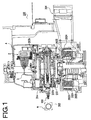
- Fig.1 is a sectional view showing a structure of a machine tool according to the invention
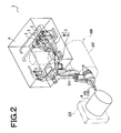
- Fig.2 is a perspective view showing an appearance of the machine tool according to the invention
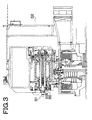
- Fig.3 is a sectional view showing the machine tool when installing a tool for cutting machining 201
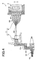
- Fig.4 is a sectional view showing structures of a laser beam generating means and a tool for radiating laser beam
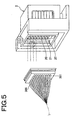
- Fig.5 is a perspective view showing an appearance of a structure of the laser beam generating means
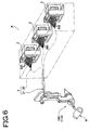
- Fig.6 is a perspective view showing appearances of structures of the laser beam generating means and the tool for radiating laser beam
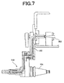
- Fig.7 is a partial sectional view showing a structure of an installation portion of the tool for radiating laser beam
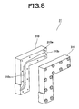
- Fig.8 is an exploded perspective view showing a structure of a second beam guide portion
- Fig.9 is a view showing a structure of a tapered beam path portion
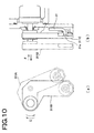
- Fig.10 is a view showing a closing mechanism in an end of an opening
- a machine tool 200 according to the invention as shown in Figs. 1 and 2 has a workpiece holding means 203 for holding a workpiece W and a tool rest 202 for supporting a tool 201 as shown in Fig.3.
- the workpiece holding means 203 can hold the stationary workpiece W, and move and rotate the workpiece W.
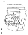
- the workpiece holding means for rotating the workpiece W are a chuck 203A as shown in Fig.14, a tail stock (not shown) and the like.
- the tool rest 202 supports at least one tool, movably between a waiting position and a machining position (a position where the workpiece W is machined).
- the tool rest 202 is rotatably moved around a rotationally moving axis 202a.
- the tool rest 202 has at least one tool installation portion 2026, and the tool is attachably and detachably supported by the tool installation portion 2026.
- a reference number 2021 of Fig.1 denotes an axial portion
- a reference number 2022 denotes a movable portion rotatably supported by the axial portion 2021, for rotating around the rotationally moving axis 202a together with the tool installation portion 2026.
- a case 2023 stores the axial portion 2021 and the movable portion 2022.
- a core 2024 is supported on a side of the case 2023, and a coil 2025 is wound on the core 2024.
- a plurality of magnets 2027 are located at a position facing the core 2024 at an outer peripheral face of the movable portion 2022 in the peripheral direction of the movable portion 2022.
- the cooling unit 204 is effective for cooling such heat. With the cooling unit 204, thermal expansion of the core 2024 and the coil 2025 can be reduced, thereby properly keeping a gap between the core 2024 and the magnet 2027.
- a laser beam generating means A for generating laser beam of Fig.1 is located at the tool rest 202, and hardening is executed on the workpiece W held by the workpiece holding means 203 with laser beam generated from the laser beam generating means A.
- hardening can be executed with the machine tool in addition to cutting machining, thereby preventing increase of a space for locating a laser beam hardening unit.
- such hardening is executed, while rotating the workpinece W by the workpiece holding means 203.
- the laser beam generating means A is located at a surface 202b of the tool rest 202, almost perpendicular to the rotationally moving axis 202a if the tool rest 202 is rotationally moved around the rotationally moving axis 202a. In such a case, it is sufficient to locate the laser beam generating means A in an existent empty space (that is, the surface of the tool rest almost perpendicular to the rotationally moving axis). Then, it is not necessary to secure a new location space, thereby avoiding a large sized machine tool.
- the laser beam generating means A is comprised of a semiconducting laser beam source 2 for emitting laser beam and a beam guide portion 3 for transmitting emitted laser beam, as detailedly shown in Fig.4.
- the laser beam generating means A can be made smaller, and can be located at the tool rest 202.
- the semiconducting laser beam source 2 has a plurality of emitters 20 which are openings for emitting laser beam, as detailedly shown in Fig.5.
- the source 2 may be "an array type" wherein the emitters 20 are arranged in a row or "a stack type” wherein a plurality of the arrays are stacked. Only one or more (as shown in Fig.6) semiconducting laser beam sources 2 may be used. In Fig.6, three sources 2 are shown, but the number may be two, four or more.
- Such kind of the semiconducting laser beam source 2 is a semiconducting laser beam stacked array "Light Stack" made by Coherent Inc. of the U.S.A., for instance.
- the beam guide portion 3 has a first beam guide portion 30 comprised of a bundle of a plurality of optical fibers 300, and a second beam guide portion 31 located so as to pass laser beam from the first beam guide portion 30, as shown in Fig.4.
- the optical fiber 300 is located such that an end thereof faces the emitter 20 in order to receive laser beam from each emitter 20 (see Fig.5), and laser beam emitted from each emitter 20 is transmitted. In such a case, output of laser beam can be raised since a plurality of optical fibers 300 collects laser beam emitted from each emitter 20.
- the end portion of each optical fiber 300 in a state of being embedded in a resin 301 is located, facing each emitter 20.
- a microlens 21 located between the end portion of the optical fiber 300 and the emitter 20 collects laser beam from the emitter 20 on an end face of the optical fiber 300.
- a sheet shaped microlens is attached to the semiconducting laser beam source 2 with an adhesive or by soldering.
- the other ends of the optical fibers 300 may be bundled.
- the number of the optical fibers 300 is the same as one of the emitters 20.
- the second beam guide portion 31 may be a beam guiding body (see a reference number 312 of Fig.7) having an outer peripheral face processed so as to reflect, and laser beam passes through the beam guiding body, being reflected by the outer peripheral face.
- the second beam guide portion 31 may be a hollow path (see reference numbers 310b, 310c) formed inside a predetermined member 310 ("the path forming member" hereinafter) as shown in Fig.8, and the inner face of the path is processed so as to reflect, and laser beam passes through the hollow path, being reflected by the inner face.
- the path forming member 310 is made of metal, such as aluminium.
- Amethodof forming the hollow path is that the path forming member is formed so as to divide into a plurality of the members 310, and a groove 310b is formed at a mating face 310a, as shown in Fig.8. Preferably, mirror finish, lapping or metal coating is carried out on the portion of the groove 310b.
- the second beam guide portion 31 is comprised of the beam guiding body, the position of the optical path of laser beam can be easily adjusted only by changing the position of the beam guiding body. If the second beam guide portion 31 is comprised of the hollow path, the second beam guide portion can be formed by mechanical machining, and an accuracy of the position of the optical path of laser beam can be improved. If a material having superior heat conductivity is used for the predetermined material, an efficiency of cooling can be also improved.
- At least one of the first and second beam guide portions 30, 31 has a tapered beam path portion having a cross-section (area of a transverse section) gradually reducing along a direction of advancing laser beam, and the laser beam from the semiconducting laser beam source 2 is improved in its power density in a process of passing through the tapered beam path portion.
- the tapered beam path portion may be a bundle structure comprised of a plurality of optical fibers, having a cross-section gradually reducing.
- a structure is applied to the optical fibers 30 comprising the first beam guide portion 30 (see a reference number 302 of Fig.7).
- the number of the emitters 20 is 1425
- the number of the optical fibers 300 is necessary to be also 1425.
- Fig.9(a) shows one fiber 300 before processing to be tapered
- a reference number 300a is a clad
- a reference number 300b is a core
- Fig.9(b) shows the fiber 300 after machining so as to be tapered
- Fig.9(c) shows a bundle structure comprised of the fibers after tapering machining.
- a reference number 303 denotes a clad newly coated.
- Such bundle structure may be used for the second beam guide portion 31, not for the first beam guide portion 30.
- a tapered fiber (see Japanese patent applications, Publication numbers are 2003-100123. 2003-75658 and 2002-289016) may be used for the tapered beam path portion.
- a tapered hollow path may be formed inside the predetermined member 310.
- the tool installation portion 2026 supports the tool for cutting machining (see the reference number 201 of Fig. 3), or supports a tool for emitting laser beam (reference numbers 100, 110 of Figs.1, 2, 4, 6 or 7) in place of the tool for cutting machining. Then, the tools for emitting laser beam 100, 110 can be detached from the tool rest 202 when not using, thereby preventing foreign objects from adhering to the tools for emitting laser beam 100, 110. Besides, the unit becomes compact since a single tool installation portion 2026 can support both the tool for cutting machining 201 and the tools for emitting laser beam 100, 110.
- the beam guide portion 3 is located, extending from a portion near the semiconducting laser beam source 2 and to a portion near the tool installation portion 2026, and has a tool side end portion 31a near the tool installation portion 2026, and the tool for emitting laser beam 100 or 110 connects with the tool side end portion 31a, being supported by the tool installation portion 2026, so that laser beam supplied from the semiconducting laser beam source 2 is radiated on the workpiece W.
- a shutter means for opening and closing the tool side end portion 31a is provided so as to open the end portion 31a when contacting the tools for emitting leaser beam 100, 110 with the tool side end portion 31a, and so as to close the tool side end portion 31a when detaching the tools for emitting laser beam 100, 110 from the end portion 31a in order to save attachment of foreign objects to the end portion.
- a shutter means 311 may be provided so as to be moved to a closed position 311c for closing the tool side end portion 31a and an opened position 311A for opening the end portion 31a, as shown in Fig.10. That is, the shutter means 311 may be rotationally movable in a direction of a reference number E, and may enter or come out in an axial direction of the rotational axis as shown with a reference number F.
- the end portion 31a of the beam guide portion 3 is opened so as to connect with the tools for emitting laser beam 100, 110 in a state of 311A, and the end portion 31a is closed in a state of 311C after moving from 311B so as not to enter foreign objects into the end portion 31a or adhere foreign objects to the end portion 31a.
- the structure is simple if the shutter means is one shown in Fig.10.
- the machine tool may be one shown in Fig.14. That is, the workpiece holding means 203A rotates the held workpiece W, and a tool rest 202A has a tool installation portion 2026A. And, an automatic tool changer (not shown) may be located at a position facing the tool installation portion 2026A (such as a position corresponding to a mechanical origin of the tool rest 202A which is provided on a side of the direction Y of Fig.14, and the automatic tool changer attaches and detaches the tool for cutting machining and the tools for emitting laser beam to and from the tool installation portion 2026A.
- a stock portion (ATC tool magazine) 210 having a plurality of the tools for cutting machining and for emitting laser beam is provided, and the tool stocked by the stock portion 210 is installed in the tool installation portion 2026Aby the automatic tool changer.
- the stock portion 210 has such a structure that a tool to be newly installed according to machining program is transferred to a position facing the automatic tool changer.
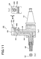
- Fig.11(a) is a partial sectional view showing a structure of the tool for radiating laser beam
- Fig.11(b) is a side view showing a structure of a torch portion 103
- Fig.11(c) is a side view showing a structure of a shutter means 105
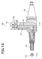
- Fig.12(a) is a partial sectional view showing another structure of the tool for radiating laser beam
- Fig.12(b) is a side view showing a structure of a torch portion 113.
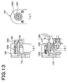
- Fig.13 is a view showing a structure of the shutter means for properly closing an end portion of a beam guide path (a path of laser beam) wherein (a) is a sectional view showing a state of a closed position, (b) is a sectional view showing a state of an opened position, and (c) is a side view showing a state of the closed position.
- the tool for emitting laser beam 100 has a shape as shown in Fig.11(a), and has an engagement portion 101 for engaging with the tool rest 202 of the machine tool 200, a beam guide path 102 which is a path of laser beam supplied, and a torch portion 103 for emitting laser beam passed through the beam guide path 102 on the workpiece W.
- the beam guide path 102 is a hollow path which is formed inside a predetermined member 104, and an inner face of the path is preferably processed so as to reflect. With such a structure, laser beam passes through the hollow path, being reflected by the inner face.
- the processing of reflecting is lapping, mirror finish, or coating with gold or silver.
- the member 104 may be made of metal, such as aluminium.
- a method of forming the hollow path is that the member 104 is divided into a plurality of members, and a groove is formed at a mating face. If the member 104 is divided into a plurality of members, it is necessary that beam does not escape from a gap of the mating face. If the beam guide path is the hollow path 102, the beam guide path can be formed by mechanical machining, and an accuracy of the position can be improved.
- the beam guide path may be comprised of a beam guiding body 112 having an outer peripheral face processed so as to reflect, as shown in Fig.12(a), not be comprised of the hollow path.
- laser beam passes through the beam guiding body 112, being reflected by the outer peripheral face.
- the processing to reflect is coating with gold or silver, for instance.
- the beam guiding body is a glass, for instance.
- a shutter means (reference number 105 in Fig.11(a), 115 of Fig.12(a) and 125 of Fig.13) is located at an end portion of the beam guide path 102 or 112 in such a manner that an end portion 102a or 112a of the beam guide path 102 or 112 is opened so as to allow supply of laser beam when engaging the engagement portion 101 with the tool rest 202, and the end portion 102a or 112a of the beam guide path 102 or 112 is closed so as to restrict attachment of foreign objects to the end portion or enter of foreign obj ects in the end portion when not engaging the engagement portion 101 with the tool rest 202.
- oil mist generally floats in the air.
- the above-mentioned shutter means 105, 115, 125 are very proper for restricting attachment of oil mist to the beam guide path 102, 112 and enter of oil mist in the beam guide path 102, 112. And, power down of laser beam due to the presence of the foreign objects in the beam guide path can be avoided when using the tool for emitting laser beam.
- the shutter means may be one as shown in Fig.11 (a) and (c), or as shown in Fig.13.
- the shutter means 105 as shown in Fig.11 (a) and (c) is comprised of an axial portion 1051 and a shutter member 1052 attached to the axial portion 1051.
- the shutter member 1052 selectively moves to a rotational position for opening the end portion 102a of the beam guide path and a rotational position for closing the end portion 102a of the beam guide portion through a cam mechanism (not shown).
- the shutter means 125 as shown in Fig.13(a), (b) and (c) is comprised of a shutter member 1251 movable to a closed position for closing the end portion 112a of the beam guide path 112 (see Fig.13(a) and (c)) and an opened position for opening the end portion 112a (see Fig.13(b)), and a spring member 1252 for energizing the shutter member 125 to the closed position.
- the shutter member 1251 is moved to the opened position against the spring member 1252 when engaging the engagement portion 101 with the tool rest 202, as shown in Fig.13(b), and is moved to the closed position by an energizing force of the spring member 1252 when detaching the engagement portion 101 from the tool rest 202.
- the shutter member 1251 may be formed with a rubber plate having a restoring force, and may be held by a member 1253 having almost cylindrical shape. If the shutter means is structured as shown in Fig.11 or Fig.13, the members 1051, 1053 abut on the tool rest 202 so as to freely move the shutter members 1052, 1251 when attaching/detaching the tool for emitting laser beam to/from the machine tool, so that an operation for moving the member 1251 is not necessary, thereby avoiding an error operation and never failing to operate.
- cooling paths 106, 116 in which fluid flows are formed near the beam guide paths 102, 112.
- Fluid may be liquid (such as water) or gas. If the cooling path 106, 116 is opened at a position facing the workpiece W and gas is injected on the workpiece W, it is possible to remove foreign objects on a surface of the workpiece, to avoid oxidizing the workpiece, and to cool.
- a hardening with laser beam is performed after cutting machining, it is possible to remove water for cutting and cutting chips which remain on the surface of a workpiece, thereby improving a quality of machining with laser beam.
- an efficiency of hardening reduces. In such a case, the workpiece is cooled with air purging so as to reduce decrease of the efficiency of hardening. If inert gas is used for gas, it is possible to shield a portion hardened.
Landscapes
- Engineering & Computer Science (AREA)
- Physics & Mathematics (AREA)
- Optics & Photonics (AREA)
- Mechanical Engineering (AREA)
- Plasma & Fusion (AREA)
- Chemical & Material Sciences (AREA)
- Thermal Sciences (AREA)
- Crystallography & Structural Chemistry (AREA)
- Materials Engineering (AREA)
- Metallurgy (AREA)
- Organic Chemistry (AREA)
- Laser Beam Processing (AREA)
- Automatic Tool Replacement In Machine Tools (AREA)
Claims (6)
- Werkzeugmaschine (200), ein Werkstück-Haltemittel (203) zum Halten eines Werkstücks (W) und einen Werkzeugsupport (202) zum beweglichen Tragen mindestens eines Werkzeuges aufweisend, wobei das mindestens eine Werkzeug ein Werkzeug (100, 110) zur Emission eines Laserstrahls aufweist, wobei die Werkzeugmaschine (200) weiterhin aufweist:ein Mittel (A) zur Erzeugung von Laserstrahlen, welches Laserstrahlen erzeugt und welches am besagten Werkzeugsupport (202) angeordnet ist;wobei das besagte Mittel (A) zur Erzeugung von Laserstrahlen eine Halbleiterlaserstrahlquelle (2), welche einen Laserstrahl emittiert, und einen Teil (3) zur Strahlführung, welcher den besagten emittierten Laserstrahl zum besagten Werkzeug (100, 110) zur Emission eines Laserstrahls überträgt, aufweist, wobei der besagte Laserstrahl durch das besagte Werkzeug (100, 110) zur Emission eines Laserstrahls hindurch auf ein Werkstück (W), welches vom besagten Werkstück-Haltemittel (203) festgehalten wird, gestrahlt wird, so dass das besagte Werkstück (W) gehärtet wird;dadurch gekennzeichnet, dass
die besagte Halbleiterlaserstrahlquelle (2) eine Vielzahl von Öffnungen (20) zur Emission, welche den besagten Laserstrahl emittieren, aufweist;
und dass der besagte Teil (3) zur Strahlführung einen ersten Teil (30) zur Strahlführung, welcher ein aus einer Vielzahl von Lichtleitern (300) bestehendes Bündel ist, aufweist, wobei der besagte Lichtleiter derart angeordnet ist, dass er den besagten Laserstrahl aus jeder besagten Öffnung (20) zur Emission aufnimmt, und wobei der besagte Teil (3) zur Strahlführung einen zweiten Teil (31) zur Strahlführung, welcher derart angeordnet ist, dass er den besagten Laserstrahl vom besagten ersten Teil (30) zur Strahlführung durchleitet, aufweist;
und dass der besagte zweite Teil (31) zur Strahlführung ein hohler Gang (102), welcher an einer Innenseite eines vorbestimmten Gliedes (310) ausgebildet ist, ist, wobei eine Innenseite des besagten hohlen Ganges (102) derart bearbeitet ist, dass sie reflektiert, so dass der besagte Laserstrahl den besagten hohlen Gang (102) passiert, wobei er von der besagten Innenseite reflektiert wird;
und dass der besagte zweite Teil (31) zur Strahlführung einen sich verjüngenden Teil des Strahlengangs, welcher eine allmählich abnehmende Querschnittsfläche aufweist, aufweist;
wobei die Leistungsdichte des besagten aus der Halbleiterlaserstrahlquelle (2) emittierten Laserstrahls erhöht wird, während der besagte Laserstrahl den besagten sich verjüngenden Teil des Strahlengangs passiert. - Werkzeugmaschine (200) nach Anspruch 1, wobei der besagte Werkzeugsupport (202) rotatorisch um eine sich rotatorisch bewegende Achse (202a) bewegt wird, und wobei das besagte Mittel (A) zur Erzeugung von Laserstrahlen auf einer Oberfläche des besagten Werkzeugsupports (202), welche sich in einer beinahe senkrechten Position zur besagten sich rotatorisch bewegenden Achse (202a) befindet, angeordnet ist.
- Werkzeugmaschine (200) nach Anspruch 1, wobei der besagte Werkzeugsupport (202) mindestens einen Teil (2026) zur Montage eines Werkzeuges, welcher ein Werkzeug (201) zur spanenden Bearbeitung trägt und welcher das besagte Werkzeug (100, 110) zur Emission eines Laserstrahls anstelle des besagten Werkzeuges (201) zur spanenden Bearbeitung trägt, aufweist, und wobei der besagte Teil (3) zur Strahlführung derart angeordnet ist, dass er sich von einem nahe der besagten Halbleiterlaserstrahlquelle (2) befindlichen Teil bis zu einem nahe des besagten Teils (2026) zur Montage eines Werkzeuges befindlichen Teil erstreckt und einen werkzeugseitigen Endteil, welcher sich nahe dem besagten Teil (2026) zur Montage eines Werkzeuges befindet, aufweist, und wobei der besagte Laserstrahl, welcher von der besagten Halbleiterlaserstrahlquelle (2) bereitgestellt wird, das besagte Werkstück (W) anstrahlt, wenn das besagte Werkzeug (100/110) zur Emission eines Laserstrahls mit dem besagten werkzeugseitigen Endteil (31a) des besagten Teils (3) zur Strahlführung verbunden ist, während das besagte Werkzeug vom besagten Teil (2026) zur Montage eines Werkzeuges getragen wird.
- Werkzeugmaschine (200) nach Anspruch 3, wobei das besagte Werkstück-Haltemittel (203) das festgehaltene besagte Werkstück (W) drehen kann, und wobei ein automatischer Werkzeugwechsler in einer Position, in welcher er dem besagten Teil (2026) zur Montage eines Werkzeuges zugewandt sein kann, angeordnet ist, so dass er das besagte Werkzeug (201) zur spanenden Bearbeitung und das besagte Werkzeug (100, 110) zur Emission eines Laserstrahls am Teil (2026) zur Montage eines Werkzeuges befestigen und vom Teil (2026) zur Montage eines Werkzeuges lösen kann, und wobei die spanende Bearbeitung und ein Härten auf dem rotierenden besagten Werkstück (W) durchgeführt werden können, indem das besagte Werkzeug mit dem besagten automatischen Werkzeugwechsler gewechselt wird.
- Werkzeugmaschine (200) nach Anspruch 3 oder 4, wobei ein Klappmittel (311) zum Öffnen und Schließen des besagten werkzeugseitigen Endteils (31a) bereitgestellt wird, und wobei das besagte Klappmittel (311) den besagten werkzeugseitigen Endteil (31 a) öffnet, wenn es das besagte Werkzeug (100, 110) zur Emission eines Laserstrahls mit dem besagten werkzeugseitigen Endteil (31a) in Berührung bringt, und den besagten werkzeugseitigen Endteil (31a) verschließt, wenn es das besagte Werkzeug (100, 110) zur Emission eines Laserstrahls vom besagten werkzeugseitigen Endteil (31a) löst, um die Anlagerung von Fremdkörpern an dem besagten werkzeugseitigen Endteil (31a) zu beschränken.
- Werkzeugmaschine (200) nach Anspruch 5, wobei das besagte Klappmittel (311) ein Glied, welches sich in eine geschlossene Position bewegen lässt, um den besagten werkzeugseitigen Endteil (31a) zu verschließen, und welches sich in eine offene Position bewegen lässt, um den besagten werkzeugseitigen Endteil (31a) zu öffnen, ist.
Applications Claiming Priority (2)
| Application Number | Priority Date | Filing Date | Title |
|---|---|---|---|
| JP2004048283A JP4431420B2 (ja) | 2004-02-24 | 2004-02-24 | 工作機械 |
| JP2004048283 | 2004-02-24 |
Publications (2)
| Publication Number | Publication Date |
|---|---|
| EP1568438A1 EP1568438A1 (de) | 2005-08-31 |
| EP1568438B1 true EP1568438B1 (de) | 2007-10-31 |
Family
ID=34747443
Family Applications (1)
| Application Number | Title | Priority Date | Filing Date |
|---|---|---|---|
| EP05101186A Expired - Lifetime EP1568438B1 (de) | 2004-02-24 | 2005-02-17 | Werkzeugmaschine |
Country Status (5)
| Country | Link |
|---|---|
| US (1) | US20050184032A1 (de) |
| EP (1) | EP1568438B1 (de) |
| JP (1) | JP4431420B2 (de) |
| CN (1) | CN100522470C (de) |
| DE (1) | DE602005003036T2 (de) |
Families Citing this family (15)
| Publication number | Priority date | Publication date | Assignee | Title |
|---|---|---|---|---|
| JP4390627B2 (ja) | 2004-05-28 | 2009-12-24 | ヤマザキマザック株式会社 | レーザ焼き入れ工具 |
| JP4865329B2 (ja) | 2005-12-28 | 2012-02-01 | ヤマザキマザック株式会社 | レーザ焼入工具 |
| JP2007277636A (ja) * | 2006-04-06 | 2007-10-25 | Yamazaki Mazak Corp | レーザ焼入れ方法 |
| JP2007313515A (ja) * | 2006-05-23 | 2007-12-06 | Jtekt Corp | 複合加工機及びこれを使用した加工方法 |
| JP5073247B2 (ja) * | 2006-08-29 | 2012-11-14 | ヤマザキマザック株式会社 | レーザ焼入れ装置 |
| GB201212629D0 (en) * | 2012-07-16 | 2012-08-29 | Prec Engineering Technologies Ltd | A machine tool |
| DE102013218483A1 (de) * | 2013-09-16 | 2015-03-19 | Homag Holzbearbeitungssysteme Gmbh | Verfahren zur Laserbearbeitung sowie Bearbeitungsmaschine |
| BR112016028857B1 (pt) | 2014-06-09 | 2021-08-24 | Hybrid Manufacturing Technologies Limited | Máquina-ferramenta, métodos para criar e inspecionar um artigo, e, cabeçote de processamento |
| CN105983837B (zh) * | 2015-03-02 | 2018-08-21 | 东台精机股份有限公司 | 复合式计算机数值控制加工机及其加工方法 |
| CN106148946A (zh) * | 2015-04-28 | 2016-11-23 | 东台精机股份有限公司 | 激光熔覆工具头及其加工表面感测方法 |
| JP6033368B1 (ja) | 2015-06-15 | 2016-11-30 | Dmg森精機株式会社 | 加工機械 |
| DE102015110264A1 (de) * | 2015-06-25 | 2016-12-29 | Cl Schutzrechtsverwaltungs Gmbh | Vorrichtung zur generativen Herstellung wenigstens eines dreidimensionalen Objekts |
| GB2560737A (en) * | 2017-03-22 | 2018-09-26 | Hybrid Manufacturing Tech Limited | A machine tool |
| CN111286596A (zh) * | 2020-03-06 | 2020-06-16 | 浙江久恒光电科技有限公司 | 薄刀片刃口的淬火强化工艺 |
| US20230241690A1 (en) | 2021-09-30 | 2023-08-03 | Neturen Co., Ltd. | Machining apparatus |
Family Cites Families (8)
| Publication number | Priority date | Publication date | Assignee | Title |
|---|---|---|---|---|
| US4585455A (en) * | 1983-10-28 | 1986-04-29 | Ioptex Inc. | Intraocular lens with iris spacer mechanism |
| JPS61164738A (ja) * | 1985-01-14 | 1986-07-25 | Toyoda Mach Works Ltd | レ−ザ加工可能な工作機械 |
| DE19861008B4 (de) * | 1997-03-17 | 2007-08-16 | Deutsches Zentrum für Luft- und Raumfahrt e.V. | Lasersystem |
| US6157755A (en) * | 1997-03-17 | 2000-12-05 | Deutsches Zentrum Fuer Luft-Und Raumfahrt E.V. | Laser system |
| DE10126165A1 (de) * | 2001-04-12 | 2002-10-24 | Index Werke Kg Hahn & Tessky | Verfahren zum Härten eines Oberflächenbereichs eines Werkstücks |
| US7114858B2 (en) * | 2003-09-23 | 2006-10-03 | The University Of Chicago | Laser based ignition system for natural gas reciprocating engines, laser based ignition system having capability to detect successful ignition event; and distributor system for use with high-powered pulsed lasers |
| US7248614B2 (en) * | 2004-02-24 | 2007-07-24 | Yamazaki Mazak Kabushiki Kaisha | Laser beam generating unit |
| JP4390627B2 (ja) * | 2004-05-28 | 2009-12-24 | ヤマザキマザック株式会社 | レーザ焼き入れ工具 |
-
2004
- 2004-02-24 JP JP2004048283A patent/JP4431420B2/ja not_active Expired - Fee Related
-
2005
- 2005-02-17 EP EP05101186A patent/EP1568438B1/de not_active Expired - Lifetime
- 2005-02-17 DE DE602005003036T patent/DE602005003036T2/de not_active Expired - Fee Related
- 2005-02-21 CN CNB2005100084614A patent/CN100522470C/zh not_active Expired - Fee Related
- 2005-02-23 US US11/063,493 patent/US20050184032A1/en not_active Abandoned
Also Published As
| Publication number | Publication date |
|---|---|
| US20050184032A1 (en) | 2005-08-25 |
| EP1568438A1 (de) | 2005-08-31 |
| DE602005003036T2 (de) | 2008-08-14 |
| DE602005003036D1 (de) | 2007-12-13 |
| CN1660542A (zh) | 2005-08-31 |
| JP4431420B2 (ja) | 2010-03-17 |
| JP2005238253A (ja) | 2005-09-08 |
| CN100522470C (zh) | 2009-08-05 |
Similar Documents
| Publication | Publication Date | Title |
|---|---|---|
| EP1568438B1 (de) | Werkzeugmaschine | |
| EP1602440B1 (de) | Laserhärten-Strahlwerkzeug mit einer Werkzeugaufnahme für eine Werkzeugmaschine | |
| JP4988160B2 (ja) | レーザ溶接装置、レーザ溶接システム、およびレーザ溶接方法 | |
| WO2018211594A1 (ja) | 付加加工用ヘッドおよび加工機械 | |
| US12263541B2 (en) | Laser processing device and laser processing method using same | |
| JP6025751B2 (ja) | 工具システム | |
| EP1577993B1 (de) | Laserstrahlemittierende Einheit | |
| US20020074322A1 (en) | Laser robot for workpiece machining and method for workpiece machining with a laser robot | |
| CN119910295B (zh) | 一种激光超声协同织构刀具动隙散热复合加工装置及方法 | |
| CN111230153B (zh) | 复合式加工主轴装置 | |
| JP7696146B1 (ja) | 付加加工用ヘッドおよび加工機械 | |
| JP4155640B2 (ja) | レーザスポット調整装置および方法 | |
| JP7618184B1 (ja) | 表面発光装置 | |
| JP2009255177A (ja) | レーザ焼き入れ工具 | |
| KR102851228B1 (ko) | 3d 메탈 적층을 위한 보호가스 공급 기능이 구비된 레이저 조사 헤드 시스템 | |
| KR20060088277A (ko) | 광섬유 전송 레이저를 이용한 레이저 가공방법 및 가공장치 | |
| CN222720857U (zh) | 一种二极管激光发射装置 | |
| JP7461159B2 (ja) | プリズムロッドホルダ、レーザモジュール、レーザ加工装置及び保持構造 | |
| JPH07328879A (ja) | 焼入れ機能付きマシニングセンタ | |
| JP2004216569A (ja) | 露光記録装置 | |
| JP2005286310A (ja) | レーザ光発生装置 |
Legal Events
| Date | Code | Title | Description |
|---|---|---|---|
| PUAI | Public reference made under article 153(3) epc to a published international application that has entered the european phase |
Free format text: ORIGINAL CODE: 0009012 |
|
| AK | Designated contracting states |
Kind code of ref document: A1 Designated state(s): AT BE BG CH CY CZ DE DK EE ES FI FR GB GR HU IE IS IT LI LT LU MC NL PL PT RO SE SI SK TR |
|
| AX | Request for extension of the european patent |
Extension state: AL BA HR LV MK YU |
|
| 17P | Request for examination filed |
Effective date: 20051114 |
|
| AKX | Designation fees paid |
Designated state(s): DE FR GB IT |
|
| 17Q | First examination report despatched |
Effective date: 20060215 |
|
| GRAP | Despatch of communication of intention to grant a patent |
Free format text: ORIGINAL CODE: EPIDOSNIGR1 |
|
| GRAS | Grant fee paid |
Free format text: ORIGINAL CODE: EPIDOSNIGR3 |
|
| GRAA | (expected) grant |
Free format text: ORIGINAL CODE: 0009210 |
|
| RAP1 | Party data changed (applicant data changed or rights of an application transferred) |
Owner name: YAMAZAKI MAZAK KABUSHIKI KAISHA |
|
| AK | Designated contracting states |
Kind code of ref document: B1 Designated state(s): DE FR GB IT |
|
| REG | Reference to a national code |
Ref country code: GB Ref legal event code: FG4D |
|
| REF | Corresponds to: |
Ref document number: 602005003036 Country of ref document: DE Date of ref document: 20071213 Kind code of ref document: P |
|
| ET | Fr: translation filed | ||
| PLBE | No opposition filed within time limit |
Free format text: ORIGINAL CODE: 0009261 |
|
| STAA | Information on the status of an ep patent application or granted ep patent |
Free format text: STATUS: NO OPPOSITION FILED WITHIN TIME LIMIT |
|
| 26N | No opposition filed |
Effective date: 20080801 |
|
| PGFP | Annual fee paid to national office [announced via postgrant information from national office to epo] |
Ref country code: GB Payment date: 20090223 Year of fee payment: 5 |
|
| PGFP | Annual fee paid to national office [announced via postgrant information from national office to epo] |
Ref country code: DE Payment date: 20090327 Year of fee payment: 5 Ref country code: IT Payment date: 20090225 Year of fee payment: 5 |
|
| PGFP | Annual fee paid to national office [announced via postgrant information from national office to epo] |
Ref country code: FR Payment date: 20090217 Year of fee payment: 5 |
|
| GBPC | Gb: european patent ceased through non-payment of renewal fee |
Effective date: 20100217 |
|
| REG | Reference to a national code |
Ref country code: FR Ref legal event code: ST Effective date: 20101029 |
|
| PG25 | Lapsed in a contracting state [announced via postgrant information from national office to epo] |
Ref country code: FR Free format text: LAPSE BECAUSE OF NON-PAYMENT OF DUE FEES Effective date: 20100301 |
|
| PG25 | Lapsed in a contracting state [announced via postgrant information from national office to epo] |
Ref country code: DE Free format text: LAPSE BECAUSE OF NON-PAYMENT OF DUE FEES Effective date: 20100901 |
|
| PG25 | Lapsed in a contracting state [announced via postgrant information from national office to epo] |
Ref country code: IT Free format text: LAPSE BECAUSE OF NON-PAYMENT OF DUE FEES Effective date: 20100217 Ref country code: GB Free format text: LAPSE BECAUSE OF NON-PAYMENT OF DUE FEES Effective date: 20100217 |