EP1566256B1 - Verfahren und Vorrichtung zur Reinigung eines Blaskopfes für Kunststofffolien - Google Patents
Verfahren und Vorrichtung zur Reinigung eines Blaskopfes für Kunststofffolien Download PDFInfo
- Publication number
- EP1566256B1 EP1566256B1 EP05001440A EP05001440A EP1566256B1 EP 1566256 B1 EP1566256 B1 EP 1566256B1 EP 05001440 A EP05001440 A EP 05001440A EP 05001440 A EP05001440 A EP 05001440A EP 1566256 B1 EP1566256 B1 EP 1566256B1
- Authority
- EP
- European Patent Office
- Prior art keywords
- blowing head
- plastic
- oxygen
- melt
- cleaning
- Prior art date
- Legal status (The legal status is an assumption and is not a legal conclusion. Google has not performed a legal analysis and makes no representation as to the accuracy of the status listed.)
- Expired - Lifetime
Links
Images
Classifications
-
- B—PERFORMING OPERATIONS; TRANSPORTING
- B08—CLEANING
- B08B—CLEANING IN GENERAL; PREVENTION OF FOULING IN GENERAL
- B08B9/00—Cleaning hollow articles by methods or apparatus specially adapted thereto
-
- B—PERFORMING OPERATIONS; TRANSPORTING
- B08—CLEANING
- B08B—CLEANING IN GENERAL; PREVENTION OF FOULING IN GENERAL
- B08B7/00—Cleaning by methods not provided for in a single other subclass or a single group in this subclass
- B08B7/0064—Cleaning by methods not provided for in a single other subclass or a single group in this subclass by temperature changes
- B08B7/0071—Cleaning by methods not provided for in a single other subclass or a single group in this subclass by temperature changes by heating
-
- B—PERFORMING OPERATIONS; TRANSPORTING
- B29—WORKING OF PLASTICS; WORKING OF SUBSTANCES IN A PLASTIC STATE IN GENERAL
- B29C—SHAPING OR JOINING OF PLASTICS; SHAPING OF MATERIAL IN A PLASTIC STATE, NOT OTHERWISE PROVIDED FOR; AFTER-TREATMENT OF THE SHAPED PRODUCTS, e.g. REPAIRING
- B29C48/00—Extrusion moulding, i.e. expressing the moulding material through a die or nozzle which imparts the desired form; Apparatus therefor
- B29C48/03—Extrusion moulding, i.e. expressing the moulding material through a die or nozzle which imparts the desired form; Apparatus therefor characterised by the shape of the extruded material at extrusion
- B29C48/09—Articles with cross-sections having partially or fully enclosed cavities, e.g. pipes or channels
- B29C48/10—Articles with cross-sections having partially or fully enclosed cavities, e.g. pipes or channels flexible, e.g. blown foils
-
- B—PERFORMING OPERATIONS; TRANSPORTING
- B29—WORKING OF PLASTICS; WORKING OF SUBSTANCES IN A PLASTIC STATE IN GENERAL
- B29C—SHAPING OR JOINING OF PLASTICS; SHAPING OF MATERIAL IN A PLASTIC STATE, NOT OTHERWISE PROVIDED FOR; AFTER-TREATMENT OF THE SHAPED PRODUCTS, e.g. REPAIRING
- B29C48/00—Extrusion moulding, i.e. expressing the moulding material through a die or nozzle which imparts the desired form; Apparatus therefor
- B29C48/25—Component parts, details or accessories; Auxiliary operations
- B29C48/27—Cleaning; Purging; Avoiding contamination
Definitions
- the invention relates to a method for cleaning a blown film for plastic films, which is maintained during operation of films by a heater to operating temperature.
- the invention also relates to a device for carrying out the method.
- Blower heads are used to feed an annular die from a round melt strand as it exits an extruder.
- the blow heads are used in versions for a melt layer as Monoblasköpfe and for multiple layers as Coextrusionsblaskexcellent.
- the blow heads must be cleaned after certain production intervals. When cleaning, the plastic must be completely removed from the die.
- Methods are already known for the purification of polymer-containing parts.
- One of the known methods is based on a fluidized bed cleaning.
- the component to be cleaned is hung in a bed of quartz sand.
- the quartz sand is located on a nozzle bottom, through which a fuel gas-air mixture is blown.
- the flowing, burning gas causes the sand to make turbulent movements.
- the cleaning effect results from the high temperature of the sand and the abrasive effect of the flow of the sand.
- Document US-A-5 485 858 describes a method for cleaning parts of plastic processing machines, i.a. Blasköpfen to which plastic residues adhere, by introducing the parts in a heated over the melting or decomposition temperature of the plastic parts heat transfer medium.
- the cleaning is carried out in a vacuum chamber with the exclusion of oxygen.
- the blow head is heated by radiant heaters. Part of the plastic melt flows out of the die. Subsequently, the temperature is further increased. The remaining melt decomposes by cracking the macromolecules in the monomers z. B. CH 4 , C 2 H 6 , CO, CO 4 , H 2 . The resulting gases are removed via a catalyst and converted to CO 2 and H 2 O. Compared to the fluidized bed process, the cleaning of the inner regions of the blower head is also possible.
- a disadvantage of the o.g. Procedure is the fact that the blow head must be completely disassembled before cleaning. In the fluidized bed process, only the areas of the component that are reached by the cleaning sand can be cleaned.
- the blowing head is heated only via radiant heaters.
- a reduction of the oxygen content in the surrounding air is considerably more difficult.
- all additional components such as temperature sensors and heating tapes must also be removed. The investment required for such vacuum cleaning systems is very high.
- the object of the invention is to design a cleaning of a blown head for plastic films so that all areas that come into contact with plastic in the production of films, can be cleaned and the effort is significantly limited.
- This object is achieved in a method of the type described above according to the invention that first heated in a first phase of the blower head after completion of the manufacturing process by the existing heating to above the melting temperature of the remaining plastic in the blower head for liquefaction that at least after running off the liquefied plastic at least the area in contact with plastic the Blaskopfes completed in a second phase of the ambient atmosphere and freed of its oxygen-containing atmosphere and is heated well above the decomposition temperature of the remaining plastic and the resulting gaseous products are removed and that at the end of the decomposition phase of the remaining plastic, the Blaskopf flushed with a gas which contains at least a proportion of oxygen in order to carry out ashing of residual particles.
- This type of procedure has several advantages. Since the heating required at the blow head for the production of the films is used for the cleaning process, an additional investment, for example for radiant heaters and for a vacuum chamber, is no longer necessary. Furthermore, the residual heat of the blow head can be used, since the cleaning phase can be connected directly to the production.
- the oxygen-containing purge gas may be advantageously ambient air, oxygen-enriched ambient air or pure oxygen.
- An apparatus for carrying out the method is characterized in that the blowing head is designed with a lower closure piece, which optionally allows a melt supply, a melt discharge and a gas discharge. In this case, it is not necessary to disengage the die from the melt supply to attach this stopper, which reduces the assembly effort with each cleaning.
- blowing head is detachably connected to the melt supply and is formed by this for the introduction of a closure piece with means for lifting.
- the assembly effort is limited to the release of the blower head from the melt supply and the lifting thereof to a closure piece with the corresponding Connections for the melt discharge or the discharge of the resulting exhaust gas to install.
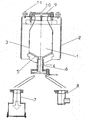
- the melt layer is designated, which is inserted through a lower opening 4 via the designated 5 channels.
- 6 with a lower closure piece is referred to which optionally a collecting container 7 for melt or a connection 8 for the discharge of the resulting exhaust gas can be coupled.
- 9 is an upper closure piece, which has a connection 10 for the supply of an inert gas, for example nitrogen.
- eye bolts are designated, which allow lifting of the blow head for the introduction of the connector 6. The blow head can also be lifted with a forklift that attacks on its underside.
Landscapes
- Engineering & Computer Science (AREA)
- Mechanical Engineering (AREA)
- Extrusion Moulding Of Plastics Or The Like (AREA)
- Processing And Handling Of Plastics And Other Materials For Molding In General (AREA)
- Cleaning In General (AREA)
- Moulds For Moulding Plastics Or The Like (AREA)
- Casting Or Compression Moulding Of Plastics Or The Like (AREA)
Description
- Die Erfindung bezieht sich auf ein Verfahren zur Reinigung eines Blaskopfes für Kunststofffolien, der während der Herstellung von Folien durch eine Heizung auf Betriebstemperatur gehalten wird. Die Erfindung bezieht sich auch auf eine Vorrichtung zur Durchführung des Verfahrens.
- Blasköpfe werden eingesetzt, um aus einem runden Schmelzestrang, wie er aus einem Extruder austritt, eine Ringdüse anzuspeisen. Die Blasköpfe werden in Ausführungen für eine Schmelzeschicht als Monoblasköpfe und für mehrere Schichten als Coextrusionsblasköpfe eingesetzt. Die Blasköpfe müssen nach bestimmten Produktionsintervallen gereinigt werden. Bei der Reinigung muss der Kunststoff vollständig aus dem Blaskopf entfernt werden. Es sind bereits Verfahren zur Reinigung von polymerbehaftete Teile bekannt. Eines der bekannten Verfahren beruht auf einer Wirbelbettreinigung. Das zu reinigende Bauteil wird in ein Bett aus Quarzsand gehängt. Der Quarzsand liegt auf einem Düsenboden, durch den ein Brenngas-Luft-Gemisch geblasen wird. Das durchströmende, brennende Gas führt dazu, dass der Sand turbulente Bewegungen ausführt. Der Reinigungseffekt ergibt sich aus der hohen Temperatur des Sandes und der abrasiven Wirkung der Strömung des Sandes.
- Das Dokument US-A-5 485 858 beschreibt ein Verfahren zum Reinigen von Teilen von Kunststoffverarbeitungsmaschinen, u.a. Blasköpfen, an denen Kunststoffreste anhaften, durch Einbringen der Teile in ein über die Schmelz- oder Zersetzungstemperatur der Kunststoffteile erhitztes Wärmeträgermedium.
- Bei einem weiteren bekannten Verfahren wird die Reinigung in einer Unterdruckkammer unter Ausschluss von Sauerstoff durchgeführt. Der Blaskopf wird über Strahlungsheizungen erhitzt. Ein Teil der Kunststoffschmelze fließt aus dem Blaskopf aus. Nachfolgend wird die Temperatur weiter erhöht. Die verbleibende Schmelze zersetzt sich durch ein Cracken der Makromoleküle in die Monomere z. B. CH4, C2H6, CO, CO4, H2. Die dabei entstehenden Gase werden über einen Katalysator abgeführt und zu CO2 und H2O umgewandelt. Gegenüber dem Wirbelbettverfahren ist auch die Reinigung der inneren Bereiche des Blaskopfes möglich.
- Nachteilig bei den o.g. Verfahren ist die Tatsache, dass der Blaskopf vor der Reinigung völlig demontiert werden muss. Bei dem Wirbelbettverfahren können nur die Bereiche des Bauteiles gereinigt werden, die vom Reinigungssand erreicht werden.
- Bei dem zweiten bekannte Verfahren besteht der Nachteil, dass der Blaskopf nur über Strahlungsheizungen erhitzt wird. Durch das im Vergleich zum freien Volumen im Blaskopf große Volumen im Reinigungsofen wird eine Verringerung des Sauerstoffanteiles in der umgebenden Luft erheblich erschwert. Bei der Demontage des Blaskopfes aus der Extrusionsanlage müssen auch sämtliche Zusatzkomponenten wie Temperatursensoren und Heizungsbänder entfernt werden. Der Investitionsaufwand für solche Vakuumreinigungsanlagen ist sehr hoch.
- Aufgabe der Erfindung ist es, eine Reinigung eines Blaskopfes für Kunststofffolien so auszugestalten, dass sämtliche Bereiche, die mit Kunststoff bei der Herstellung von Folien in Berührung kommen, gereinigt werden können und der Aufwand wesentlich beschränkt wird.
- Diese Aufgabe wird bei einem Verfahren der eingangs erläuterten Art erfindungsgemäß dadurch gelöst, dass zunächst in einer ersten Phase der Blaskopf nach Beendigung des Herstellungsvorganges durch die vorhandene Heizung auf eine oberhalb der Schmelztemperatur des im Blaskopf verbliebenen Kunststoffes zur Verflüssigung desselben erhitzt wird, dass spätestens nachdem Ablaufen des verflüssigten Kunststoffes zumindest der mit Kunststoff in Berührung stehende Bereich des Blaskopfes in einer zweiten Phase von der Umgebungsatmosphäre abgeschlossen und von seiner sauerstoffhaltigen Atmosphäre befreit und weit über die Zersetzungstemperatur des noch verbliebenen Kunststoffes erhitzt wird und die dabei anfallenden gasförmigen Produkte abgeführt werden und dass am Ende der Zersetzungsphase des verbliebenen Kunststoffes der Blaskopf mit einem Gas durchspült wird, das zumindest einen Anteil an Sauerstoff enthält, um eine Veraschung von Restpartikeln durchzuführen.
- Diese Verfahrensart bringt mehrere Vorteile mit sich. Da die am Blaskopf für die Herstellung der Folien erforderliche Heizung für den Reinigungsvorgang benutzt wird, ist eine zusätzliche Investition, beispielsweise für Strahlungsheizungen und für eine Vakuumkammer, nicht mehr erforderlich. Weiterhin kann die Restwärme des Blaskopfes genutzt werden, da sich die Reinigungsphase unmittelbar an die Produktion anschließen kann.
- In weiterer Ausgestaltung der Erfindung ist vorgesehen, dass zum Abschließen des mit Kunststoffen in Berührung stehenden Bereiches des Blaskopfes von der Atmosphäre, die Ein- und Austrittsöffnungen für die Kunststoffschmelze mit Verschlussstücken verschlossen werden, die Anschlüsse für die Zuführung von Inertgas und eines sauerstoffhaltigen Gases sowie Anschlüsse für die Abfuhr der Schmelze für die Abführung von anfallenden Abgasen und für die Evakuierung dieses Bereiches aufweisen.
- Wenn in Weiterbildung der Erfindung für die Reinigung des Blaskopfes dieser in der Extrusionsanlage verbleibt, so ist hierdurch ein erheblicher Demontageaufwand vermieden worden, der notwendig ist, um die zu reinigenden Teile entweder in ein Wirbelbett oder in eine Vakuumkammer zu verbringen, wobei bei dieser Demontage auch die Zuführungsleitungen für Temperaturfühler und die Heizung entfernt und wieder angebracht werden müssen. Das Verbleiben des Blaskopfes in der Extrusionsanlage verringert die Montagezeit und den Aufwand für zusätzliche Anlagen, wie z. B. Unterdruckkammern, derart, dass die notwendigen Investitionskosten bereits für eine Anlage wirtschaftlich vertretbar sind.
- In Weiterbildung der Erfindung kann zur Erzielung einer sauerstofffreien Atmosphäre im Blaskopf dieser mit einem inerten Gas durchspült werden. Weiterhin ist es möglich, zur Erzielung einer sauerstofffreien Atmosphäre im Blaskopf diesen zu evakuieren.
- Es kann vorteilhaft sein, den Spülvorgang mit Inertgas bereits mit Beginn des Reinigungsvorganges nach Anspruch 1 durchzuführen.
- Das sauerstoffhaltige Spülgas kann in vorteilhafter Weise Umgebungsluft, mit Sauerstoff angereicherte Umgebungsluft oder reiner Sauerstoff sein.
- Eine Vorrichtung zur Durchführung des Verfahrens ist dadurch gekennzeichnet, dass der Blaskopf mit einem unteren Verschlussstück ausgeführt ist, das wahlweise eine Schmelzezuführung, eine Schmelzeabführung und eine Gasabführung gestattet. In diesem Falle ist es nicht notwendig, den Blaskopf von der Schmelzezuführung zu lösen, um dieses Verschlussstück anzubringen, was den Montageaufwand bei jeder Reinigung vermindert.
- Es ist aber auch möglich, dass der Blaskopf lösbar mit der Schmelzezuführung verbunden und von dieser zur Einführung eines Verschlussstückes mit Einrichtungen zum Anheben ausgebildet ist. Der Montageaufwand beschränkt sich dabei auf das Lösen des Blaskopfes von der Schmelzezuführung und das Anheben desselben, um ein Verschlussstück mit den entsprechenden Anschlüssen für die Schmelzeabführung oder die Abführung des anfallenden Abgases anzubringen.
- Die Erfindung wird nachfolgend anhand eines Ausführungsbeispieles näher erläutert, das in der Zeichnung anhand einer einzelnen Figur dargestellt ist. Diese zeigt einen Schnitt durch einen Blaskopf mit den für die Reinigung notwendigen Verschlussstücken.
- Wie aus der Zeichnung ersichtlich, weist ein insgesamt mit 1 bezeichneter Blaskopf Heizbänder 2 auf, die ein Aufheizen des Blaskopfes bis zur Zersetzungstemperatur des in diesem nach der Produktion verbleibenden Kunststoffes gestattet. Mit 3 ist die Schmelzeschicht bezeichnet, die durch eine untere Öffnung 4 über die mit 5 bezeichneten Kanäle einführbar ist. Mit 6 ist ein unteres Verschlussstück bezeichnet, an welches wahlweise ein Auffangbehälter 7 für Schmelze oder ein Anschluss 8 für die Abführung des anfallenden Abgases ankuppelbar ist. Mit 9 ist ein oberes Verschlussstück bezeichnet, welches einen Anschluss 10 für die Zuführung von einem inerten Gas, beispielsweise Stickstoff, aufweist. Mit dem Bezugszeichen 11 sind Ringschrauben bezeichnet, die ein Anheben des Blaskopfes zur Einführung des Anschlussstückes 6 ermöglichen. Der Blaskopf kann auch mit einem Gabelstapler, der an seiner Unterseite angreift, angehoben werden.
Claims (9)
- Verfahren zur Reinigung eines Blaskopfes (1) für Kunststofffolien, der während der Herstellung der Folien durch eine Heizung auf Betriebstemperatur gehalten wird, dadurch gekennzeichnet, dass zunächst in einer ersten Phase der Blaskopf (1) nach Beendigung des Herstellungsvorganges durch die vorhandene Heizung auf eine oberhalb der Schmelztemperatur des im Blaskopf (1) verbliebenen Kunststoffes zur Verflüssigung desselben erhitzt wird, dass spätestens nach dem Ablaufen des verflüssigten Kunststoffes zumindest der mit Kunststoff in Berührung stehende Bereich des Blaskopfes (1) in einer zweiten Phase von der Umgebungsatmosphäre abgeschlossen und von seiner sauerstoffhaltigen Atmosphäre befreit und weit über die Zersetzungstemperatur des noch verbliebenen Kunststoffes erhitzt wird und die dabei anfallenden gasförmigen Produkte abgeführt werden und dass am Ende der Zersetzungsphase des verbliebenen Kunststoffes der Blaskopf (1) mit einem Gas durchspült wird, das zumindest einen Anteil an Sauerstoff enthält, um eine Veraschung von Restpartikeln durchzuführen.
- Verfahren nach Anspruch 1, dadurch gekennzeichnet, dass zum Abschließen des mit Kunststoff in Berührung stehenden Bereiches des Blaskopfes (1) von der Atmosphäre die Ein- und Austrittsöffnungen für die Kunststoffschmelze mit Verschlussstücken verschlossen werden, die Anschlüsse für die Zuführung von Inertgas und eines sauerstoffhaltigen Gases sowie Anschlüsse für die Abfuhr der Schmelze, für die Abführung von anfallenden Abgasen und für die Evakuierung dieses Bereiches, aufweisen.
- Verfahren nach Anspruch 1 oder 2, dadurch gekennzeichnet, dass für die Reinigung des Blaskopfes (1) dieser in der Extrusionsanlage verbleibt.
- Verfahren nach einem der Ansprüche 1 bis 3, dadurch gekennzeichnet, dass zur Erzielung einer sauerstofffreien Atmosphäre im Blaskopf (1) dieser mit einem inerten Gas durchspült wird.
- Verfahren nach einem der Ansprüche 1 bis 3, dadurch gekennzeichnet, dass zur Erzielung einer sauerstofffreien Atmosphäre im Blaskopf (1) dieser evakuiert wird.
- Verfahren nach Anspruch 4, dadurch gekennzeichnet, dass der Spülvorgang mit Inertgas bereits mit Beginn des Reinigungsvorganges nach Anspruch 1 durchgeführt wird.
- Verfahren nach einem der Ansprüche 1 bis 6, dadurch gekennzeichnet, dass das sauerstoffhaltige Spülgas Umgebungsluft, mit Sauerstoff angereicherte Umgebungsluft oder reiner Sauerstoff ist.
- Vorrichtung zur Durchführung des Verfahrens nach einem der Ansprüche 1 bis 7, dadurch gekennzeichnet, dass der Blaskopf (1) mit einem unteren Verschlussstück (6) ausgeführt ist, das wahlweise eine Schmelzezuführung, eine Schmelzeabführung und eine Gasabführung gestattet.
- Vorrichtung zur Durchführung des Verfahrens nach einem der Ansprüche 1 bis 7, dadurch gekennzeichnet, dass der Blaskopf (1) lösbar mit der Schmelzezuführung verbunden und von dieser zur Einführung eines Verschlussstückes (6) mit Einrichtungen (11) zum Anheben ausgebildet ist.
Applications Claiming Priority (2)
| Application Number | Priority Date | Filing Date | Title |
|---|---|---|---|
| DE102004007929A DE102004007929B4 (de) | 2004-02-18 | 2004-02-18 | Verfahren und Vorrichtung zur Reinigung eines Blaskopfes für Kunststofffolien |
| DE102004007929 | 2004-02-18 |
Publications (2)
| Publication Number | Publication Date |
|---|---|
| EP1566256A1 EP1566256A1 (de) | 2005-08-24 |
| EP1566256B1 true EP1566256B1 (de) | 2006-07-12 |
Family
ID=34706836
Family Applications (1)
| Application Number | Title | Priority Date | Filing Date |
|---|---|---|---|
| EP05001440A Expired - Lifetime EP1566256B1 (de) | 2004-02-18 | 2005-01-25 | Verfahren und Vorrichtung zur Reinigung eines Blaskopfes für Kunststofffolien |
Country Status (6)
| Country | Link |
|---|---|
| US (1) | US7540291B2 (de) |
| EP (1) | EP1566256B1 (de) |
| AT (1) | ATE332794T1 (de) |
| CA (1) | CA2497472C (de) |
| DE (2) | DE102004007929B4 (de) |
| ES (1) | ES2268671T3 (de) |
Families Citing this family (10)
| Publication number | Priority date | Publication date | Assignee | Title |
|---|---|---|---|---|
| AU2004100000A4 (en) | 2004-01-02 | 2004-02-12 | Sands Innovations Pty Ltd | Dispensing stirring implement |
| AU2008210267B2 (en) | 2007-01-31 | 2014-06-12 | Sands Innovations Pty Ltd | A dispensing utensil and manufacturing method therefor |
| AU2008365185B2 (en) | 2008-12-09 | 2016-05-05 | Sands Innovations Pty Ltd | A dispensing container |
| USD636890S1 (en) | 2009-09-17 | 2011-04-26 | Sands Innovations Pty. Ltd. | Dispensing utensil |
| US8511500B2 (en) | 2010-06-07 | 2013-08-20 | Sands Innovations Pty. Ltd. | Dispensing container |
| US8485360B2 (en) | 2011-03-04 | 2013-07-16 | Sands Innovations Pty, Ltd. | Fracturable container |
| CN110270559A (zh) * | 2019-06-21 | 2019-09-24 | 中国神华能源股份有限公司 | 除雪装置及轨边检测设备 |
| CN112080620B (zh) * | 2020-08-19 | 2022-06-17 | 平顶山神马工程塑料有限责任公司 | 用于提升聚合釜排气阀保压能力的处理方法 |
| JP2025075468A (ja) * | 2023-10-31 | 2025-05-15 | セイコーエプソン株式会社 | 吐出部のメンテナンス方法 |
| CN118681876B (zh) * | 2024-08-23 | 2024-10-29 | 中国化学工程第十三建设有限公司 | 一种填充管道试压吹扫一体化设备及其使用方法 |
Family Cites Families (11)
| Publication number | Priority date | Publication date | Assignee | Title |
|---|---|---|---|---|
| US2917418A (en) * | 1958-03-13 | 1959-12-15 | Eastman Kodak Co | Thermolytic process for cleaning apparatus used in processing polyethylene terephthalate |
| US3228064A (en) * | 1963-05-17 | 1966-01-11 | Cyril Adams & Company Ltd | Extruding or compounding machine for plastic materials |
| CA1098072A (en) * | 1977-06-06 | 1981-03-24 | Thomas S. Dwan | Process for vacuum pyrolysis removal of polymers from various objects |
| CH635250A5 (de) * | 1977-08-12 | 1983-03-31 | Schweizerische Viscose | Verfahren und vorrichtung zur entfernung von rueckstaenden auf geraeten durch pyrolyse. |
| JPS5924847B2 (ja) * | 1981-03-09 | 1984-06-12 | 東レ株式会社 | 金属フイルタ−の再生方法 |
| JPS58149919A (ja) * | 1982-03-01 | 1983-09-06 | Toray Ind Inc | 熱可塑性樹脂除去装置 |
| IT1151197B (it) * | 1982-05-21 | 1986-12-17 | Cge Comp Gen Elettromecc | Interruttore a limitazione di corrente avente un perfezionato sistema di contatti |
| DE3425371C2 (de) * | 1984-07-10 | 1986-05-07 | Windmöller & Hölscher, 4540 Lengerich | Folienblaskopf für die Herstellung von Schlauchfolien |
| DE8816444U1 (de) * | 1988-05-27 | 1989-08-24 | C. Christ Abgasfreie Werkzeugreinigungsapparate für die Kunststoffindustrie, 8000 München | Vorrichtung zum Reinigen solcher Teile von Kunststoffverarbeitungsmaschinen, an denen Kunststoffreste anhaften |
| DE4302415C1 (de) * | 1993-01-28 | 1993-12-09 | Christ Caroline | Verfahren und Vorrichtung zum Reinigen von Teilen von Kunststoffverarbeitungsmaschinen |
| JPH11207278A (ja) * | 1998-01-23 | 1999-08-03 | Daihatsu Motor Co Ltd | ブロー造型機のブローヘッド清掃装置 |
-
2004
- 2004-02-18 DE DE102004007929A patent/DE102004007929B4/de not_active Expired - Fee Related
-
2005
- 2005-01-25 EP EP05001440A patent/EP1566256B1/de not_active Expired - Lifetime
- 2005-01-25 AT AT05001440T patent/ATE332794T1/de not_active IP Right Cessation
- 2005-01-25 ES ES05001440T patent/ES2268671T3/es not_active Expired - Lifetime
- 2005-01-25 DE DE502005000033T patent/DE502005000033D1/de not_active Expired - Fee Related
- 2005-02-17 CA CA002497472A patent/CA2497472C/en not_active Expired - Fee Related
- 2005-02-17 US US11/059,923 patent/US7540291B2/en not_active Expired - Fee Related
Also Published As
| Publication number | Publication date |
|---|---|
| DE102004007929B4 (de) | 2006-03-30 |
| DE502005000033D1 (de) | 2006-08-24 |
| DE102004007929A1 (de) | 2005-09-08 |
| US7540291B2 (en) | 2009-06-02 |
| EP1566256A1 (de) | 2005-08-24 |
| ATE332794T1 (de) | 2006-08-15 |
| CA2497472A1 (en) | 2005-08-18 |
| ES2268671T3 (es) | 2007-03-16 |
| CA2497472C (en) | 2008-04-22 |
| US20050178407A1 (en) | 2005-08-18 |
Similar Documents
| Publication | Publication Date | Title |
|---|---|---|
| EP1404434B1 (de) | Verfahren und vorrichtung zur abreinigung von filtern für staubbelastete abgase | |
| DE3441382C2 (de) | ||
| EP1566256A1 (de) | Verfahren und Vorrichtung zur Reinigung eines Blaskopfes für Kunststofffolien | |
| DE2251007A1 (de) | Verfahren und vorrichtung zur veraschung radioaktiver abfaelle und zur vorbereitung brennbarer abfaelle zur umweltschuetzenden lagerung | |
| DE2623823A1 (de) | Vorrichtung zur zufuehrung von granulat- oder pulverfoermigen kunststoffen unter vakuum | |
| DE69416726T2 (de) | Verfahren und Vorrichtung zur thermischen Reinigung von Objekten | |
| DE4208151C2 (de) | Verfahren zur Verringerung der Betriebsmittelverschmutzung bei Vakuumpumpen bei der Reinigung von Abgasen, insbesondere aus Vakuumpyrolyseanlagen | |
| EP2209604B1 (de) | Verfahren zum extrudieren von kunststoffteilen | |
| EP1970145A2 (de) | Verfahren zur Entlüftung von Formen | |
| EP0191718A1 (de) | Verfahren zur Reinigung von Filterelementen | |
| DE60021936T2 (de) | Zentrifuge mit Pneumatikantrieb und Filtration ihrer Gehäuseatmosphäre | |
| DE3728487C2 (de) | Verfahren zur pyrolytischen Behandlung von Abfall- oder Schadstoffen | |
| DE2804616A1 (de) | Verfahren und vorrichtung zum pyrolytischen abbauen eines organischen materials | |
| DE102011001298A1 (de) | Verfahren zur Adsorption von Geruchsemissionen aus der Kautschukverarbeitung | |
| DE2406314C3 (de) | Vorrichtung zum Absaugen, Verbrennen und Auswaschen von Gas zur Verwendung an einem Koksofen | |
| DE3816077C2 (de) | Verfahren und Vorrichtung zur Abreinigung eines Staubfilters | |
| EP3453514A1 (de) | Vorrichtung und verfahren zum filtern und entgasen einer kunststoffschmelze | |
| EP3145622B1 (de) | Vorrichtung und verfahren zur behandlung eines gasstroms | |
| DE102020003888A1 (de) | Vorrichtung und Verfahren zur additiven Fertigung unter Schutzgas | |
| EP2363264A1 (de) | Verfahren zum Spitzgießen von Kunststoffteilen | |
| DE2516597C2 (de) | Am fuellwagen angeordnete reinigungsvorrichtung fuer die wandungen der fuelloecher und/oder die sitzflaechen der fuellochdeckel von verkokungsoefen | |
| DE19937733C2 (de) | Verfahren und Vorrichtung zur kontinuierlichen Übergabe von Schüttgütern aus einem Primärgaskreislauf in einen Sekundärkreislauf | |
| DE3602555C2 (de) | ||
| DE2724058A1 (de) | Verfahren zum fuellen von druckgasflaschen und eine vorrichtung dazu | |
| DE4128043A1 (de) | Anlage fuer die entlackung von lackierten blechen und anderen lackierten metallteilen, insbesondere von altautoblechen |
Legal Events
| Date | Code | Title | Description |
|---|---|---|---|
| PUAI | Public reference made under article 153(3) epc to a published international application that has entered the european phase |
Free format text: ORIGINAL CODE: 0009012 |
|
| AK | Designated contracting states |
Kind code of ref document: A1 Designated state(s): AT BE BG CH CY CZ DE DK EE ES FI FR GB GR HU IE IS IT LI LT LU MC NL PL PT RO SE SI SK TR |
|
| AX | Request for extension of the european patent |
Extension state: AL BA HR LV MK YU |
|
| GRAP | Despatch of communication of intention to grant a patent |
Free format text: ORIGINAL CODE: EPIDOSNIGR1 |
|
| 17P | Request for examination filed |
Effective date: 20050906 |
|
| GRAS | Grant fee paid |
Free format text: ORIGINAL CODE: EPIDOSNIGR3 |
|
| AKX | Designation fees paid |
Designated state(s): AT BE BG CH CY CZ DE DK EE ES FI FR GB GR HU IE IS IT LI LT LU MC NL PL PT RO SE SI SK TR |
|
| GRAA | (expected) grant |
Free format text: ORIGINAL CODE: 0009210 |
|
| AK | Designated contracting states |
Kind code of ref document: B1 Designated state(s): AT BE BG CH CY CZ DE DK EE ES FI FR GB GR HU IE IS IT LI LT LU MC NL PL PT RO SE SI SK TR |
|
| PG25 | Lapsed in a contracting state [announced via postgrant information from national office to epo] |
Ref country code: IT Free format text: LAPSE BECAUSE OF FAILURE TO SUBMIT A TRANSLATION OF THE DESCRIPTION OR TO PAY THE FEE WITHIN THE PRESCRIBED TIME-LIMIT;WARNING: LAPSES OF ITALIAN PATENTS WITH EFFECTIVE DATE BEFORE 2007 MAY HAVE OCCURRED AT ANY TIME BEFORE 2007. THE CORRECT EFFECTIVE DATE MAY BE DIFFERENT FROM THE ONE RECORDED. Effective date: 20060712 Ref country code: SK Free format text: LAPSE BECAUSE OF FAILURE TO SUBMIT A TRANSLATION OF THE DESCRIPTION OR TO PAY THE FEE WITHIN THE PRESCRIBED TIME-LIMIT Effective date: 20060712 Ref country code: PL Free format text: LAPSE BECAUSE OF FAILURE TO SUBMIT A TRANSLATION OF THE DESCRIPTION OR TO PAY THE FEE WITHIN THE PRESCRIBED TIME-LIMIT Effective date: 20060712 Ref country code: FI Free format text: LAPSE BECAUSE OF FAILURE TO SUBMIT A TRANSLATION OF THE DESCRIPTION OR TO PAY THE FEE WITHIN THE PRESCRIBED TIME-LIMIT Effective date: 20060712 Ref country code: RO Free format text: LAPSE BECAUSE OF FAILURE TO SUBMIT A TRANSLATION OF THE DESCRIPTION OR TO PAY THE FEE WITHIN THE PRESCRIBED TIME-LIMIT Effective date: 20060712 Ref country code: SI Free format text: LAPSE BECAUSE OF FAILURE TO SUBMIT A TRANSLATION OF THE DESCRIPTION OR TO PAY THE FEE WITHIN THE PRESCRIBED TIME-LIMIT Effective date: 20060712 Ref country code: CZ Free format text: LAPSE BECAUSE OF FAILURE TO SUBMIT A TRANSLATION OF THE DESCRIPTION OR TO PAY THE FEE WITHIN THE PRESCRIBED TIME-LIMIT Effective date: 20060712 Ref country code: IS Free format text: LAPSE BECAUSE OF FAILURE TO SUBMIT A TRANSLATION OF THE DESCRIPTION OR TO PAY THE FEE WITHIN THE PRESCRIBED TIME-LIMIT Effective date: 20060712 Ref country code: IE Free format text: LAPSE BECAUSE OF FAILURE TO SUBMIT A TRANSLATION OF THE DESCRIPTION OR TO PAY THE FEE WITHIN THE PRESCRIBED TIME-LIMIT Effective date: 20060712 Ref country code: LT Free format text: LAPSE BECAUSE OF FAILURE TO SUBMIT A TRANSLATION OF THE DESCRIPTION OR TO PAY THE FEE WITHIN THE PRESCRIBED TIME-LIMIT Effective date: 20060712 Ref country code: NL Free format text: LAPSE BECAUSE OF FAILURE TO SUBMIT A TRANSLATION OF THE DESCRIPTION OR TO PAY THE FEE WITHIN THE PRESCRIBED TIME-LIMIT Effective date: 20060712 |
|
| REG | Reference to a national code |
Ref country code: GB Ref legal event code: FG4D Free format text: NOT ENGLISH |
|
| REG | Reference to a national code |
Ref country code: CH Ref legal event code: EP |
|
| REG | Reference to a national code |
Ref country code: IE Ref legal event code: FG4D Free format text: LANGUAGE OF EP DOCUMENT: GERMAN |
|
| REF | Corresponds to: |
Ref document number: 502005000033 Country of ref document: DE Date of ref document: 20060824 Kind code of ref document: P |
|
| PG25 | Lapsed in a contracting state [announced via postgrant information from national office to epo] |
Ref country code: DK Free format text: LAPSE BECAUSE OF FAILURE TO SUBMIT A TRANSLATION OF THE DESCRIPTION OR TO PAY THE FEE WITHIN THE PRESCRIBED TIME-LIMIT Effective date: 20061012 Ref country code: BG Free format text: LAPSE BECAUSE OF FAILURE TO SUBMIT A TRANSLATION OF THE DESCRIPTION OR TO PAY THE FEE WITHIN THE PRESCRIBED TIME-LIMIT Effective date: 20061012 Ref country code: SE Free format text: LAPSE BECAUSE OF FAILURE TO SUBMIT A TRANSLATION OF THE DESCRIPTION OR TO PAY THE FEE WITHIN THE PRESCRIBED TIME-LIMIT Effective date: 20061012 |
|
| GBT | Gb: translation of ep patent filed (gb section 77(6)(a)/1977) |
Effective date: 20061019 |
|
| PG25 | Lapsed in a contracting state [announced via postgrant information from national office to epo] |
Ref country code: PT Free format text: LAPSE BECAUSE OF FAILURE TO SUBMIT A TRANSLATION OF THE DESCRIPTION OR TO PAY THE FEE WITHIN THE PRESCRIBED TIME-LIMIT Effective date: 20061212 |
|
| NLV1 | Nl: lapsed or annulled due to failure to fulfill the requirements of art. 29p and 29m of the patents act | ||
| PG25 | Lapsed in a contracting state [announced via postgrant information from national office to epo] |
Ref country code: MC Free format text: LAPSE BECAUSE OF NON-PAYMENT OF DUE FEES Effective date: 20070131 |
|
| REG | Reference to a national code |
Ref country code: IE Ref legal event code: FD4D |
|
| ET | Fr: translation filed | ||
| REG | Reference to a national code |
Ref country code: ES Ref legal event code: FG2A Ref document number: 2268671 Country of ref document: ES Kind code of ref document: T3 |
|
| PLBE | No opposition filed within time limit |
Free format text: ORIGINAL CODE: 0009261 |
|
| STAA | Information on the status of an ep patent application or granted ep patent |
Free format text: STATUS: NO OPPOSITION FILED WITHIN TIME LIMIT |
|
| 26N | No opposition filed |
Effective date: 20070413 |
|
| PG25 | Lapsed in a contracting state [announced via postgrant information from national office to epo] |
Ref country code: DE Free format text: LAPSE BECAUSE OF NON-PAYMENT OF DUE FEES Effective date: 20070801 |
|
| BERE | Be: lapsed |
Owner name: KIEFEL EXTRUSION G.M.B.H. Effective date: 20070131 |
|
| PG25 | Lapsed in a contracting state [announced via postgrant information from national office to epo] |
Ref country code: BE Free format text: LAPSE BECAUSE OF NON-PAYMENT OF DUE FEES Effective date: 20070131 |
|
| PG25 | Lapsed in a contracting state [announced via postgrant information from national office to epo] |
Ref country code: GR Free format text: LAPSE BECAUSE OF FAILURE TO SUBMIT A TRANSLATION OF THE DESCRIPTION OR TO PAY THE FEE WITHIN THE PRESCRIBED TIME-LIMIT Effective date: 20061013 |
|
| PG25 | Lapsed in a contracting state [announced via postgrant information from national office to epo] |
Ref country code: AT Free format text: LAPSE BECAUSE OF NON-PAYMENT OF DUE FEES Effective date: 20070125 |
|
| PG25 | Lapsed in a contracting state [announced via postgrant information from national office to epo] |
Ref country code: EE Free format text: LAPSE BECAUSE OF FAILURE TO SUBMIT A TRANSLATION OF THE DESCRIPTION OR TO PAY THE FEE WITHIN THE PRESCRIBED TIME-LIMIT Effective date: 20060712 |
|
| PGRI | Patent reinstated in contracting state [announced from national office to epo] |
Ref country code: IT Effective date: 20090301 |
|
| PG25 | Lapsed in a contracting state [announced via postgrant information from national office to epo] |
Ref country code: LU Free format text: LAPSE BECAUSE OF NON-PAYMENT OF DUE FEES Effective date: 20070125 Ref country code: CY Free format text: LAPSE BECAUSE OF FAILURE TO SUBMIT A TRANSLATION OF THE DESCRIPTION OR TO PAY THE FEE WITHIN THE PRESCRIBED TIME-LIMIT Effective date: 20060712 |
|
| REG | Reference to a national code |
Ref country code: CH Ref legal event code: PL |
|
| PG25 | Lapsed in a contracting state [announced via postgrant information from national office to epo] |
Ref country code: HU Free format text: LAPSE BECAUSE OF FAILURE TO SUBMIT A TRANSLATION OF THE DESCRIPTION OR TO PAY THE FEE WITHIN THE PRESCRIBED TIME-LIMIT Effective date: 20070113 Ref country code: TR Free format text: LAPSE BECAUSE OF FAILURE TO SUBMIT A TRANSLATION OF THE DESCRIPTION OR TO PAY THE FEE WITHIN THE PRESCRIBED TIME-LIMIT Effective date: 20060712 |
|
| PG25 | Lapsed in a contracting state [announced via postgrant information from national office to epo] |
Ref country code: LI Free format text: LAPSE BECAUSE OF NON-PAYMENT OF DUE FEES Effective date: 20090131 Ref country code: CH Free format text: LAPSE BECAUSE OF NON-PAYMENT OF DUE FEES Effective date: 20090131 |
|
| PGFP | Annual fee paid to national office [announced via postgrant information from national office to epo] |
Ref country code: ES Payment date: 20140109 Year of fee payment: 10 Ref country code: FR Payment date: 20140121 Year of fee payment: 10 |
|
| PGFP | Annual fee paid to national office [announced via postgrant information from national office to epo] |
Ref country code: GB Payment date: 20140123 Year of fee payment: 10 |
|
| PGFP | Annual fee paid to national office [announced via postgrant information from national office to epo] |
Ref country code: IT Payment date: 20150122 Year of fee payment: 11 |
|
| GBPC | Gb: european patent ceased through non-payment of renewal fee |
Effective date: 20150125 |
|
| PG25 | Lapsed in a contracting state [announced via postgrant information from national office to epo] |
Ref country code: GB Free format text: LAPSE BECAUSE OF NON-PAYMENT OF DUE FEES Effective date: 20150125 |
|
| REG | Reference to a national code |
Ref country code: FR Ref legal event code: ST Effective date: 20150930 |
|
| PG25 | Lapsed in a contracting state [announced via postgrant information from national office to epo] |
Ref country code: FR Free format text: LAPSE BECAUSE OF NON-PAYMENT OF DUE FEES Effective date: 20150202 |
|
| REG | Reference to a national code |
Ref country code: ES Ref legal event code: FD2A Effective date: 20160527 |
|
| PG25 | Lapsed in a contracting state [announced via postgrant information from national office to epo] |
Ref country code: ES Free format text: LAPSE BECAUSE OF NON-PAYMENT OF DUE FEES Effective date: 20150126 |
|
| PG25 | Lapsed in a contracting state [announced via postgrant information from national office to epo] |
Ref country code: IT Free format text: LAPSE BECAUSE OF FAILURE TO SUBMIT A TRANSLATION OF THE DESCRIPTION OR TO PAY THE FEE WITHIN THE PRESCRIBED TIME-LIMIT Effective date: 20160125 |