EP1566237B1 - Bearbeitungseinspannvorrichtung - Google Patents
Bearbeitungseinspannvorrichtung Download PDFInfo
- Publication number
- EP1566237B1 EP1566237B1 EP05002598A EP05002598A EP1566237B1 EP 1566237 B1 EP1566237 B1 EP 1566237B1 EP 05002598 A EP05002598 A EP 05002598A EP 05002598 A EP05002598 A EP 05002598A EP 1566237 B1 EP1566237 B1 EP 1566237B1
- Authority
- EP
- European Patent Office
- Prior art keywords
- pallet
- bolt
- jig
- work
- machining
- Prior art date
- Legal status (The legal status is an assumption and is not a legal conclusion. Google has not performed a legal analysis and makes no representation as to the accuracy of the status listed.)
- Expired - Lifetime
Links
- 238000003754 machining Methods 0.000 title claims description 25
- 238000000034 method Methods 0.000 description 1
Images


Classifications
-
- B—PERFORMING OPERATIONS; TRANSPORTING
- B23—MACHINE TOOLS; METAL-WORKING NOT OTHERWISE PROVIDED FOR
- B23Q—DETAILS, COMPONENTS, OR ACCESSORIES FOR MACHINE TOOLS, e.g. ARRANGEMENTS FOR COPYING OR CONTROLLING; MACHINE TOOLS IN GENERAL CHARACTERISED BY THE CONSTRUCTION OF PARTICULAR DETAILS OR COMPONENTS; COMBINATIONS OR ASSOCIATIONS OF METAL-WORKING MACHINES, NOT DIRECTED TO A PARTICULAR RESULT
- B23Q3/00—Devices holding, supporting, or positioning work or tools, of a kind normally removable from the machine
- B23Q3/02—Devices holding, supporting, or positioning work or tools, of a kind normally removable from the machine for mounting on a work-table, tool-slide, or analogous part
- B23Q3/10—Auxiliary devices, e.g. bolsters, extension members
- B23Q3/103—Constructional elements used for constructing work holders
Definitions
- the present invention relates to a machining jig for attaching a work, which is used in a machining center functioning as a multitasking machine.
- Document DE 102 14 328 A1 which represents the closest prior art, discloses a machining jig for supporting a work, comprising a jig base and a disk-shaped pallet which is fixed to the jig base, corresponding to the preamble of claim 1.
- Patent document 1 discloses a flexible machining device using a universal pallet.
- the machining jig according to the present invention is composed of a pallet having a number of bolts, and a standardized jig accommodating member attached to the pallet, wherein by assembling the standardized jig accommodatingmembers according to the variation of the work, it aims at reducing the number of dedicated machining jigs.
- the machining jig according to the present invention mounted on a table of a multitasking machine for supporting a work comprises a jig base having an opening formed to a circumference thereof and a round hole at an upper portion thereof, and a disk-shaped pallet being inserted and fixed to the round hole of the jig base.
- the pallet comprises even-pitched bolt-inserting through holes, a standard bolt inserted to the through hole, and a stopper plate for preventing the bolt from falling.
- the machining jig comprises a supporting block fixed to the pallet via the standard bolt for supporting the work, and the supporting block of the machining jig comprises two screw holes to which are engaged the standard bolts inserted to the pallet, and a single through hole through which passes the bolt engaged to the work.
- the machining jig comprises a positioning block fixed to the pallet via the standard bolt and having a pin for positioning the work.
- the jigs that are used frequently are stored in their assembled states as jig plates, and the jigs that are used less frequently are assembled when necessary by a worker into a jig plate and prepared in a storage.
- This method enables the number of stored variations of plates to be reduced and both the storage space and the steps required for storage to be reduced greatly. Since the attachment of the work to the jig is realized by fastening the work onto the jig from a bottom surface using a bolt, the work is free from any deflection caused by clamping, and thus, highly accurate machining is made possible. Furthermore, since there are no jig components attached to the outer side of the work, no interference occurs with the jig.
- the present invention can be easily automated using robots.
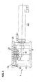
- FIG. 1 is a front view of a jig base and a pallet according to the machining jig of the present invention
- FIG. 2 is a plan view thereof.
- the machining jig is composed of a jig base 10 and a pallet 20, and the pallet 20 is fixed to the jig base 10 by bolts 30.
- a large number of bolt holes 22 are formed to the pallet 20 at predetermined intervals, and each bolt hole has a bolt 30 inserted upward thereto.
- the jig base 10 has openings 12 formed on four sides thereof, and through these openings 12, a head 61 of a bolt runner 60 attached to a robot arm is inserted to manipulate the bolts 30 within the pallet 20.
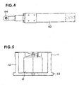
- FIG. 3 is a front view of the bolt runner
- FIG. 4 is a plan view thereof.
- the bolt runner 60 has a drive device disposed in the interior thereof for pivoting a drive shaft 62 attached to the head 61 thereof.
- the direction of rotation of the drive shaft 62 can be switched arbitrarily.
- a wrench member 64 is attached to the tip of the drive shaft 62.
- the wrench member 64 has a hexagonal wrench head which fits to a hexagonal bore formed to the bolt 30. In this state, the wrench member 64 is driven to engage and/or disengage the bolt.
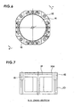
- FIG. 5 is a front view of the jig base
- FIG. 6 is a plan vie thereof
- FIG. 7 is a cross-sectional view taken at line B-B of FIG. 6.
- the jig base 10 is shaped to have flat surfaces formed to the outer circumference of a cylindrically shaped member, and on an upper flange portion 11, a round hole 14 is formed to receive a disk-shaped pallet.
- a chamfered portion 14a is formed to the inlet area of the round hole 14 for receiving the pallet smoothly.
- a lower flange portion 13 is disk-shaped, and mounted on a table of the machining center.
- the jig base 10 has four through-holes 16, and bolts are inserted to these holes 16 to fix the jig base 10 onto the upper surface of the table of the machining center.
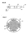
- FIG. 8 is a cross-sectional front view of the pallet 20
- FIG. 9 is an upper view thereof
- FIG. 10 is a lower view thereof.
- the pallet 20 has a flange portion 21 and a cylindrical portion 23 formed integrally to the lower area of the flange portion 21, and the cylindrical portion 23 is inserted to the round hole 14 of the jig base 10.
- a tapered portion 23a is formed to the end of the cylindrical portion 23, which enables the pallet to be inserted smoothly to the round hole 14 of the jig base 10.
- a large number of even-pitched bolt-inserting through holes 22 are formed on the cylindrical portion 23.
- the flange portion 21 also has bolt-inserting through holes 24 and bolt holes 25 with screw threads.
- a groove 26 with a bottom is formed on the back surface of the flange portion 21.
- FIG. 11 is a perspective view showing a standard bolt to be engaged to the through holes 22 or the like on the pallet.
- the standard bolt 30 has a predetermined screw portion 31 formed to the end of a cylindrical main body, and on a head portion of the main body is formed a cylindrical head 32.
- a hexagonal hole (not shown) for receiving wrenches.
- a necessary number of standard bolts 30 of various sizes are prepared.
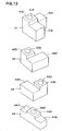
- FIG. 12 is an explanatory view showing the form of a typical block for supporting a work.
- supporting blocks 41, 42, 43 and 44 are used.
- a first supporting block 41 has a prismatic main body 410, and two attachment portions 414 and 416 extend orthogonally from the main body 410.
- a bolt through hole 412 At the center of the main body 410 is formed a bolt through hole 412.
- the upper surface of the main body 410 functions as a surface for supporting a work.
- screwholes On the back side of the two attachment portions 414 and 416 are formed screwholes (not shown) that engage with the screw portion of the bolt. Thepitchbetween the two screw holes is designed to correspond to the diagonal pitch of the bolt-inserting through holes 22 formed to the pallet 20.
- a second supporting block 42 has a prismatic main body 420 and an attachment portion 424 formed adjacent to the main body.
- the main body 420 has a bolt through hole 422.
- the height of the main body 420 is designed to correspond to the height common to all the supporting blocks.
- On the back side of the attachment portion 424 are formed two screw holes (not shown).
- the pitch between the two screw holes is designed to correspond to the pitch between adjacent bolt-inserting through holes 22 formed to the pallet 20.
- a third supporting block 43 has a prismatic main body 430 and an attachment portion 434 formed adjacent to the main body.
- the main body 430 has a bolt through hole 432.
- the height of the main body 430 is designed to correspond to the height common to all the supporting blocks.
- On the back side of the attachment portion 434 are formed two screw holes (not shown).
- the pitch between the two screw holes is designed to correspond to the pitchbetween two adj acent bolt-inserting through holes 22 formed to the pallet 20.
- a fourth supporting block 44 has a prismatic main body 440 and attachment portions 444 and 446 formed on both sides of the main body.
- the main body 440 has a bolt through hole 442.
- the height of the main body 440 is designed to correspond to the height common to all the supporting blocks.
- On the back side of the attachment portions 444 and 446 are formed two screw holes (not shown).
- the pitch between the two screw holes is designed to correspond to the pitch between two bolt-inserting through holes 22 formed to the pallet 20.
- FIG. 13 is an explanatory view of apositioningblockprepared for positioning a work on a predetermined position on the pallet 20.
- the positioning block 50 has a prismatic body and a positioning pin 51 disposed on the front end of the body.
- the positioning pin 51 has a diamond-shaped pointed tapered face.
- the rear end of the positioning block is formed to have a cylindrical boss portion 52.
- the boss 52 is inserted to a bolt hole 22 or 24 formed on the surface of the pallet 20 which also serve as positioning holes.
- a screw hole is formed to the boss portion 52, through which it can be fixed to the pallet 20 using a standard bolt 30.
- FIG. 14 is a perspective view showing an example of a work processed in the machining center using the machining jig according to the present invention.
- Awork 100 is a bracket having a structure where two orthogonal plate members 110 and 120 are coupled by triangular flanges 130. On the inner side of the plate members 110 and 120 are formed projections 140 having through holes and so on.
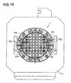
- FIG. 15 is a plan view of an exchange table of the machining center on which the machining jig according to the present invention is mounted
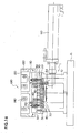
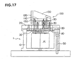
- FIG. 16 is a front view thereof
- FIG. 17 is a right side view thereof.
- the machining jig 1 having the jig base 10 and the pallet 20 connected integrally together is fixed to the surface of an exchange table T 1 using bolts 30.
- Two positioning blocks 50, 50 are fixed to the pallet 20 via bolts 30.
- the bolt tightening operation is performed automatically by rotating the wrench 64 on the bolt runner 60 attached to the robot arm.
- standard supporting blocks for supporting the work 100 are fixed to the pallet 20.
- a single second supporting block 42, a single third supporting block 43 and two fourth supporting blocks 44 are used, wherein the blocks are fixed to the pallet 20 via standard bolts 30.
- a stopper plate 80 having holes for wrenches to pass therethrough is attached to the back side of the pallet 20.
- the work 100 is securely fixed to the supporting blocks via bolts 30 using screw holes 150 formed in advance to the work 100.
- the work 100 arranged on the table of the machining center is subjected to necessary processing in the machining center.
Landscapes
- Engineering & Computer Science (AREA)
- Mechanical Engineering (AREA)
- Feeding Of Workpieces (AREA)
- Jigs For Machine Tools (AREA)
Claims (4)
- Bearbeitungseinspannvorrichtung (1), die auf einem Tisch (T1) einer Mehrzweckmaschine zur Lagerung eines Werkstücks (100) befestigt ist, umfassend:eine Einspannbasis (10) und eine scheibenförmige Palette (20), die an der Einspannbasis (10) befestigt ist,dadurch gekennzeichnet, dass die Einspannbasis (10) an ihrem Umfang eine Öffnung (12) und an einem oberen Bereich ein rundes Loch (14) aufweist, und dass die scheibenförmige Palette (20) in das runde Loch (14) der Einspannbasis (10) eingesetzt und darin befestigt ist,
und dass die Palette (20) in gleichen Abständen angeordnete Bolzeneinsatz-Durchgangslöcher (22), einen in das Durchgangsloch (22) eingesetzten Standardbolzen (30) und eine Anschlagsplatte (80) umfaßt, welche den Bolzen (30) am Herausfallen hindert. - Bearbeitungseinspannvorrichtung gemäß Anspruch 1, ferner umfassend einen Lagerblock (41,42,43,44), der an der Palette (20) durch den Standardbolzen (30) zur Lagerung des Werkstücks (100) befestigt ist.
- Bearbeitungseinspannvorrichtung gemäß Anspruch 2, bei welcher der Lagerblock (41,42,43,44) der Bearbeitungseinspannvorrichtung (1) zwei Schraublöcher aufweist, die mit den in die Palette (20) eingesetzten Standardbolzen (30) in Eingriff stehen, sowie ein einziges Durchgangsloch (412,422,432,442), welches von dem in das Werkstück (100) eingreifenden Bolzen (30) durchlaufen wird.
- Bearbeitungseinspannvorrichtung gemäß Anspruch 1, ferner umfassend einen Positionierungsblock (50), der an die Palette (20) durch den Standardbolzen (30) befestigt ist und einen Zapfen (51) zur Positionierung des Werkstücks (100) aufweist.
Applications Claiming Priority (2)
| Application Number | Priority Date | Filing Date | Title |
|---|---|---|---|
| JP2004040737A JP4326982B2 (ja) | 2004-02-18 | 2004-02-18 | 加工治具 |
| JP2004040737 | 2004-02-18 |
Publications (2)
| Publication Number | Publication Date |
|---|---|
| EP1566237A1 EP1566237A1 (de) | 2005-08-24 |
| EP1566237B1 true EP1566237B1 (de) | 2007-04-11 |
Family
ID=34709086
Family Applications (1)
| Application Number | Title | Priority Date | Filing Date |
|---|---|---|---|
| EP05002598A Expired - Lifetime EP1566237B1 (de) | 2004-02-18 | 2005-02-08 | Bearbeitungseinspannvorrichtung |
Country Status (5)
| Country | Link |
|---|---|
| US (1) | US7357385B2 (de) |
| EP (1) | EP1566237B1 (de) |
| JP (1) | JP4326982B2 (de) |
| CN (1) | CN100368146C (de) |
| DE (1) | DE602005000828T2 (de) |
Families Citing this family (9)
| Publication number | Priority date | Publication date | Assignee | Title |
|---|---|---|---|---|
| JP4326982B2 (ja) * | 2004-02-18 | 2009-09-09 | ヤマザキマザック株式会社 | 加工治具 |
| ES2318710T3 (es) * | 2006-09-20 | 2009-05-01 | Konstruktionsburo Wuthrich | Kit de construccion comprendiendo al menos una placa. |
| JP5458895B2 (ja) * | 2010-01-05 | 2014-04-02 | 株式会社ジェイテクト | 工作機械 |
| CN102513835B (zh) * | 2011-12-28 | 2013-03-20 | 江苏博大数控成套设备有限公司 | 平移式数控钻切交换工作平台 |
| CN103624568A (zh) * | 2013-11-08 | 2014-03-12 | 吴中区木渎蒯斌模具加工厂 | 多功能轴类零件综合夹具 |
| CN104002150B (zh) * | 2014-05-23 | 2016-09-14 | 苏州创丰精密五金有限公司 | 开槽工件打孔治具 |
| CN106271748A (zh) * | 2016-09-28 | 2017-01-04 | 广州凯耀资产管理有限公司 | 一种可拆卸机械加工夹具组件及其工作方法 |
| KR102459994B1 (ko) | 2018-05-21 | 2022-10-28 | 한국전자통신연구원 | 재구성 가능한 지그 장치 |
| DE102021117229B4 (de) * | 2021-07-05 | 2024-12-05 | Lang Technik Gmbh | Spannvorrichtung und Verfahren zur Handhabung eines Werkstücks |
Family Cites Families (11)
| Publication number | Priority date | Publication date | Assignee | Title |
|---|---|---|---|---|
| US2820640A (en) * | 1955-08-05 | 1958-01-21 | Neil O Regan | Master collet with replaceable soft jaws |
| GB1217741A (en) * | 1968-02-15 | 1970-12-31 | Keith Fulton Scott Thompson | Reusable constructional element for use in constructing jigs, workholders and like fixtures |
| US4828240A (en) * | 1986-09-02 | 1989-05-09 | Te-Co. | Workpiece securing apparatus for a machine tool |
| JPH08118175A (ja) * | 1994-10-21 | 1996-05-14 | Imao Corp:Kk | 取付用ベース部材及びそのベース部材に取り付けられる取付具 |
| JPH1190791A (ja) | 1997-09-11 | 1999-04-06 | Toyoda Mach Works Ltd | フレキシブル加工装置および同装置用パレット |
| US6279888B1 (en) * | 1999-04-26 | 2001-08-28 | Wal, Iii H. James Vander | Modular tooling system with radial base platform |
| JP2000323440A (ja) * | 1999-05-10 | 2000-11-24 | Disco Abrasive Syst Ltd | チャックテーブル |
| TW592882B (en) * | 2001-12-19 | 2004-06-21 | Erowa Ag | Clamping apparatus with a clamping chuck and a work piece carrier releasable connectable thereto |
| DE10214328A1 (de) * | 2002-03-28 | 2003-10-16 | Thomas Herbert Drittenpreis | Vorrichtung für die Aufnahme von zu bearbeitenden Werkstücken |
| US7044462B2 (en) * | 2003-05-02 | 2006-05-16 | Kabushiki Kaisha Imao Corporation | Fixture |
| JP4326982B2 (ja) * | 2004-02-18 | 2009-09-09 | ヤマザキマザック株式会社 | 加工治具 |
-
2004
- 2004-02-18 JP JP2004040737A patent/JP4326982B2/ja not_active Expired - Lifetime
-
2005
- 2005-02-08 EP EP05002598A patent/EP1566237B1/de not_active Expired - Lifetime
- 2005-02-08 DE DE602005000828T patent/DE602005000828T2/de not_active Expired - Lifetime
- 2005-02-11 US US11/055,429 patent/US7357385B2/en not_active Expired - Fee Related
- 2005-02-16 CN CNB2005100079885A patent/CN100368146C/zh not_active Expired - Fee Related
Also Published As
| Publication number | Publication date |
|---|---|
| US7357385B2 (en) | 2008-04-15 |
| JP2005230942A (ja) | 2005-09-02 |
| DE602005000828T2 (de) | 2008-01-10 |
| CN1657228A (zh) | 2005-08-24 |
| CN100368146C (zh) | 2008-02-13 |
| US20050179188A1 (en) | 2005-08-18 |
| JP4326982B2 (ja) | 2009-09-09 |
| EP1566237A1 (de) | 2005-08-24 |
| DE602005000828D1 (de) | 2007-05-24 |
Similar Documents
| Publication | Publication Date | Title |
|---|---|---|
| US5481811A (en) | Universal inspection workpiece holder | |
| US9889530B2 (en) | Clamp mounting system | |
| US5921534A (en) | Detachable jaw for vise-like workholding apparatus | |
| US5199836A (en) | T-nut | |
| JP3690987B2 (ja) | ワークチャッキング装置 | |
| EP1566237B1 (de) | Bearbeitungseinspannvorrichtung | |
| US8220366B1 (en) | Self-centering drive socket assembly and method | |
| US6439561B1 (en) | Modular system and fixture for positioning a workpiece | |
| US4753560A (en) | Fastener-carrier system | |
| JPH05212639A (ja) | クランプ装置 | |
| JPH0653879U (ja) | パイプ保持具 | |
| US6354179B1 (en) | Fixing device for tools | |
| EP2146390B1 (de) | Antenneneinheit | |
| US20020168237A1 (en) | Drill guide and method for drilling holes | |
| JP2020151797A (ja) | ワーク固定用治具 | |
| KR101935324B1 (ko) | 작업물 가공 방법 | |
| US5992837A (en) | Workpiece holding assembly | |
| CN217071568U (zh) | 固定基座及具有其的智能加工中心 | |
| JPH091260A (ja) | 迅速金型交換装置 | |
| JP2000005957A (ja) | 工作機械用チャック取付治具 | |
| JPS62292906A (ja) | 付属品組み立て用汎用フランジ | |
| JPH0529792Y2 (de) | ||
| CN222114034U (zh) | 一种焊接工装机构及焊接设备 | |
| CN114147267B (zh) | 用于加工空间斜面的加工装置 | |
| JPH0410993Y2 (de) |
Legal Events
| Date | Code | Title | Description |
|---|---|---|---|
| PUAI | Public reference made under article 153(3) epc to a published international application that has entered the european phase |
Free format text: ORIGINAL CODE: 0009012 |
|
| AK | Designated contracting states |
Kind code of ref document: A1 Designated state(s): AT BE BG CH CY CZ DE DK EE ES FI FR GB GR HU IE IS IT LI LT LU MC NL PL PT RO SE SI SK TR |
|
| AX | Request for extension of the european patent |
Extension state: AL BA HR LV MK YU |
|
| 17P | Request for examination filed |
Effective date: 20050827 |
|
| AKX | Designation fees paid |
Designated state(s): DE FR GB IT |
|
| GRAP | Despatch of communication of intention to grant a patent |
Free format text: ORIGINAL CODE: EPIDOSNIGR1 |
|
| GRAS | Grant fee paid |
Free format text: ORIGINAL CODE: EPIDOSNIGR3 |
|
| GRAA | (expected) grant |
Free format text: ORIGINAL CODE: 0009210 |
|
| AK | Designated contracting states |
Kind code of ref document: B1 Designated state(s): DE FR GB IT |
|
| REG | Reference to a national code |
Ref country code: GB Ref legal event code: FG4D |
|
| REF | Corresponds to: |
Ref document number: 602005000828 Country of ref document: DE Date of ref document: 20070524 Kind code of ref document: P |
|
| ET | Fr: translation filed | ||
| PLBE | No opposition filed within time limit |
Free format text: ORIGINAL CODE: 0009261 |
|
| STAA | Information on the status of an ep patent application or granted ep patent |
Free format text: STATUS: NO OPPOSITION FILED WITHIN TIME LIMIT |
|
| 26N | No opposition filed |
Effective date: 20080114 |
|
| REG | Reference to a national code |
Ref country code: FR Ref legal event code: PLFP Year of fee payment: 12 |
|
| REG | Reference to a national code |
Ref country code: FR Ref legal event code: PLFP Year of fee payment: 13 |
|
| PGFP | Annual fee paid to national office [announced via postgrant information from national office to epo] |
Ref country code: FR Payment date: 20170112 Year of fee payment: 13 Ref country code: DE Payment date: 20170131 Year of fee payment: 13 |
|
| PGFP | Annual fee paid to national office [announced via postgrant information from national office to epo] |
Ref country code: GB Payment date: 20170208 Year of fee payment: 13 |
|
| PGFP | Annual fee paid to national office [announced via postgrant information from national office to epo] |
Ref country code: IT Payment date: 20170221 Year of fee payment: 13 |
|
| REG | Reference to a national code |
Ref country code: DE Ref legal event code: R119 Ref document number: 602005000828 Country of ref document: DE |
|
| GBPC | Gb: european patent ceased through non-payment of renewal fee |
Effective date: 20180208 |
|
| REG | Reference to a national code |
Ref country code: FR Ref legal event code: ST Effective date: 20181031 |
|
| PG25 | Lapsed in a contracting state [announced via postgrant information from national office to epo] |
Ref country code: DE Free format text: LAPSE BECAUSE OF NON-PAYMENT OF DUE FEES Effective date: 20180901 |
|
| PG25 | Lapsed in a contracting state [announced via postgrant information from national office to epo] |
Ref country code: GB Free format text: LAPSE BECAUSE OF NON-PAYMENT OF DUE FEES Effective date: 20180208 Ref country code: FR Free format text: LAPSE BECAUSE OF NON-PAYMENT OF DUE FEES Effective date: 20180228 Ref country code: IT Free format text: LAPSE BECAUSE OF NON-PAYMENT OF DUE FEES Effective date: 20180208 |