EP1566195A1 - Anordnung zum Lagern, Transportieren und Applizieren einer vorzugsweise medizinischen Flüssigkeit - Google Patents
Anordnung zum Lagern, Transportieren und Applizieren einer vorzugsweise medizinischen Flüssigkeit Download PDFInfo
- Publication number
- EP1566195A1 EP1566195A1 EP05001544A EP05001544A EP1566195A1 EP 1566195 A1 EP1566195 A1 EP 1566195A1 EP 05001544 A EP05001544 A EP 05001544A EP 05001544 A EP05001544 A EP 05001544A EP 1566195 A1 EP1566195 A1 EP 1566195A1
- Authority
- EP
- European Patent Office
- Prior art keywords
- syringe barrel
- connecting element
- proximal
- closure
- syringe
- Prior art date
- Legal status (The legal status is an assumption and is not a legal conclusion. Google has not performed a legal analysis and makes no representation as to the accuracy of the status listed.)
- Granted
Links
Images


Classifications
-
- A—HUMAN NECESSITIES
- A61—MEDICAL OR VETERINARY SCIENCE; HYGIENE
- A61M—DEVICES FOR INTRODUCING MEDIA INTO, OR ONTO, THE BODY; DEVICES FOR TRANSDUCING BODY MEDIA OR FOR TAKING MEDIA FROM THE BODY; DEVICES FOR PRODUCING OR ENDING SLEEP OR STUPOR
- A61M5/00—Devices for bringing media into the body in a subcutaneous, intra-vascular or intramuscular way; Accessories therefor, e.g. filling or cleaning devices, arm-rests
- A61M5/50—Devices for bringing media into the body in a subcutaneous, intra-vascular or intramuscular way; Accessories therefor, e.g. filling or cleaning devices, arm-rests having means for preventing re-use, or for indicating if defective, used, tampered with or unsterile
- A61M5/5086—Devices for bringing media into the body in a subcutaneous, intra-vascular or intramuscular way; Accessories therefor, e.g. filling or cleaning devices, arm-rests having means for preventing re-use, or for indicating if defective, used, tampered with or unsterile for indicating if defective, used, tampered with or unsterile
-
- A—HUMAN NECESSITIES
- A61—MEDICAL OR VETERINARY SCIENCE; HYGIENE
- A61M—DEVICES FOR INTRODUCING MEDIA INTO, OR ONTO, THE BODY; DEVICES FOR TRANSDUCING BODY MEDIA OR FOR TAKING MEDIA FROM THE BODY; DEVICES FOR PRODUCING OR ENDING SLEEP OR STUPOR
- A61M5/00—Devices for bringing media into the body in a subcutaneous, intra-vascular or intramuscular way; Accessories therefor, e.g. filling or cleaning devices, arm-rests
- A61M5/002—Packages specially adapted therefor, e.g. for syringes or needles, kits for diabetics
-
- A—HUMAN NECESSITIES
- A61—MEDICAL OR VETERINARY SCIENCE; HYGIENE
- A61M—DEVICES FOR INTRODUCING MEDIA INTO, OR ONTO, THE BODY; DEVICES FOR TRANSDUCING BODY MEDIA OR FOR TAKING MEDIA FROM THE BODY; DEVICES FOR PRODUCING OR ENDING SLEEP OR STUPOR
- A61M5/00—Devices for bringing media into the body in a subcutaneous, intra-vascular or intramuscular way; Accessories therefor, e.g. filling or cleaning devices, arm-rests
- A61M5/178—Syringes
- A61M5/31—Details
- A61M2005/3103—Leak prevention means for distal end of syringes, i.e. syringe end for mounting a needle
- A61M2005/3104—Caps for syringes without needle
-
- A—HUMAN NECESSITIES
- A61—MEDICAL OR VETERINARY SCIENCE; HYGIENE
- A61M—DEVICES FOR INTRODUCING MEDIA INTO, OR ONTO, THE BODY; DEVICES FOR TRANSDUCING BODY MEDIA OR FOR TAKING MEDIA FROM THE BODY; DEVICES FOR PRODUCING OR ENDING SLEEP OR STUPOR
- A61M5/00—Devices for bringing media into the body in a subcutaneous, intra-vascular or intramuscular way; Accessories therefor, e.g. filling or cleaning devices, arm-rests
- A61M5/178—Syringes
- A61M5/28—Syringe ampoules or carpules, i.e. ampoules or carpules provided with a needle
- A61M5/285—Syringe ampoules or carpules, i.e. ampoules or carpules provided with a needle with sealing means to be broken or opened
-
- A—HUMAN NECESSITIES
- A61—MEDICAL OR VETERINARY SCIENCE; HYGIENE
- A61M—DEVICES FOR INTRODUCING MEDIA INTO, OR ONTO, THE BODY; DEVICES FOR TRANSDUCING BODY MEDIA OR FOR TAKING MEDIA FROM THE BODY; DEVICES FOR PRODUCING OR ENDING SLEEP OR STUPOR
- A61M5/00—Devices for bringing media into the body in a subcutaneous, intra-vascular or intramuscular way; Accessories therefor, e.g. filling or cleaning devices, arm-rests
- A61M5/178—Syringes
- A61M5/31—Details
- A61M5/315—Pistons; Piston-rods; Guiding, blocking or restricting the movement of the rod or piston; Appliances on the rod for facilitating dosing ; Dosing mechanisms
- A61M5/31501—Means for blocking or restricting the movement of the rod or piston
- A61M5/31505—Integral with the syringe barrel, i.e. connected to the barrel so as to make up a single complete piece or unit
Definitions
- the present invention relates to an arrangement for storing, Transporting and applying a preferably medical Liquid.
- a particularly preferred application for a Such arrangement are syringes that are of a pharmaceutical Manufacturers are prefilled with a drug, so that the application of the drug practically directly from the "Transport packaging" can be done.
- the invention further relates to a tamper-evident closure for a preferably medical syringe that allows the Syringe not only for the application of the liquid, but also as an arrangement of the aforementioned type, i. So for the Storage and transportation, to use.
- EP 0 389 938 A2 shows a syringe with a syringe barrel, at its distal The end of a needle cap sits. On the needle cap a cap sleeve is pushed, the proximal end with glued or welded to the syringe barrel. After this Turning off the cap sleeve stops them by itself no longer on the needle cap. The absence of the cap sleeve shows so that the tamper-evident closure was opened.
- the needle cap a To form a syringe with a base part and a cap part, the base part being firmly connected to the syringe barrel is and wherein between the base part and the cap part a Predetermined breaking point is provided.
- the cap part also has wing-like projections that allow the cap part of the Turn off base part.
- This type of tamper-evident closure requires a special design of the needle cap, i. It is not possible to use standardized needle caps here use. In addition, this tamper-evident closure protects not against manipulation at the proximal end of the syringe.
- tamper-evident closures with which the distal end a syringe can be secured, for example, from DE 197 51 219 A1, DE 39 16 101 A1, DE 199 55 652 A1 or EP 0 440 047 A2 known. In all these cases, the tamper-evident closure refers but only on the distal end of the syringe, i.e. the proximal end of the syringe remains unsecured.
- a tamper-evident closure for example from DE 199 25 621 A1 known. After that, on the proximal-side opening the syringe barrel after insertion of the piston stopper a tear-off film attached.
- a tear-off film is suggested to have a corresponding slide between the syringe barrel and the plunger stopper or between the To arrange the syringe barrel and the piston rod.
- Fuse at the distal end of the syringe becomes a tear-off foil suggested that between a distal end cap and the syringe barrel runs. Basically, with such Tear-off film a reliable tamper-evident closure be achieved.
- the application of the films requires suitable packaging machines that are not always available stand. In addition, removing the tear-off in the Cumbersome case.
- a tamper-evident closure for a preferably medical syringe solved with a proximal Closure element, which is adapted to the proximal End of a syringe barrel to be arranged with a distal closure member adapted to engage on distal end of the syringe barrel, and with a connecting element that is adapted to the proximal and the distal closure element clamped together to connect, being between the two shutter elements and the connecting element at least one predetermined breaking point is provided.
- the present invention thus pioneered the way for the first time To realize a tamper-evident closure for a syringe, that two end closure elements via a connecting element be connected so that they are in each other secure their respective position.
- To only one of the two To remove fasteners from the syringe barrel is one irreversible separation of the two closure elements required which favors the intended breaking point becomes.
- the practical realization is with little effort connected because the two closure elements for the syringe barrel usually already exist for other reasons. While the two closure elements in the previously known Arrangements secured separately in at least two operations were, if any, now the attachment a common Connecting element. Therefore, the new arrangement is very easy and inexpensive to realize.
- connection element as follows Hand preferred embodiments shown is very light be realized so that it is standardized or at least widespread closure elements and syringe barrels fits. Here is a mechanical closure of the arrangement possible, so that the new solution spread very easily and integrate proven manufacturing processes and in high quantities is possible.
- the connecting element running on the syringe barrel offers an easy way to use the syringe barrel to protect yourself from mechanical or other influences, as shown below.
- the new arrangement offers thus beyond the protection of manipulation, the possibility of the Syringe cylinder also against accidental damage too protect.
- proximal closure element arranged in a syringe barrel Piston stopper and a back stop, which is a proximal side Removal of the piston stopper from the syringe barrel prevented.
- the proximal closure element with Help of components realized which also for later application the liquid can be used.
- the backgauge is as a separate Component attached to the proximal end of the syringe barrel.
- This embodiment makes it possible, conventional and thus widespread syringe barrels for the new arrangement too use, thereby further reducing the manufacturing cost are.
- Another advantage is the possibility of syringe barrels and backstop for later recycling from each other separate. This can further reduce the overall costs become.
- distal closure element and the connecting element integrally connected to each other.
- the distal closure element must be sprayed be removed for application of the syringe contents, be it that it is a needle cap or that the replaced distal closure element by a hypodermic needle becomes.
- the distal closure element and the connecting element are made in one piece, the number of handling steps, required for application of the syringe contents is reduced. The application is thereby simplified.
- this embodiment leads to a further reduced number of parts, resulting in a further reduction in manufacturing costs allows.
- the distal closure element and the connecting element two separate components, wherein the connecting element is the distal closure element at least partially encompasses.
- this embodiment Compared to the previous alternative, this embodiment to a larger number of parts. She has the other hand the advantage that the new arrangement with standardized closure elements executed at the distal end of the syringe barrel which can also be a reduction in production costs allows. In addition, existing syringes with distal locking elements very easy with the new Originality closure can be retrofitted. Therefore, this can Design particularly easy in existing manufacturing processes to get integrated.
- the connecting element surrounds the syringe cylinder sleeve or even pot-like.
- the connecting element in Area of the syringe barrel at least one window-like Recess on.
- Such a recess allows a view of the syringe barrel and its contents even if the syringe barrel stuck in the sleeve or pot-like connection element.
- the connecting element its wing-like projections on its outside.
- Such projections facilitate the separation of the connecting element of one or both closure elements.
- the application the syringe content is thereby further simplified and accelerates.
- proximal closure element and the connecting element formed in two pieces, but irreversibly connected.
- the connection of Both components can, for example, by gluing, welding, Micronking, pressing, latching and other done.
- This embodiment allows a particularly simple attachment and closing the tamper-evident closure. This applies in particular, when the proximal closure element is an am Syringe cylinder arranged backstop includes, according to attached to the insertion of the piston stopper on the syringe barrel becomes. With this embodiment is a particularly rational and easy production possible.
- the proximal Closure element and the connecting element form-fitting connected with each other. This includes in particular one Pressing, shrinking and / or latching connection.
- This embodiment has the advantage that the closing of the Tamper evident closure is done mechanically, which is very easy can be integrated into existing manufacturing processes.
- the connecting element a ring portion surrounding the syringe barrel and doing irreversibly in a proximal closure element trained groove engages.
- This embodiment is particularly preferred in combination with a backgauge as part of the proximal closure element.
- a backgauge as part of the proximal closure element.
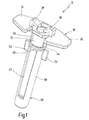
- Figs. 1 to 3 is an embodiment of an inventive Arrangement in its entirety with the reference numeral 10 denotes.
- the assembly 10 includes a syringe barrel 12 with a proximal end 14 and a distal end 16 (see FIG. 2).
- a proximal end 14 At the proximal end 14 is a back stop 18 for a in Syringe cylinder 12 arranged piston plugs 20 (FIG. 3) intended.
- Back stop 18 and piston plug 20 form in the Embodiment together a proximal closure element, which is designated in Fig. 3 in total by reference numeral 22.
- a per se known closure cap 24 is arranged. Instead, could Here, for example, but also an adapter for a needle or a needle with needle cap sit.
- the Cap at the distal end 16 of the syringe barrel 12th also have a different shape than shown here.
- the reference numeral 26 denotes a connecting element, formed pot-shaped in the present embodiment is. It encloses the syringe barrel 12 and at its distal end 16 arranged closure cap 24 and is in Area of the proximal end 14 in more detail below Way connected to the back stop 18. Form together the proximal closure element 22 (here with back stop 18 and plunger stopper 20), the distal closure element (here the Cap 24) and the connecting element 26 a tamper-evident closure for the syringe barrel 12.
- the back stop 18 is a separate in this embodiment Component that at the proximal end of the syringe barrel 12th is attached.
- the back stop 18 has a cylindrical shell-shaped Wall 28, the syringe barrel 12 in the area its proximal end 14 firmly embraces.
- One side Opening portion 30 of the wall 28 is dimensioned so that the back stop 18 in the manner of a snap connection laterally pushed onto the proximal end of the syringe barrel 12 can be.
- the back stop 18 has two laterally projecting plate portions 32, 34 having a finger rest training for the operator of the syringe.
- the shown backgauge 18 is thus intended primarily for syringe barrels, where such a finger rest not on the syringe barrel is trained. Basically, the present However, invention also applied to such syringe barrels be, with the back stop 18 then without or with accordingly modified plate areas 32, 34 is formed.
- the clear distance d between the two fishing hooks 36, 38th approximately equal to the clear inside diameter of the syringe barrel 12.
- the two catch hooks 36, 38 protrude not into a projected circular line, the inner diameter the syringe barrel 12 corresponds.
- the piston plug However, 20 radially compressed in the syringe barrel is to have a good lateral seal on the cylinder inner wall to reach the two fishing hooks 36, 38 the Nevertheless, hold piston stopper 20 reliably.
- This particular Type of training of the back stop 18 is the subject another application of the present applicant. she is but not mandatory for the realization of the present invention required, i. the present arrangement can basically also realized with other types of backgays be, as for example from the above-mentioned state known in the art.
- the connecting element 26 is in the preferred embodiment cup-shaped, wherein the syringe cylinder 12th with its distal cap 24 fit in the "pot" is stuck (Fig. 3). Deviating from this, the connecting element 26, however, for example, be formed without bottom 40, so that it is more in the form of a sleeve. Important is in this context, only that the connecting element 26 ensures that the cap 24, more generally a at the distal end 16 arranged closure element, not removed can be as long as the connecting element 26 on the Syringe cylinder 12 is seated. For this purpose, for example, one is sufficient Bordered edge, a thickening or a web, on the connecting element 26 formed in the region of the closure cap 24 are.
- the connecting element has 26 two window-like recesses 42, which are parallel to each other run, but offset by 180 ° to each other on the outer circumference of the connecting element 26 are arranged. Accordingly is the second recess 42 in the illustrations in Fig. 1 and 3 can not be seen.
- the connecting element 26 At its upper (proximal) end has the connecting element 26 a ring 44, the four thin webs 46 with the sleeve-like body 48 of the connecting element 26 is connected is.
- the webs 46 are here evenly on the outer circumference of the Distributed connecting element 26. They form predetermined breaking points, at which the connecting element 26 is broken and then the Body can be removed from the syringe barrel 12.
- the ring 44 of the connecting element 26 is located in the present Embodiment fitting in a groove 50, the distal End of the wall 28 is formed. Ring 44 and groove 50 form a snap closure, with which the connecting element 26 and the Rear stop 18 are joined together.
- the ring 44 could also be glued to the back stop 18, welded or otherwise irreversibly connected be.
- Reference numeral 52 denotes two wing-like projections, the just below the ring 44 on the connecting element 26 are formed.
- the wing-like projections 52 allow a simple rotation of the connecting element 26th relative to the back stop 18, in such a way that the webs 46th set out. Characterized in that the ring 44 in the groove 50 at the back stop 18 remains, the back stop 18 is still proximal End of the syringe barrel 12 secured, i. he can without irreversible destruction of the ring 44 can not be removed.
- connecting element 26 is not absolutely necessary.
- the connecting element 26 can also be a completely have a different shape, as long as it fulfills the intended function, namely the proximal and distal closure element (here so back stop 18 or cap 24) in their to secure respective positions.
- the connecting element 26 be a simple jetty outside the Syringe cylinder 12 from the cap 24 to the back stop 18 runs.
- the connecting element from a stiff or at least slightly stretchable material to a removal of the cap and / or the back stop 18 effectively prevent.
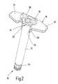
- FIGS. 1 to 3 shows the syringe barrel 12 with the back stop 18 after removal of the connecting element 26 and the closure cap 24 and after screwing a piston rod 54 in the Piston stopper 20.
- the piston rod 54 can be separated from the Arrangement 10 to be supplied to the end user. alternative it is also possible, the piston rod 54 already at the manufacturer screw in the plunger plug 20 or otherwise to attach there. For the sake of clarity, the Piston rod 54 in FIGS. 1 to 3, however, not shown.
Landscapes
- Health & Medical Sciences (AREA)
- Heart & Thoracic Surgery (AREA)
- Vascular Medicine (AREA)
- Engineering & Computer Science (AREA)
- Anesthesiology (AREA)
- Biomedical Technology (AREA)
- Hematology (AREA)
- Life Sciences & Earth Sciences (AREA)
- Animal Behavior & Ethology (AREA)
- General Health & Medical Sciences (AREA)
- Public Health (AREA)
- Veterinary Medicine (AREA)
- Diabetes (AREA)
- Infusion, Injection, And Reservoir Apparatuses (AREA)
Abstract
Description
- einem Spritzenzylinder zum Aufnehmen der Flüssigkeit, wobei der Spritzenzylinder ein proximales und ein distales Ende aufweist,
- einem proximalen Verschlusselement, das das proximale Ende des Spritzenzylinders verschließt,
- einem distalen Verschlusselement, das das distale Ende des Spritzenzylinders verschließt, und
- einem Verbindungselement, das das proximale und das distale Verschlusselement klammerartig miteinander verbindet,
- wobei zwischen den beiden Verschlusselementen und dem Verbindungselement zumindest eine Sollbruchstelle vorgesehen ist.
- Fig. 1
- ein Ausführungsbeispiel der neuen Anordnung in einer perspektivischen Darstellung,
- Fig. 2
- das Ausführungsbeispiel aus Fig. 1, jedoch ohne das dort verwendete topf- oder hülsenartige Verbindungselement,
- Fig. 3
- das Ausführungsbeispiel aus Fig. 1 in einer Querschnittsansicht, und
- Fig. 4
- eine Spritze zum Applizieren einer Flüssigkeit nach Aufbrechen des Originalitätsverschlusses aus dem Ausführungsbeispiel gemäß Fig. 1.
Claims (12)
- Anordnung zum Lagern, Transportieren und Applizieren einer vorzugsweise medizinischen Flüssigkeit (17), miteinem Spritzenzylinder (12) zum Aufnehmen der Flüssigkeit (17), wobei der Spritzenzylinder (12) ein proximales (14) und ein distales (16) Ende aufweist,einem proximalen Verschlusselement (22), das das proximale Ende (14) des Spritzenzylinders (12) verschließt,einem distalen Verschlusselement (24), das das distale Ende (16) des Spritzenzylinders (12) verschließt, undeinem Verbindungselement (26), das das proximale und das distale Verschlusselement (22, 24) klammerartig miteinander verbindet,wobei zwischen den beiden Verschlusselementen (22, 24) und dem Verbindungselement (26) zumindest eine Sollbruchstelle (46) vorgesehen ist.
- Anordnung nach Anspruch 1, dadurch gekennzeichnet, dass das proximale Verschlusselement (22) einen im Spritzenzylinder angeordneten Kolbenstopfen (20) und einen Rückanschlag (18) beinhaltet, der eine proximalseitige Entnahme des Kolbenstopfens (20) aus dem Spritzenzylinder (12) verhindert.
- Anordnung nach Anspruch 2, dadurch gekennzeichnet, dass der Rückanschlag (18) als separates Bauteil an dem proximalen Ende (14) des Spritzenzylinders (12) befestigt ist.
- Anordnung nach einem der Ansprüche 1 bis 3, dadurch gekennzeichnet, dass das distale Verschlusselement (24) und das Verbindungselement (26) einstückig miteinander verbunden sind.
- Anordnung nach einem der Ansprüche 1 bis 3, dadurch gekennzeichnet, dass das distale Verschlusselement (24) und das Verbindungselement (26) zwei getrennte Bauteile sind, wobei das Verbindungselement (26) das distale Verschlusselement (24) zumindest teilweise umgreift.
- Anordnung nach Anspruch 5, dadurch gekennzeichnet, dass das Verbindungselement (26) den Spritzenzylinder (12) hülsenartig umgibt.
- Anordnung nach Anspruch 6, dadurch gekennzeichnet, dass das Verbindungselement (26) im Bereich des Spritzenzylinders (12) zumindest eine fensterartige Ausnehmung (42) aufweist.
- Anordnung nach einem der Ansprüche 1 bis 7, dadurch gekennzeichnet, dass das Verbindungselement (26) an seiner Außenseite flügelartige Vorsprünge (52) aufweist.
- Anordnung nach einem der Ansprüche 1 bis 8, dadurch gekennzeichnet, dass das proximale Verschlusselement (22) und das Verbindungselement (26) zweistückig ausgebildet, jedoch irreversibel miteinander verbunden sind.
- Anordnung nach Anspruch 9, dadurch gekennzeichnet, dass das proximale Verschlusselement (22) und das Verbindungselement (26) formschlüssig miteinander verbunden sind.
- Anordnung nach Anspruch 9 oder 10, dadurch gekennzeichnet, dass das Verbindungselement (26) einen Ringabschnitt (44) aufweist, der den Spritzenzylinder (12) umgibt und dabei irreversibel in eine am proximalen Verschlusselement (22) ausgebildete Nut (50) eingreift.
- Originalitätsverschluss für eine vorzugsweise medizinische Spritze, mit einem proximalen Verschlusselement (22), das dazu ausgebildet ist, am proximalen Ende (14) eines Spritzenzylinders (12) angeordnet zu werden, mit einem distalen Verschlusselement (24), das dazu ausgebildet ist, am distalen Ende (16) des Spritzenzylinders (12) angeordnet zu werden, und mit einem Verbindungselement (26), das dazu ausgebildet ist, das proximale und das distale Verschlusselement (22, 24) klammerartig miteinander zu verbinden, wobei zwischen den beiden Verschlusselementen (22, 24) und dem Verbindungselement (26) zumindest eine Sollbruchstelle (46) vorgesehen ist.
Applications Claiming Priority (2)
| Application Number | Priority Date | Filing Date | Title |
|---|---|---|---|
| DE102004009918A DE102004009918B4 (de) | 2004-02-20 | 2004-02-20 | Anordnung zum Lagern, Transportieren und Applizieren einer vorzugsweise medizinischen Flüssigkeit |
| DE102004009918 | 2004-02-20 |
Publications (2)
| Publication Number | Publication Date |
|---|---|
| EP1566195A1 true EP1566195A1 (de) | 2005-08-24 |
| EP1566195B1 EP1566195B1 (de) | 2013-05-22 |
Family
ID=34706917
Family Applications (1)
| Application Number | Title | Priority Date | Filing Date |
|---|---|---|---|
| EP05001544.5A Expired - Lifetime EP1566195B1 (de) | 2004-02-20 | 2005-01-26 | Anordnung zum Lagern, Transportieren und Applizieren einer vorzugsweise medizinischen Flüssigkeit |
Country Status (3)
| Country | Link |
|---|---|
| US (1) | US20050192534A1 (de) |
| EP (1) | EP1566195B1 (de) |
| DE (1) | DE102004009918B4 (de) |
Families Citing this family (28)
| Publication number | Priority date | Publication date | Assignee | Title |
|---|---|---|---|---|
| GB0418389D0 (en) * | 2004-08-18 | 2004-09-22 | Liversidge Barry P | Injection apparatus |
| US11590286B2 (en) | 2004-11-22 | 2023-02-28 | Kaleo, Inc. | Devices, systems and methods for medicament delivery |
| US10737028B2 (en) | 2004-11-22 | 2020-08-11 | Kaleo, Inc. | Devices, systems and methods for medicament delivery |
| US7648483B2 (en) | 2004-11-22 | 2010-01-19 | Intelliject, Inc. | Devices, systems and methods for medicament delivery |
| AU2004325202B2 (en) | 2004-11-22 | 2009-02-19 | Kaleo, Inc. | Devices, systems, and methods for medicament delivery |
| DK2058020T3 (da) | 2005-02-01 | 2013-01-07 | Intelliject Inc | Indretning til indgivelse af lægemiddel |
| JP4943690B2 (ja) * | 2005-10-27 | 2012-05-30 | 前田産業株式会社 | シリンジホルダー及び注射器 |
| DE202006009628U1 (de) * | 2006-06-20 | 2007-10-31 | Ernst Mühlbauer Gmbh & Co. Kg | Spritze zum Ausbringen viskoser Flüssigkeiten oder pastenförmiger Pasten |
| JP2009240411A (ja) * | 2008-03-28 | 2009-10-22 | Terumo Corp | 医薬品容器 |
| WO2011022609A1 (en) * | 2009-08-21 | 2011-02-24 | Becton Dickinson France Sas | Tamper evident tip cap and syringe |
| US20110257605A1 (en) * | 2010-04-16 | 2011-10-20 | Kloehn, Inc. | Self-centering syringe assembly and centering syringe plunger guide |
| US20120046411A1 (en) | 2010-08-20 | 2012-02-23 | Becton, Dickinson And Company | Recycled Resin Compositions And Disposable Medical Devices Made Therefrom |
| US9173999B2 (en) * | 2011-01-26 | 2015-11-03 | Kaleo, Inc. | Devices and methods for delivering medicaments from a multi-chamber container |
| US8939943B2 (en) | 2011-01-26 | 2015-01-27 | Kaleo, Inc. | Medicament delivery device for administration of opioid antagonists including formulations for naloxone |
| US8657793B2 (en) | 2011-09-30 | 2014-02-25 | Becton Dickinson France, S.A.S | Space saving plunger cap and rod assembly |
| USD667109S1 (en) | 2011-11-04 | 2012-09-11 | Becton, Dickinson And Company | Syringe plunger rod |
| USD673675S1 (en) | 2011-11-04 | 2013-01-01 | Becton, Dickinson And Company | Syringe plunger rod |
| USD667108S1 (en) | 2011-11-04 | 2012-09-11 | Becton, Dickinson And Company | Syringe plunger rod |
| USD673268S1 (en) | 2011-11-04 | 2012-12-25 | Becton, Dickinson And Company | Syringe plunger rod |
| US20130116628A1 (en) | 2011-11-04 | 2013-05-09 | Becton, Dickinson And Company | Recycled Resin Compositions And Disposable Medical Devices Made Therefrom |
| USD713028S1 (en) | 2011-11-04 | 2014-09-09 | Becton, Dickinson And Company | Syringe plunger rod |
| USD667107S1 (en) | 2011-11-04 | 2012-09-11 | Becton, Dickinson And Company | Syringe plunger rod |
| US20160144122A1 (en) * | 2014-11-26 | 2016-05-26 | Fisher Clinical Services GmbH | Syringe Assembly with Plunger Rod Backstop and Method of Use |
| AU2016287571C1 (en) | 2015-06-30 | 2021-12-23 | Kaleo, Inc. | Auto-injectors for administration of a medicament within a prefilled syringe |
| EP3902584A4 (de) | 2018-12-29 | 2022-09-07 | Kaleo, Inc. | Vorrichtungen und verfahren zur abgabe von substanzen in einer vorgefüllten spritze |
| US11167087B2 (en) | 2019-08-09 | 2021-11-09 | Kaleo, Inc. | Devices and methods for delivery of substances within a prefilled syringe |
| US12268847B1 (en) | 2021-02-10 | 2025-04-08 | Kaleo, Inc. | Devices and methods for delivery of substances within a medicament container |
| WO2022171535A1 (en) * | 2021-02-15 | 2022-08-18 | Shl Medical Ag | Syringe carriers |
Citations (5)
| Publication number | Priority date | Publication date | Assignee | Title |
|---|---|---|---|---|
| US3811441A (en) * | 1972-02-10 | 1974-05-21 | Survival Technology | Cartridge syringe |
| EP0645152A2 (de) * | 1993-09-29 | 1995-03-29 | Sterling Winthrop Inc. | Einweghalter für vorgefüllte Kartuschennadel Einheit |
| US5817064A (en) * | 1995-10-23 | 1998-10-06 | American Home Products Corporation | Syringe needle guard |
| US5876379A (en) * | 1998-01-22 | 1999-03-02 | Alcon Laboratories, Inc. | Syringe cannula holder |
| US20030220615A1 (en) * | 2002-05-04 | 2003-11-27 | Arthur Fabian | Syringe, especially a pre-filled one-time-use syringe with a securely attachable finger rest |
Family Cites Families (7)
| Publication number | Priority date | Publication date | Assignee | Title |
|---|---|---|---|---|
| US4540405A (en) * | 1983-07-12 | 1985-09-10 | Cilco, Inc. | Disposable syringe sleeve |
| US4643724A (en) * | 1985-12-16 | 1987-02-17 | Alcon Laboratories, Inc. | Syringe holder |
| US5667495A (en) * | 1995-04-21 | 1997-09-16 | Becton Dickinson France S.A. | Backstop device for a syringe |
| US5607399A (en) * | 1995-09-22 | 1997-03-04 | Becton, Dickinson And Company | Backstop device for a flangeless syringe |
| FR2799376B1 (fr) * | 1999-10-07 | 2002-01-18 | Marc Brunel | Dispositif d'injection a usage unique |
| US6382204B1 (en) * | 1999-10-14 | 2002-05-07 | Becton Dickinson And Company | Drug delivery system including holder and drug container |
| DE10247965A1 (de) * | 2002-10-15 | 2004-05-06 | Transcoject Gesellschaft für medizinische Geräte mbH & Co KG | Originalitätsverschluss für eine Spritze |
-
2004
- 2004-02-20 DE DE102004009918A patent/DE102004009918B4/de not_active Expired - Fee Related
-
2005
- 2005-01-26 EP EP05001544.5A patent/EP1566195B1/de not_active Expired - Lifetime
- 2005-02-18 US US11/062,347 patent/US20050192534A1/en not_active Abandoned
Patent Citations (5)
| Publication number | Priority date | Publication date | Assignee | Title |
|---|---|---|---|---|
| US3811441A (en) * | 1972-02-10 | 1974-05-21 | Survival Technology | Cartridge syringe |
| EP0645152A2 (de) * | 1993-09-29 | 1995-03-29 | Sterling Winthrop Inc. | Einweghalter für vorgefüllte Kartuschennadel Einheit |
| US5817064A (en) * | 1995-10-23 | 1998-10-06 | American Home Products Corporation | Syringe needle guard |
| US5876379A (en) * | 1998-01-22 | 1999-03-02 | Alcon Laboratories, Inc. | Syringe cannula holder |
| US20030220615A1 (en) * | 2002-05-04 | 2003-11-27 | Arthur Fabian | Syringe, especially a pre-filled one-time-use syringe with a securely attachable finger rest |
Also Published As
| Publication number | Publication date |
|---|---|
| DE102004009918B4 (de) | 2007-03-01 |
| EP1566195B1 (de) | 2013-05-22 |
| DE102004009918A1 (de) | 2005-11-10 |
| US20050192534A1 (en) | 2005-09-01 |
Similar Documents
| Publication | Publication Date | Title |
|---|---|---|
| EP1566195B1 (de) | Anordnung zum Lagern, Transportieren und Applizieren einer vorzugsweise medizinischen Flüssigkeit | |
| DE4434644C2 (de) | Behältnis zur Lagerung und Verabreichung von Injektions-, Infusions- und Diagnostikpräparaten | |
| DE69622949T2 (de) | Eine Arretiervorrichtung für eine Spritze | |
| DE69726531T2 (de) | Verriegelbare Schutzhülse für vorgefüllte Spritze | |
| DE69724537T2 (de) | Verbesserte Phiolenverbindung für einen Arzneimittelbehälter | |
| DE69726530T2 (de) | Abdichtende Schutzbarriere für eine Spritze | |
| DE69723633T2 (de) | Übertragungsvorrichtung mit einem spritzlosen Ventil für Arzneimittelbehälter | |
| DE102004009919B4 (de) | Spritze, insbesondere für medizinische Anwendungen | |
| DE69816965T2 (de) | Verriegelbare schutzschildanordnung für eine vorfüllbare spritze | |
| DE60019446T2 (de) | Flüssigkeitstransferset für phiolen und andere medizinische behälter | |
| DE4323124B4 (de) | Spritze mit Zwei-Komponenten-Zylinder | |
| DE2909002C3 (de) | Injektionsspritze für einmalige Verwendung | |
| DE69703889T2 (de) | Kombination eines behälters mit einem abreissverschluss, und verfahren zur herstellung derselben | |
| DE10247965A1 (de) | Originalitätsverschluss für eine Spritze | |
| WO2007093307A1 (de) | Spritze | |
| DE69603597T2 (de) | Vorgefüllte sicherheitsspritze | |
| DE212009000058U1 (de) | Sicherheitsspritze | |
| EP1484072A1 (de) | Spritze sowie Verfahren zum Herstellen einer solchen | |
| EP3002021B1 (de) | Stopfen zum aufsetzen auf ein anschlusselement einer medizinischen spritze | |
| DE69913324T2 (de) | Einwegspritze | |
| EP1136091A1 (de) | Kanüle | |
| DE1063341B (de) | Injektionsspritze | |
| DE2715093A1 (de) | Kompakte injektionsspritze | |
| WO2010075920A1 (de) | Karpulenspritze mit einer injektionskanüle und einer durchstechkanüle | |
| DE20121260U1 (de) | Kanüle |
Legal Events
| Date | Code | Title | Description |
|---|---|---|---|
| PUAI | Public reference made under article 153(3) epc to a published international application that has entered the european phase |
Free format text: ORIGINAL CODE: 0009012 |
|
| AK | Designated contracting states |
Kind code of ref document: A1 Designated state(s): AT BE BG CH CY CZ DE DK EE ES FI FR GB GR HU IE IS IT LI LT LU MC NL PL PT RO SE SI SK TR |
|
| AX | Request for extension of the european patent |
Extension state: AL BA HR LV MK YU |
|
| 17P | Request for examination filed |
Effective date: 20060201 |
|
| AKX | Designation fees paid |
Designated state(s): AT BE BG CH CY CZ DE DK EE ES FI FR GB GR HU IE IS IT LI LT LU MC NL PL PT RO SE SI SK TR |
|
| 17Q | First examination report despatched |
Effective date: 20100604 |
|
| REG | Reference to a national code |
Ref country code: DE Ref legal event code: R079 Ref document number: 502005013717 Country of ref document: DE Free format text: PREVIOUS MAIN CLASS: A61M0005500000 Ipc: A61M0005000000 |
|
| GRAP | Despatch of communication of intention to grant a patent |
Free format text: ORIGINAL CODE: EPIDOSNIGR1 |
|
| RIC1 | Information provided on ipc code assigned before grant |
Ipc: A61M 5/50 20060101ALI20121106BHEP Ipc: A61M 5/00 20060101AFI20121106BHEP |
|
| GRAS | Grant fee paid |
Free format text: ORIGINAL CODE: EPIDOSNIGR3 |
|
| GRAA | (expected) grant |
Free format text: ORIGINAL CODE: 0009210 |
|
| AK | Designated contracting states |
Kind code of ref document: B1 Designated state(s): AT BE BG CH CY CZ DE DK EE ES FI FR GB GR HU IE IS IT LI LT LU MC NL PL PT RO SE SI SK TR |
|
| REG | Reference to a national code |
Ref country code: GB Ref legal event code: FG4D Free format text: NOT ENGLISH |
|
| REG | Reference to a national code |
Ref country code: CH Ref legal event code: EP |
|
| REG | Reference to a national code |
Ref country code: CH Ref legal event code: NV Representative=s name: BOVARD AG, CH |
|
| REG | Reference to a national code |
Ref country code: AT Ref legal event code: REF Ref document number: 612862 Country of ref document: AT Kind code of ref document: T Effective date: 20130615 |
|
| REG | Reference to a national code |
Ref country code: IE Ref legal event code: FG4D Free format text: LANGUAGE OF EP DOCUMENT: GERMAN |
|
| REG | Reference to a national code |
Ref country code: DE Ref legal event code: R096 Ref document number: 502005013717 Country of ref document: DE Effective date: 20130718 |
|
| REG | Reference to a national code |
Ref country code: LT Ref legal event code: MG4D |
|
| PG25 | Lapsed in a contracting state [announced via postgrant information from national office to epo] |
Ref country code: FI Free format text: LAPSE BECAUSE OF FAILURE TO SUBMIT A TRANSLATION OF THE DESCRIPTION OR TO PAY THE FEE WITHIN THE PRESCRIBED TIME-LIMIT Effective date: 20130522 Ref country code: GR Free format text: LAPSE BECAUSE OF FAILURE TO SUBMIT A TRANSLATION OF THE DESCRIPTION OR TO PAY THE FEE WITHIN THE PRESCRIBED TIME-LIMIT Effective date: 20130823 Ref country code: SI Free format text: LAPSE BECAUSE OF FAILURE TO SUBMIT A TRANSLATION OF THE DESCRIPTION OR TO PAY THE FEE WITHIN THE PRESCRIBED TIME-LIMIT Effective date: 20130522 Ref country code: LT Free format text: LAPSE BECAUSE OF FAILURE TO SUBMIT A TRANSLATION OF THE DESCRIPTION OR TO PAY THE FEE WITHIN THE PRESCRIBED TIME-LIMIT Effective date: 20130522 Ref country code: ES Free format text: LAPSE BECAUSE OF FAILURE TO SUBMIT A TRANSLATION OF THE DESCRIPTION OR TO PAY THE FEE WITHIN THE PRESCRIBED TIME-LIMIT Effective date: 20130902 Ref country code: SE Free format text: LAPSE BECAUSE OF FAILURE TO SUBMIT A TRANSLATION OF THE DESCRIPTION OR TO PAY THE FEE WITHIN THE PRESCRIBED TIME-LIMIT Effective date: 20130522 Ref country code: IS Free format text: LAPSE BECAUSE OF FAILURE TO SUBMIT A TRANSLATION OF THE DESCRIPTION OR TO PAY THE FEE WITHIN THE PRESCRIBED TIME-LIMIT Effective date: 20130922 Ref country code: PT Free format text: LAPSE BECAUSE OF FAILURE TO SUBMIT A TRANSLATION OF THE DESCRIPTION OR TO PAY THE FEE WITHIN THE PRESCRIBED TIME-LIMIT Effective date: 20130923 |
|
| REG | Reference to a national code |
Ref country code: NL Ref legal event code: VDEP Effective date: 20130522 |
|
| PG25 | Lapsed in a contracting state [announced via postgrant information from national office to epo] |
Ref country code: BG Free format text: LAPSE BECAUSE OF FAILURE TO SUBMIT A TRANSLATION OF THE DESCRIPTION OR TO PAY THE FEE WITHIN THE PRESCRIBED TIME-LIMIT Effective date: 20130822 Ref country code: PL Free format text: LAPSE BECAUSE OF FAILURE TO SUBMIT A TRANSLATION OF THE DESCRIPTION OR TO PAY THE FEE WITHIN THE PRESCRIBED TIME-LIMIT Effective date: 20130522 |
|
| PG25 | Lapsed in a contracting state [announced via postgrant information from national office to epo] |
Ref country code: DK Free format text: LAPSE BECAUSE OF FAILURE TO SUBMIT A TRANSLATION OF THE DESCRIPTION OR TO PAY THE FEE WITHIN THE PRESCRIBED TIME-LIMIT Effective date: 20130522 Ref country code: EE Free format text: LAPSE BECAUSE OF FAILURE TO SUBMIT A TRANSLATION OF THE DESCRIPTION OR TO PAY THE FEE WITHIN THE PRESCRIBED TIME-LIMIT Effective date: 20130522 Ref country code: CZ Free format text: LAPSE BECAUSE OF FAILURE TO SUBMIT A TRANSLATION OF THE DESCRIPTION OR TO PAY THE FEE WITHIN THE PRESCRIBED TIME-LIMIT Effective date: 20130522 Ref country code: SK Free format text: LAPSE BECAUSE OF FAILURE TO SUBMIT A TRANSLATION OF THE DESCRIPTION OR TO PAY THE FEE WITHIN THE PRESCRIBED TIME-LIMIT Effective date: 20130522 |
|
| PG25 | Lapsed in a contracting state [announced via postgrant information from national office to epo] |
Ref country code: NL Free format text: LAPSE BECAUSE OF FAILURE TO SUBMIT A TRANSLATION OF THE DESCRIPTION OR TO PAY THE FEE WITHIN THE PRESCRIBED TIME-LIMIT Effective date: 20130522 Ref country code: RO Free format text: LAPSE BECAUSE OF FAILURE TO SUBMIT A TRANSLATION OF THE DESCRIPTION OR TO PAY THE FEE WITHIN THE PRESCRIBED TIME-LIMIT Effective date: 20130522 |
|
| PLBE | No opposition filed within time limit |
Free format text: ORIGINAL CODE: 0009261 |
|
| STAA | Information on the status of an ep patent application or granted ep patent |
Free format text: STATUS: NO OPPOSITION FILED WITHIN TIME LIMIT |
|
| 26N | No opposition filed |
Effective date: 20140225 |
|
| REG | Reference to a national code |
Ref country code: DE Ref legal event code: R097 Ref document number: 502005013717 Country of ref document: DE Effective date: 20140225 |
|
| PG25 | Lapsed in a contracting state [announced via postgrant information from national office to epo] |
Ref country code: MC Free format text: LAPSE BECAUSE OF FAILURE TO SUBMIT A TRANSLATION OF THE DESCRIPTION OR TO PAY THE FEE WITHIN THE PRESCRIBED TIME-LIMIT Effective date: 20130522 Ref country code: LU Free format text: LAPSE BECAUSE OF FAILURE TO SUBMIT A TRANSLATION OF THE DESCRIPTION OR TO PAY THE FEE WITHIN THE PRESCRIBED TIME-LIMIT Effective date: 20140126 |
|
| GBPC | Gb: european patent ceased through non-payment of renewal fee |
Effective date: 20140126 |
|
| REG | Reference to a national code |
Ref country code: IE Ref legal event code: MM4A |
|
| PG25 | Lapsed in a contracting state [announced via postgrant information from national office to epo] |
Ref country code: GB Free format text: LAPSE BECAUSE OF NON-PAYMENT OF DUE FEES Effective date: 20140126 |
|
| PG25 | Lapsed in a contracting state [announced via postgrant information from national office to epo] |
Ref country code: IE Free format text: LAPSE BECAUSE OF NON-PAYMENT OF DUE FEES Effective date: 20140126 |
|
| REG | Reference to a national code |
Ref country code: AT Ref legal event code: MM01 Ref document number: 612862 Country of ref document: AT Kind code of ref document: T Effective date: 20140126 |
|
| PG25 | Lapsed in a contracting state [announced via postgrant information from national office to epo] |
Ref country code: AT Free format text: LAPSE BECAUSE OF NON-PAYMENT OF DUE FEES Effective date: 20140126 |
|
| REG | Reference to a national code |
Ref country code: FR Ref legal event code: PLFP Year of fee payment: 12 |
|
| PGFP | Annual fee paid to national office [announced via postgrant information from national office to epo] |
Ref country code: CH Payment date: 20160120 Year of fee payment: 12 Ref country code: IT Payment date: 20160127 Year of fee payment: 12 Ref country code: DE Payment date: 20160120 Year of fee payment: 12 |
|
| PGFP | Annual fee paid to national office [announced via postgrant information from national office to epo] |
Ref country code: BE Payment date: 20160120 Year of fee payment: 12 Ref country code: FR Payment date: 20160121 Year of fee payment: 12 |
|
| PG25 | Lapsed in a contracting state [announced via postgrant information from national office to epo] |
Ref country code: CY Free format text: LAPSE BECAUSE OF FAILURE TO SUBMIT A TRANSLATION OF THE DESCRIPTION OR TO PAY THE FEE WITHIN THE PRESCRIBED TIME-LIMIT Effective date: 20130522 |
|
| PG25 | Lapsed in a contracting state [announced via postgrant information from national office to epo] |
Ref country code: HU Free format text: LAPSE BECAUSE OF FAILURE TO SUBMIT A TRANSLATION OF THE DESCRIPTION OR TO PAY THE FEE WITHIN THE PRESCRIBED TIME-LIMIT; INVALID AB INITIO Effective date: 20050126 Ref country code: TR Free format text: LAPSE BECAUSE OF FAILURE TO SUBMIT A TRANSLATION OF THE DESCRIPTION OR TO PAY THE FEE WITHIN THE PRESCRIBED TIME-LIMIT Effective date: 20130522 |
|
| PG25 | Lapsed in a contracting state [announced via postgrant information from national office to epo] |
Ref country code: BE Free format text: LAPSE BECAUSE OF NON-PAYMENT OF DUE FEES Effective date: 20170131 |
|
| REG | Reference to a national code |
Ref country code: DE Ref legal event code: R119 Ref document number: 502005013717 Country of ref document: DE |
|
| REG | Reference to a national code |
Ref country code: CH Ref legal event code: PL |
|
| REG | Reference to a national code |
Ref country code: FR Ref legal event code: ST Effective date: 20170929 |
|
| PG25 | Lapsed in a contracting state [announced via postgrant information from national office to epo] |
Ref country code: CH Free format text: LAPSE BECAUSE OF NON-PAYMENT OF DUE FEES Effective date: 20170131 Ref country code: FR Free format text: LAPSE BECAUSE OF NON-PAYMENT OF DUE FEES Effective date: 20170131 Ref country code: LI Free format text: LAPSE BECAUSE OF NON-PAYMENT OF DUE FEES Effective date: 20170131 |
|
| PG25 | Lapsed in a contracting state [announced via postgrant information from national office to epo] |
Ref country code: DE Free format text: LAPSE BECAUSE OF NON-PAYMENT OF DUE FEES Effective date: 20170801 |
|
| REG | Reference to a national code |
Ref country code: BE Ref legal event code: MM Effective date: 20170131 |
|
| PG25 | Lapsed in a contracting state [announced via postgrant information from national office to epo] |
Ref country code: IT Free format text: LAPSE BECAUSE OF NON-PAYMENT OF DUE FEES Effective date: 20170126 |