EP1566129A2 - Electric household appliance for food processing - Google Patents
Electric household appliance for food processing Download PDFInfo
- Publication number
- EP1566129A2 EP1566129A2 EP05356025A EP05356025A EP1566129A2 EP 1566129 A2 EP1566129 A2 EP 1566129A2 EP 05356025 A EP05356025 A EP 05356025A EP 05356025 A EP05356025 A EP 05356025A EP 1566129 A2 EP1566129 A2 EP 1566129A2
- Authority
- EP
- European Patent Office
- Prior art keywords
- safety rod
- lid
- safety
- rod
- cover
- Prior art date
- Legal status (The legal status is an assumption and is not a legal conclusion. Google has not performed a legal analysis and makes no representation as to the accuracy of the status listed.)
- Granted
Links
Images


Classifications
-
- A—HUMAN NECESSITIES
- A47—FURNITURE; DOMESTIC ARTICLES OR APPLIANCES; COFFEE MILLS; SPICE MILLS; SUCTION CLEANERS IN GENERAL
- A47J—KITCHEN EQUIPMENT; COFFEE MILLS; SPICE MILLS; APPARATUS FOR MAKING BEVERAGES
- A47J43/00—Implements for preparing or holding food, not provided for in other groups of this subclass
- A47J43/04—Machines for domestic use not covered elsewhere, e.g. for grinding, mixing, stirring, kneading, emulsifying, whipping or beating foodstuffs, e.g. power-driven
- A47J43/07—Parts or details, e.g. mixing tools, whipping tools
- A47J43/075—Safety devices
- A47J43/0761—Safety devices for machines with tools driven from the lower side
- A47J43/0772—Safety devices for machines with tools driven from the lower side activated by the proper positioning of the cover
Abstract
Description
La présente invention concerne le domaine technique général des appareils électroménagers de préparation culinaire tels que notamment les robots ménager multifonctions. La présente invention est relative à un appareil comportant un socle sur lequel repose un récipient de travail et un caisson adjacent au récipient de travail, le récipient comportant un couvercle amovible muni d'une patte qui s'insère par rotation dans une fente du caisson et se rapporte plus particulièrement aux moyens de verrouillage du couvercle sur le caisson.The present invention relates to the general technical field of apparatus appliances for culinary preparation such as, in particular, robots household multifunction. The present invention relates to a device having a base on which a work container and a box rest adjacent to the working container, the container having a removable lid provided with a tab which rotates into a slot in the box and more particularly relates to the locking means of the lid on the caisson.
On connaít, du document EP 025 972, un robot ménager comportant un bol de travail coiffé par un couvercle amovible et un moteur entraínant un outil rotatif monté dans le fond du récipient de travail, le moteur étant mis en route par l'utilisateur au moyen d'un bouton de commande. Le robot comporte également un caisson adjacent au récipient de travail comprenant un verrou de sécurité monté mobile qui coopère avec une patte du couvercle pour immobiliser le couvercle et n'autoriser l'actionnement du bouton de commande du moteur que lorsque le couvercle est immobilisé. Le robot comporte également un bouton de déverrouillage qui agit sur le verrou de sécurité pour libérer le couvercle.Document EP 025 972 discloses a food processor comprising a bowl of work capped by a removable cover and a motor driving a rotary tool mounted in the bottom of the working container, the engine being started by the user by means of a command button. The robot also features a box adjacent to the work container comprising a safety lock movably mounted which cooperates with a tab of the cover to immobilize the cover and only allow the operation of the engine control knob when the lid is immobilized. The robot also has a button unlocking that acts on the security lock to release the lid.
Un tel dispositif de verrouillage du couvercle présente cependant l'inconvénient d'être relativement encombrant, en particulier verticalement, et d'imposer une disposition des boutons de commande du moteur et de déverrouillage du couvercle sur deux faces différentes du caisson, ce qui conduit souvent à avoir l'un des boutons visuellement caché par le corps de l'appareil.However, such a device for locking the lid has the disadvantage to be relatively bulky, especially vertically, and to impose a arrangement of the motor control and unlocking buttons of the cover on two different sides of the box, which often leads to one of the buttons visually hidden by the body of the device.
L'invention qui suit vise à pallier ces inconvénients en proposant notamment un appareil électroménager dans lequel le dispositif de sécurité, assurant le verrouillage du couvercle et le blocage du bouton de commande du moteur lorsque le couvercle n'est pas verrouillé, est d'une grande compacité et utilise un nombre réduit de pièces. Un autre but de la présente invention est de proposer un appareil électroménager dans lequel le dispositif de sécurité permet un regroupement du bouton de commande du moteur et du bouton de déverrouillage du couvercle sur une même face de l'appareil.The following invention aims to overcome these disadvantages by proposing in particular a appliance in which the safety device, ensuring the locking the lid and locking the engine control knob when the lid is not locked, is very compact and uses a reduced number of pieces. Another object of the present invention is to propose an appliance in which the safety device allows grouping of the engine control button and the button Unlocking the lid on the same side of the device.
Le but de l'invention est atteint par un appareil électroménager de préparation culinaire comportant un boítier comprenant un socle sur lequel repose un récipient de travail et un caisson adjacent au récipient, le boítier comportant un moteur entraínant un outil rotatif dont le fonctionnement est géré au moyen d'un bouton de commande, le récipient de travail comportant un couvercle amovible, du type à verrouillage par rotation, muni d'une patte de verrouillage s'insérant dans une fente pratiquée dans le caisson pour coopérer avec un dispositif de sécurité assurant le verrouillage du couvercle et empêchant l'actionnement du bouton de commande lorsque le couvercle n'est pas verrouillé, le déverrouillage du couvercle s'effectuant par l'actionnement d'un bouton de déverrouillage, caractérisé en ce que le dispositif de sécurité comporte une tige de sécurité dont une extrémité vient au contact avec la patte de verrouillage lors de la fermeture du couvercle, la tige de sécurité se déplaçant suivant un mouvement de rotation et de translation lors de la rotation du couvercle en vue de son verrouillage et en ce que le bouton de commande du moteur et le bouton de déverrouillage du couvercle sont regroupés sur une même face de l'appareil.The object of the invention is achieved by a household appliance preparation food processor comprising a housing comprising a base on which a container and a box adjacent to the container, the housing having a motor driving a rotary tool whose operation is managed by means of a control button, the working container having a removable cover, of the rotation locking type, provided with a locking tab inserting in a slot in the box to cooperate with a device security ensuring the locking of the lid and preventing the actuation of the control button when the lid is not locked, unlocking of the lid being effected by the actuation of an unlocking button, characterized in that the safety device comprises a safety rod of which one end comes into contact with the locking tab when closing of the cover, the safety rod moving in a rotational movement and translation during the rotation of the cover for locking and in what the engine control knob and the unlock button the cover are grouped on the same side of the device.
Une telle caractéristique présente l'avantage d'offrir un dispositif de sécurité compact et avec un nombre de pièces limité ainsi qu'une bonne ergonomie d'utilisation des boutons.Such a characteristic has the advantage of offering a safety device compact and with a limited number of parts as well as good ergonomics button usage.
Selon une autre caractéristique de l'invention, le bouton de commande du moteur et le bouton de déverrouillage sont concentriques et sont disposés sur le caisson à proximité de la tige de sécurité.According to another characteristic of the invention, the control button of the engine and the unlock button are concentric and are arranged on the box near the safety rod.
Cette caractéristique permet d'améliorer encore l'ergonomie des boutons de commande et de déverrouillage.This characteristic makes it possible to further improve the ergonomics of the buttons of control and unlocking.
Selon une autre caractéristique de l'invention, le bouton de commande du moteur entoure le bouton de déverrouillage, le bouton de commande du moteur étant du type rotatif et le bouton de déverrouillage étant du type poussoir.According to another characteristic of the invention, the engine control knob surrounds the release button, the engine control knob being rotary type and the unlocking button being of the push type.
Selon une autre caractéristique de l'invention, le bouton de déverrouillage occupe deux positions d'enfoncement distinctes en fonction de l'état du verrouillage de la tige de sécurité. According to another characteristic of the invention, the unlocking button occupies two distinct driving positions according to the state of the lock of the safety rod.
Une telle caractéristique présente l'avantage de permettre l'identification visuelle de l'état de verrouillage du dispositif de sécurité.Such a characteristic has the advantage of allowing identification visual of the lock state of the safety device.
Selon encore une autre caractéristique de l'invention, la tige de sécurité est montée pivotante autour d'un axe pouvant se déplacer en translation au travers d'un logement réalisé sur une platine support.According to yet another characteristic of the invention, the safety rod is pivotally mounted around an axis that can move in translation through a housing made on a support plate.
Une telle caractéristique permet d'obtenir simplement une liaison autorisant le basculement et la translation de la tige de sécurité.Such a feature makes it possible to simply obtain a link allowing the tilting and translation of the safety rod.
Selon encore une autre caractéristique de l'invention, l'axe de pivotement de la tige de sécurité est incliné par rapport au plan de rotation du couvercle.According to yet another characteristic of the invention, the pivot axis of the safety rod is inclined relative to the plane of rotation of the lid.
Une telle caractéristique permet d'obtenir une orientation des boutons de commande du moteur et du déverrouillage du couvercle vers l'avant de l'appareil.Such a characteristic makes it possible to obtain an orientation of the buttons of motor control and unlocking the cover towards the front of the device.
Selon une autre caractéristique de l'invention, l'extrémité de la tige de sécurité comporte une rampe de guidage de telle sorte que l'appui de la patte du couvercle sur la rampe de guidage provoque le mouvement de pivotement de la tige de sécurité.According to another characteristic of the invention, the end of the safety rod has a guide ramp so that the support of the leg of the cover on the guide ramp causes the pivoting movement of the safety rod.
Selon encore une autre caractéristique de l'invention, l'extrémité de la tige de sécurité comporte une cavité dans laquelle s'insère l'extrémité de la patte de verrouillage lorsque la tige de sécurité est déplacée radialement au couvercle et en direction de la patte de verrouillage du couvercle, sous l'effet de moyens de rappel, au cours de l'opération de verrouillage du couvercle.According to yet another characteristic of the invention, the end of the stem of safety device has a cavity into which the end of the locking when the safety rod is moved radially to the lid and in the direction of the locking tab of the lid, under the effect of means during the locking operation of the lid.
Une telle caractéristique permet une immobilisation simple et fiable du couvercle sur le caisson.Such a characteristic allows a simple and reliable immobilization of the lid on the box.
Selon encore une autre caractéristique de l'invention, les moyens de rappel sont constitués par un ressort porté par l'extrémité de la tige opposée au couvercle et le ressort prend appui sur un plan incliné de la platine support de sorte que le pivotement de la tige de sécurité lors du verrouillage du couvercle provoque la compression du ressort.According to yet another characteristic of the invention, the return means are constituted by a spring carried by the end of the rod opposite to the lid and the spring is supported on an inclined plane of the support plate so that the pivoting of the safety rod when locking the cover causes the compression of the spring.
Selon encore une autre caractéristique de l'invention, le mouvement de translation de la tige de sécurité s'effectue successivement à son mouvement de pivotement, la platine support comportant un crochet de verrouillage sur lequel vient buter une paroi de la tige de sécurité avant le pivotement complet de cette dernière, empêchant ainsi la translation de la tige de sécurité dans une première phase du mouvement de la tige, tandis qu'une fois le pivotement de la tige de sécurité effectué, la paroi de la tige de sécurité s'insère par translation sous le crochet de verrouillage empêchant ainsi tout mouvement de pivotement de la tige de sécurité.According to yet another characteristic of the invention, the movement of translation of the safety rod is effected successively to its movement of pivoting, the support plate having a locking hook on which abuts a wall of the safety rod before the complete pivoting of this last, thus preventing the translation of the safety rod into a first phase of the rod movement, while once the pivot of the rod of safety carried out, the wall of the safety rod is inserted by translation under the locking hook thus preventing any pivoting movement of the rod of security.
Selon une autre caractéristique de l'invention, le bouton de déverrouillage comporte une surface inclinée venant au contact de la tige de sécurité qui provoque le déplacement de la tige de sécurité à l'encontre des moyens de rappel lorsque l'on appuie sur le bouton de déverrouillage.According to another characteristic of the invention, the unlocking button has an inclined surface coming into contact with the safety rod which causes the safety rod to move against the means of recall when the unlock button is pressed.
Une telle caractéristique procure un moyen simple pour déplacer la tige de sécurité en vue du déverrouillage du couvercle.Such a feature provides a simple way to move the rod of security to unlock the lid.
Selon une autre caractéristique de l'invention, le corps de la tige de sécurité s'oppose à l'actionnement du bouton de commande du moteur lorsque la tige de sécurité est dans la position correspondant à la position déverrouillée du couvercle.According to another characteristic of the invention, the body of the safety rod opposes the actuation of the engine control button when the rod of security is in the position corresponding to the unlocked position of the lid.
Selon une autre caractéristique de l'invention, le bouton de commande est lié en rotation à une couronne et la couronne comporte une partie interférant avec le corps de la tige de sécurité pour empêcher la rotation du bouton de commande lorsque la tige de sécurité est dans la position déverrouillée.According to another characteristic of the invention, the control button is linked in rotation to a crown and the crown has a part interfering with the body of the safety rod to prevent rotation of the control knob when the safety rod is in the unlocked position.
Selon une autre caractéristique de l'invention, la tige de sécurité comporte des ouvertures venant en regard de ladite partie de la couronne lorsque la tige de sécurité est dans la position verrouillée de sorte que le bouton de commande puisse être tourné.According to another characteristic of the invention, the safety rod comprises openings facing said part of the crown when the rod of security is in the locked position so the command button can be turned.
On comprendra mieux les buts, aspects et avantages de la présente invention, d'après la description donnée ci-après d'un mode particulier de réalisation de l'invention présenté à titre d'exemple non limitatif, en se référant aux dessins annexés dans lesquels :
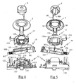
- la figure 1 est une vue générale, en perspective, de la face avant d'un robot selon un mode de réalisation particulier de l'invention ;
- la figure 2 est une vue en perspective de la face arrière du robot de la figure 1 ;
- la figure 3 est une vue similaire à la figure 1 dans laquelle le boítier du robot est partiellement arraché de manière à laisser apparaítre le dispositif de sécurité du robot assurant le verrouillage du couvercle ;
- la figure 4 est une vue de face, éclatée, du dispositif de sécurité du robot de la figure 1 ;
- la figure 5 est une vue de dos, éclatée, du dispositif de sécurité du robot de la figure 1 ;
- la figure 6 est une vue de face, agrandie, de la platine supportant le bouton de commande du moteur, le bouton de déverrouillage du couvercle et le dispositif de sécurité du robot assurant le verrouillage du couvercle, l'ensemble étant représenté dans une position correspondant au couvercle non verrouillé ;
- la figure 7 est une vue de côté de la platine de la figure 6 représentée seule ;
- la figure 8 est une vue de l'autre côté de la platine représentée à la figure 7 ;
- la figure 9 est une vue en perspective de la platine supportant le dispositif de sécurité du robot, sans le bouton de commande du moteur ni le bouton de déverrouillage, dans la position correspondant au couvercle déverrouillé ;
- la figure 10 est une vue de dessus de la platine de la figure 6 ; ,
- la figure 11 est une vue en coupe suivant la ligne XI-XI de la figure 7 ;
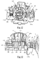
- la figure 12 est une vue similaire à la figure 9 lorsque le dispositif de sécurité est dans la position correspondant au couvercle verrouillé ;
- la figure 13 est une vue similaire à la figure 11 représentant le dispositif de sécurité du robot dans la position correspondant au couvercle verrouillé ;
- la figure 14 est une vue en perspective d'un côté de la platine avec le dispositif de sécurité en position couvercle verrouillé et le bouton de commande du moteur tourné de quelques degrés dans le sens anti-horaire pour la mise en marche continue du moteur du robot ;
- la figure 15 est une vue en perspective de l'autre côté de la platine avec le dispositif de sécurité en position couvercle verrouillé et le bouton de commande tourné de quelques degrés dans le sens horaire pour la mise en marche du moteur par impulsion.
- Figure 1 is a general perspective view of the front face of a robot according to a particular embodiment of the invention;
- Figure 2 is a perspective view of the rear face of the robot of Figure 1;
- Figure 3 is a view similar to Figure 1 in which the housing of the robot is partially torn so as to reveal the safety device of the robot ensuring the locking of the lid;
- Figure 4 is an exploded front view of the safety device of the robot of Figure 1;
- Figure 5 is an exploded rear view of the safety device of the robot of Figure 1;
- FIG. 6 is a front view, enlarged, of the plate supporting the engine control button, the cover release button and the safety device of the robot ensuring the locking of the cover, the assembly being represented in a corresponding position. unlatched lid;
- Figure 7 is a side view of the plate of Figure 6 shown alone;
- Figure 8 is a view of the other side of the plate shown in Figure 7;
- Figure 9 is a perspective view of the plate supporting the safety device of the robot, without the engine control button and the unlocking button, in the position corresponding to the unlocked cover;
- Figure 10 is a top view of the plate of Figure 6; ,
- Figure 11 is a sectional view along the line XI-XI of Figure 7;
- Figure 12 is a view similar to Figure 9 when the safety device is in the position corresponding to the locked cover;
- Figure 13 is a view similar to Figure 11 showing the safety device of the robot in the position corresponding to the locked cover;
- FIG. 14 is a perspective view of one side of the plate with the safety device in the locked lid position and the control knob of the motor rotated a few degrees in the counter-clockwise direction for the continuous start-up of the engine of the robot;
- Figure 15 is a perspective view of the other side of the platen with the safety device in locked lid position and the control knob rotated a few degrees in the clockwise direction for starting the motor by pulse.
Seuls les éléments nécessaires à la compréhension de l'invention ont été représentés. Pour faciliter la lecture des dessins les mêmes éléments portent les mêmes références d'une figure à l'autre.Only the elements necessary for understanding the invention have been represented. To facilitate the reading of the drawings the same elements the same references from one figure to another.
Le robot ménager ou appareil électroménager de préparation culinaire illustré
aux figures 1 à 3 comprend un boítier muni d'un socle 1 destiné à recevoir un
récipient 2, en forme de bol, muni d'une poignée 2a et fermé par un
couvercle 7. Le socle 1 est adjacent à un caisson 3 dans lequel est disposé un
moteur entraínant, par l'intermédiaire d'une transmission, un outil rotatif 4
(figure 3) au travers du fond du récipient 2.The food processor or domestic appliance for cooking preparation illustrated
in Figures 1 to 3 comprises a housing provided with a
Le caisson 3 est muni dans sa partie supérieure d'un bouton rotatif 5
permettant de commander la mise en marche du moteur, le bouton rotatif 5
recevant en son centre un bouton de déverrouillage 6 du couvercle 7.The
L'appareil comporte dans sa partie arrière (figure 2) un support de câble 3a
autour duquel le câble d'alimentation électrique du moteur peut être enroulé
lors de son rangement.The apparatus comprises in its rear part (FIG. 2) a
Le socle 1 présente une empreinte servant de logement de réception au
récipient 2, cette empreinte comportant une échancrure latérale 1a munie d'un
ergot de blocage 1b sous lequel le bras de liaison de la poignée 2a peut être
partiellement introduit et qui constitue un moyen de retenue du récipient 2 sur
le socle 1.The
Le couvercle 7 qui est rapporté sur le récipient 2 présente une jupe inférieure
s'insérant dans le récipient pour assurer le centrage du couvercle 7 et est bordé
d'une nervure venant reposer sur le bord supérieur du récipient 2. Le
couvercle 7 possède sur sa périphérie une partie formant une portion de
poignée 7a venant compléter la forme supérieure de la poignée 2a du
récipient 2, cette dernière comportant une forme échancrée à cet endroit. The
La portion de poignée 7a comporte, sur l'un de ses côtés, une plaque
d'accrochage 7b venant se placer de manière adjacente à la poignée 2a du
récipient lors de la rotation du couvercle 7. Cette plaque d'accrochage 7b
comporte une ouverture formant une mortaise dans laquelle vient s'insérer un
tenon 2b porté par le bord latéral de la poignée 2a du récipient, la pénétration
du tenon 2b dans l'ouverture de la plaque d'accrochage 7b participant à la
retenue verticale du couvercle 7 sur le récipient 2. La plaque d'accrochage 7b
sert également de butée latérale empêchant la rotation du récipient 2 dans le
sens du désengagement du bras de liaison de la poignée 2a de l'ergot de
blocage 1b.The
Le couvercle 7 comporte, en regard du caisson 3, une patte de verrouillage 8
qui vient s'insérer, par rotation du couvercle 7, dans une fente 9 du caisson 3
lorsque la portion de poignée 7a du couvercle est amenée dans l'alignement de
la poignée 2a du récipient. Cette patte de verrouillage 8 immobilise le couvercle
à la fois verticalement et en rotation.The
Plus particulièrement selon l'invention, le verrouillage de la patte 7 du couvercle
s'effectue au moyen d'un dispositif de sécurité disposé à l'intérieur du
caisson 3.More particularly according to the invention, the locking of the
Ce dispositif de sécurité, représenté de façon éclatée sur les figures 4 et 5,
comporte une tige de sécurité 10 qui est prise en sandwich entre une platine
support 11 et une couronne 12 entraínée en rotation par le bouton de
commande 5 du moteur.This safety device, shown exploded in FIGS. 4 and 5,
comprises a
La platine support 11 comporte un plan de base disposé horizontalement dans
le caisson 3 et présente des portions de guidage cylindriques 110, inclinées
vers l'avant, en faisant un angle de l'ordre de 40° par rapport à la verticale, les
extrémités supérieures des portions de guidage 110 servant de plan d'appui à
la couronne 12. Ce plan d'appui est perpendiculaire à la direction axiale des
portions de guidage 110 et comporte une cavité, ménagée entre les portions de
guidage cylindrique, servant de logement à la tige de sécurité 10.The
La tige de sécurité 10 présente un corps formé essentiellement de deux parois
latérales 101 reliées entre elles par des cloisons transversales 102 et
comporte, sensiblement à mi-chemin entre ses deux extrémités longitudinales,
un axe transversal 103 constituant un axe de pivotement de la tige de sécurité.The
La tige de sécurité 10 comporte également, avantageusement, une languette
élastique 109, visible sur la figure 5, située dans le prolongement de l'axe
transversal 103.The
L'axe transversal 103 repose sur la platine 11 dans des encoches 111 réalisées
dans la partie supérieure des deux parois de la platine adjacentes à la tige de
sécurité, l'axe transversal 103 présentant une inclinaison de l'ordre de 40° par
rapport à l'horizontal.The
Les encoches 111 s'étendent horizontalement sur une longueur supérieure au
diamètre de l'axe transversal 103 de sorte que la tige 10 peut se translater
longitudinalement dans les encoches 111, la translation de la tige 10 sur la
platine 11 s'effectuant radialement au couvercle 7 lorsque ce dernier est
positionné sur le récipient 2.The
Comme on peut mieux le voir sur les figures 6 et 7, la tige de sécurité 10
présente une extrémité, venant en regard de la fente du caisson 3, qui est
munie d'une rampe d'actionnement inférieure 104 et d'une rampe
d'actionnement supérieure 105 destinées à coopérer avec la patte 8 du
couvercle 7. Cette extrémité comporte également une cavité 106 adaptée pour
recevoir l'extrémité de la patte 8 du couvercle 7.As can best be seen in FIGS. 6 and 7, the
La tige de sécurité 10 comporte à son extrémité opposée, mieux visible sur la
figure 8, une languette 107 s'insérant entre les deux branches d'un élément de
guidage 112 porté par la platine. Cette languette 107 est entourée d'un ressort
de rappel 108 qui prend appui d'une part sur le corps de la tige 10 et d'autre
part sur un plan incliné 112a de l'élément de guidage 112.The
Conformément à la figure 9, qui représente le dispositif de sécurité sans le
bouton de commande 5 du moteur et sans le bouton de déverrouillage 6 du
couvercle, la couronne 12 est rapportée sur la platine 11, au-dessus de la tige
de sécurité 10. Cette couronne comporte une partie cylindrique 120 venant
autour de trois pions 113 équidistants faisant saillie à la surface de la
platine 11, ces trois pions 113 étant perpendiculaires au plan d'appui de la
couronne 12 et prenant place en bordure de la surface interne de la partie
cylindrique 120 pour assurer le guidage en rotation de la couronne 12. La
couronne 12 est également munie d'une languette élastique 124 qui vient en
appui contre une paroi 118 de la platine.According to Figure 9, which represents the safety device without the
La couronne 12 comporte une jupe arrière 121 en arc de cercle qui s'étend vers
la platine 11, parallèlement aux pions 113, et présente deux bossages 121a,
mieux visibles sur la figure 10. Ces bossages 121 a viennent en contact avec
une pliure 13a formée sur une lame de contact 13 de l'interrupteur
commandant l'alimentation du moteur lors de la rotation de la couronne 12, de
manière à déplacer la lame de contact 13 et la fermer cet interrupteur.The
Le bouton de commande 5 du moteur qui est rapporté sur la couronne 12, par
l'extérieur du caisson 3, comporte une ouverture centrale cylindrique bordée
par trois doigts 50 qui prennent place autour de la partie cylindrique 120 de la
couronne 12 en s'insérant entre des nervures 122 de sorte que la couronne 12
est rendue solidaire en rotation du bouton de commande 5.The
Le bouton de déverrouillage 6 du couvercle 7 est rapporté au centre du bouton
de commande 5 et comporte une languette 60 s'étendant axialement à
l'ouverture centrale. Cette languette 60 comprend une rampe 60a venant
prendre appui sur un bord de l'axe transversal 103 de la tige de sécurité 10 de
sorte que l'enfoncement du bouton de déverrouillage 6 provoque une
translation de l'axe transversal 103 dans les encoches 111 dans le sens de
l'éloignement de la tige de sécurité 10 par rapport au couvercle 7.The unlocking
Le fonctionnement du dispositif de sécurité va maintenant être décrit.The operation of the security device will now be described.
Comme on peut le voir notamment sur les figures 6 et 8, la tige de sécurité 10
peut occuper une première position, dite déverrouillée, dans laquelle le côté de
la tige de sécurité 10 muni des rampes d'actionnement 105 et 106 est soulevé
par rapport au plan horizontal de la platine, l'extrémité opposée de la tige 10 se
trouvant alors dans un renfoncement incliné 114 de la platine 11 dont le fond
fait office de butée de pivotement. Cette position déverrouillée correspond à la
position qu'occupe la tige de sécurité 10 lorsque la patte 8 du couvercle 7 est
désengagée de la fente du caisson 3, par exemple lorsque le couvercle 7 n'est
pas présent sur le récipient 2. As can be seen in particular in FIGS. 6 and 8, the
Dans cette position, également représentée en coupe sur la figure 11, la tige de
sécurité 10 se trouve décalée longitudinalement à l'opposé du couvercle 7 de
sorte que l'axe transversal 103 se trouve en appui contre le bord de
l'encoche 111 opposé au couvercle 7. Le ressort 108 présent sur la tige de
sécurité 10 est alors dans une position sensiblement détendue et la tige de
sécurité 10 présente une cloison transversale inférieure 102 qui est en appui
contre le bord latéral de la tête d'un crochet 115 porté par la platine, la tête du
crochet 115 s'insérant entre les parois latérales de la tige de sécurité 10. Le
bord latéral 115a de la tête du crochet 115 sert, dans cette position, de butée
longitudinale à la tige de sécurité 10 de sorte que l'axe transversal 103 de la
tige 10 est bloquée longitudinalement dans l'encoche 111.In this position, also shown in section in FIG. 11, the rod of
La tige de sécurité 10 est entraínée vers cette position basculée par le couple
de rappel généré par l'effort de détente du ressort 108 sur le plan incliné 112a,
cet effort étant avantageusement complété par l'effort de rappel de la languette
élastique 109 portée par la tige de sécurité 10 qui prend alors appui contre une
paroi de la platine 11.The
Dans cette position déverrouillée, la rotation de la couronne 12, est empêchée
par la partie de la paroi latérale 101 de la tige de sécurité qui se trouve en
regard des extrémités latérales de la jupe arrière 121 de la couronne 12, la
jupe 121 s'étendant sur un secteur angulaire tel que les extrémités latérales de
cette dernière viennent à proximité immédiate de la paroi latérale 101 de la tige
de sécurité 10. Il en résulte une impossibilité de tourner le bouton de
commande 5 du moteur lorsque la tige de sécurité 10 est en position
déverrouillée.In this unlocked position, the rotation of the
Le bouton de déverrouillage 6 du couvercle 7 présente alors la particularité
d'être légèrement enfoncé à l'intérieur du bouton de commande 5 du fait du
déplacement par gravité du bouton de déverrouillage 6 jusqu'à ce que la
rampe 60a soit en appui contre l'axe transversal 103 qui se trouve alors contre
le bord de l'encoche 111 opposé au couvercle 7.The unlocking
Lorsque le couvercle 7 est posé sur le récipient 2 puis est tourné pour son
verrouillage, la patte 8 de verrouillage du couvercle 7 est amenée au travers de
la fente 9 du caisson 3 puis est guidée verticalement par un ergot 116 porté par
la platine 11, visible notamment sur la figure 7, de sorte que la patte de
verrouillage 8 vient au contact de la rampe d'actionnement inférieure 104 de
l'extrémité de la tige. L'appui de la patte de verrouillage 8 sur la rampe
inférieure 104 génère alors un effort vers le bas sur l'extrémité de la tige de
sécurité 10 qui tend à faire pivoter la tige de sécurité 10 vers une position
horizontale où l'extrémité de la tige munie de la rampe d'actionnement 104 se
trouve en appui contre le plan de base horizontal de la platine 11, comme cela
est notamment représentée sur les figures 12 à 15.When the
Lors du pivotement de la tige de sécurité 10 vers cette position, le ressort 108
de la tige de sécurité 10 se comprime progressivement du fait de son contact
avec le plan incliné 112a, la tige de sécurité 10 étant dans un premier temps
bloquée longitudinalement par l'appui de sa cloison transversale 102 inférieure
contre le bord 115a de la tête du crochet 115. Lorsque le pivotement de la tige
de sécurité 10 est tel que son corps devient sensiblement parallèle au plan de
base horizontal de la platine 11, la cloison transversale 102 inférieure de la tige
10 peut s'engager sous la tête du crochet 115, ce qui permet un mouvement
longitudinalement de la tige de sécurité 10 vers le couvercle 7 sous l'effort du
ressort 108. Lors de ce mouvement de translation de la tige de sécurité 10,
l'extrémité de la patte de verrouillage 8 s'enfonce dans la cavité 106
complémentaire de l'extrémité de la tige de sécurité de sorte que le couvercle 7
est alors immobilisé sur le récipient 2.When pivoting the
Une telle translation de la tige de sécurité 10 provoque simultanément la
remonté du bouton de déverrouillage 6 du couvercle dont la surface extérieure
se trouve alors affleurante avec la surface extérieure du bouton de
commande 5, ce qui présente l'avantage de marquer visuellement le bon
verrouillage du couvercle 7.Such a translation of the
Dans cette position verrouillée, la rotation et le soulèvement du couvercle 7 au
niveau de la tige de sécurité 10 est empêchée par le crochet 115 de la
platine 11 qui bloque verticalement la tige de sécurité 10. Cette immobilisation
du couvercle 7 est complétée par la coopération de la plaque d'accrochage 7b
avec le tenon 2b du bord latéral de la poignée 2a.In this locked position, the rotation and lifting of the
La rotation du bouton de commande 5 dans les deux sens pour la mise en
marche de l'appareil, par l'interaction des bossages 121 de la couronne 12
avec l'interrupteur du moteur, est alors permise par la présence de deux
rainures circulaires 101 a dans les parois latérales de la tige de sécurité 10 qui
se trouvent alors en regard des extrémités latérales de la jupe arrière 121 de la
couronne ainsi que cela est représenté sur les figures 12 et 13. Une telle
insertion de la jupe arrière 121 au travers des rainures 101 a par rotation,
représentée sur les figures 14 et 15, empêche alors tout mouvement de recul
de la tige de sécurité 10 ce qui permet d'empêcher tout déverrouillage du
couvercle 7, même si l'utilisateur appuie simultanément sur le bouton de
déverrouillage 6.The rotation of the
La figure 14 illustre à titre d'exemple, la rotation du bouton de commande 5
dans le sens anti-horaire qui permet d'obtenir la mise en marche continue du
moteur de l'appareil, la couronne 12 se trouvant immobilisée en position
marche par l'interaction d'un bossage élastique 123 avec un doigt 117 porté par
la platine.FIG. 14 illustrates, by way of example, the rotation of the
La figure 15 illustre la rotation du bouton de commande 5 dans le sens horaire
qui permet d'obtenir un fonctionnement du moteur de l'appareil par impulsion,
la rotation de la couronne 12 s'effectuant alors en contraignant la languette
élastique 124 portée par la couronne 12 dont l'extrémité est en appui contre la
paroi 118 de la platine de sorte que le bouton de commande 5 est rappelé
élastiquement dans sa position initiale d'arrêt lorsqu'il est relâché.Figure 15 illustrates the rotation of the
Lorsque l'utilisateur souhaite déverrouiller le couvercle 7, il ramène, si
nécessaire, le bouton de commande 5 dans sa position d'arrêt et appuie sur le
bouton poussoir 6 de manière à ce que l'effort généré par la rampe
d'actionnement 60a sur l'axe transversal 103 provoque le déplacement
longitudinalement de la tige de sécurité 10 dans le sens de son éloignement du
couvercle 7, un tel déplacement permettant de libérer la patte de verrouillage 8
de la cavité 106 de la tige 10. L'utilisateur applique ensuite un couple de
rotation au couvercle 7 dans le sens horaire de sorte que la patte de
verrouillage 8 vient en appui contre la rampe supérieure 105 de l'extrémité de
la tige 10, ce qui conduit au basculement de la tige de sécurité 10 vers sa
position déverrouillée, ce basculement étant assisté par l'effort du ressort 108
sur le plan incliné 112a de l'élément de guidage 112 de la platine ainsi que par
la languette élastique 109 de la tige de sécurité.When the user wishes to unlock the
Un tel dispositif de sécurité présente donc l'avantage d'empêcher tout fonctionnement du moteur de l'appareil lorsque le couvercle n'est pas correctement verrouillé sur le caisson et la poignée du récipient. De plus, un tel dispositif de sécurité présente l'avantage d'une grande compacité avec un nombre réduit de pièces et offre une grande ergonomie d'utilisation en permettant la disposition concentrique du bouton de commande du moteur et du bouton de déverrouillage du couvercle.Such a safety device thus has the advantage of preventing any operation of the appliance motor when the lid is not correctly locked on the box and the handle of the container. Moreover, such safety device has the advantage of great compactness with a reduced number of parts and offers great ergonomics of use in allowing the concentric arrangement of the engine control knob and the lid release button.
Enfin, un tel dispositif de sécurité permet de s'affranchir d'un dispositif de frein sur l'outil en ne permettant pas l'ouverture immédiate du couvercle après l'arrêt du moteur. En effet, après avoir ramené le bouton de commande du moteur dans sa position d'arrêt, l'utilisateur est obligé d'actionné le bouton de déverrouillage et de tourner simultanément le couvercle pour obtenir l'ouverture, ce qui ralentit suffisamment l'ouverture pour que l'outil s'arrête naturellement de tourner.Finally, such a safety device makes it possible to dispense with a brake device on the tool by not allowing the lid to open immediately after stopping of the motor. After having returned the engine control knob in its stop position, the user is obliged to press the button of unlock and simultaneously turn the lid to get opening, which slows down the opening enough for the tool to stop naturally to turn.
Bien entendu, l'invention est nullement limitée au mode de réalisation décrit et illustré qui n'a été donné qu'à titre d'exemple. Des modifications restent possibles, notamment du point de vue de la constitution des divers éléments ou par substitution d'équivalents techniques, sans sortir pour autant du domaine de protection de l'invention.Of course, the invention is in no way limited to the embodiment described and illustrated which has been given only as an example. Modifications remain possible, particularly from the point of view of the constitution of the various elements or by substituting technical equivalents, without leaving the domain protection of the invention.
Claims (14)
caractérisé en ce que la tige de sécurité (10) est montée pivotante autour d'un axe (103) pouvant se déplacer en translation au travers d'un logement (111) réalisé sur une platine support (11).Domestic appliance according to one of Claims 1 to 4,
characterized in that the safety rod (10) is pivotally mounted about an axis (103) able to move in translation through a housing (111) formed on a support plate (11).
Applications Claiming Priority (2)
| Application Number | Priority Date | Filing Date | Title |
|---|---|---|---|
| FR0401713 | 2004-02-20 | ||
| FR0401713A FR2866541B1 (en) | 2004-02-20 | 2004-02-20 | CULINARY PREPARATION ELECTRICAL APPLIANCE |
Publications (3)
| Publication Number | Publication Date |
|---|---|
| EP1566129A2 true EP1566129A2 (en) | 2005-08-24 |
| EP1566129A3 EP1566129A3 (en) | 2005-08-31 |
| EP1566129B1 EP1566129B1 (en) | 2006-09-06 |
Family
ID=34708008
Family Applications (1)
| Application Number | Title | Priority Date | Filing Date |
|---|---|---|---|
| EP05356025A Not-in-force EP1566129B1 (en) | 2004-02-20 | 2005-02-08 | Electric household appliance for food processing |
Country Status (6)
| Country | Link |
|---|---|
| EP (1) | EP1566129B1 (en) |
| AT (1) | ATE338499T1 (en) |
| DE (1) | DE602005000104D1 (en) |
| ES (1) | ES2271936T3 (en) |
| FR (1) | FR2866541B1 (en) |
| WO (1) | WO2005089608A1 (en) |
Cited By (5)
| Publication number | Priority date | Publication date | Assignee | Title |
|---|---|---|---|---|
| EP2433533A1 (en) | 2010-09-24 | 2012-03-28 | Seb S.A. | Household cooking appliance comprising a receptacle containing a motor driven cutting tool |
| EP2433534A1 (en) | 2010-09-24 | 2012-03-28 | Seb S.A. | Household cooking appliance comprising a receptacle containing a motor driven cutting tool |
| CN104939697A (en) * | 2014-03-25 | 2015-09-30 | Seb公司 | Household electrical appliance for food preparation comprising a container closed by a removable cover engaging with a safety device |
| EP3185079A1 (en) * | 2015-12-21 | 2017-06-28 | ETA SA Manufacture Horlogère Suisse | Push-button arrangement for an electronic or electromechanical wristwatch |
| EP3766395A1 (en) * | 2019-07-19 | 2021-01-20 | BSH Hausgeräte GmbH | Container for a kitchen appliance |
Families Citing this family (1)
| Publication number | Priority date | Publication date | Assignee | Title |
|---|---|---|---|---|
| CN107397459A (en) * | 2016-05-18 | 2017-11-28 | 泓首翔电器(深圳)有限公司 | A kind of closure apparatus of food processor |
Citations (1)
| Publication number | Priority date | Publication date | Assignee | Title |
|---|---|---|---|---|
| EP0025972A1 (en) | 1979-09-21 | 1981-04-01 | Moulinex S.A. | Electric household food processor |
Family Cites Families (2)
| Publication number | Priority date | Publication date | Assignee | Title |
|---|---|---|---|---|
| FR2422373A1 (en) * | 1978-04-14 | 1979-11-09 | Moulinex Sa | FOOD PROCESSING APPLIANCES |
| FR2447703A1 (en) * | 1979-02-01 | 1980-08-29 | Seb Sa | Safety system for electrically operated mincer - comprises switch in motor supply circuit operated by lid locking mechanism |
-
2004
- 2004-02-20 FR FR0401713A patent/FR2866541B1/en not_active Expired - Fee Related
-
2005
- 2005-02-08 EP EP05356025A patent/EP1566129B1/en not_active Not-in-force
- 2005-02-08 WO PCT/FR2005/000274 patent/WO2005089608A1/en active Application Filing
- 2005-02-08 DE DE602005000104T patent/DE602005000104D1/en active Active
- 2005-02-08 ES ES05356025T patent/ES2271936T3/en active Active
- 2005-02-08 AT AT05356025T patent/ATE338499T1/en not_active IP Right Cessation
Patent Citations (1)
| Publication number | Priority date | Publication date | Assignee | Title |
|---|---|---|---|---|
| EP0025972A1 (en) | 1979-09-21 | 1981-04-01 | Moulinex S.A. | Electric household food processor |
Cited By (14)
| Publication number | Priority date | Publication date | Assignee | Title |
|---|---|---|---|---|
| CN102415831B (en) * | 2010-09-24 | 2015-04-15 | Seb公司 | Household cooking appliance comprising a receptacle containing a motor driven cutting tool |
| EP2433533A1 (en) | 2010-09-24 | 2012-03-28 | Seb S.A. | Household cooking appliance comprising a receptacle containing a motor driven cutting tool |
| FR2965161A1 (en) * | 2010-09-24 | 2012-03-30 | Seb Sa | CULINARY PREPARATION ELECTRICAL APPLIANCE COMPRISING A CONTAINER COMPRISING A CUTTING TOOL ROTATING BY A MOTOR |
| FR2965162A1 (en) * | 2010-09-24 | 2012-03-30 | Seb Sa | CULINARY PREPARATION ELECTRICAL APPLIANCE COMPRISING A CONTAINER COMPRISING A CUTTING TOOL ROTATING BY A MOTOR |
| CN102415831A (en) * | 2010-09-24 | 2012-04-18 | Seb公司 | Household cooking appliance comprising a receptacle containing a motor driven cutting tool |
| CN102415830A (en) * | 2010-09-24 | 2012-04-18 | Seb公司 | Household cooking appliance comprising a receptacle containing a motor driven cutting tool |
| EP2433534A1 (en) | 2010-09-24 | 2012-03-28 | Seb S.A. | Household cooking appliance comprising a receptacle containing a motor driven cutting tool |
| CN102415830B (en) * | 2010-09-24 | 2015-05-06 | Seb公司 | Household cooking appliance comprising a receptacle containing a motor driven cutting tool |
| RU2565658C2 (en) * | 2010-09-24 | 2015-10-20 | Себ С.А. | Electrical appliance for food preparation, containing tank with cutting tool driven by motor |
| CN104939697A (en) * | 2014-03-25 | 2015-09-30 | Seb公司 | Household electrical appliance for food preparation comprising a container closed by a removable cover engaging with a safety device |
| CN104939697B (en) * | 2014-03-25 | 2018-12-11 | Seb公司 | Household cooking appliance including the container closed by the detachable cover to cooperate with safety device |
| EP3185079A1 (en) * | 2015-12-21 | 2017-06-28 | ETA SA Manufacture Horlogère Suisse | Push-button arrangement for an electronic or electromechanical wristwatch |
| US10068724B2 (en) | 2015-12-21 | 2018-09-04 | Eta Sa Manufacture Horlogere Suisse | Push-button arrangement for an electronic or electromechanical wristwatch |
| EP3766395A1 (en) * | 2019-07-19 | 2021-01-20 | BSH Hausgeräte GmbH | Container for a kitchen appliance |
Also Published As
| Publication number | Publication date |
|---|---|
| WO2005089608A8 (en) | 2005-11-24 |
| DE602005000104D1 (en) | 2006-10-19 |
| EP1566129A3 (en) | 2005-08-31 |
| ES2271936T3 (en) | 2007-04-16 |
| FR2866541B1 (en) | 2006-04-14 |
| EP1566129B1 (en) | 2006-09-06 |
| WO2005089608A1 (en) | 2005-09-29 |
| ATE338499T1 (en) | 2006-09-15 |
| FR2866541A1 (en) | 2005-08-26 |
Similar Documents
| Publication | Publication Date | Title |
|---|---|---|
| EP1169955B1 (en) | Lid locking device | |
| EP1734851B1 (en) | Electrical water heater | |
| EP2335533B1 (en) | Household cooking appliance designed to be held in the hand provided with a specific control device | |
| EP1566129B1 (en) | Electric household appliance for food processing | |
| EP2394547A1 (en) | Electrical kitchen appliance comprising a work container sealed by a removable cover | |
| EP2433533B1 (en) | Household cooking appliance comprising a receptacle containing a motor driven cutting tool | |
| FR2939298A1 (en) | Electric household culinary preparation appliance i.e. culinary preparation processor, has crown including actuation element to activate immobilization device of transmission arm on case when crown is brought into locking position | |
| EP1130990B1 (en) | Mechanism for fixing a lid integral with the motor of a food processor on a working vessel | |
| EP2433534B1 (en) | Household cooking appliance comprising a receptacle containing a motor driven cutting tool | |
| WO2002051293A1 (en) | Electrical household food processor comprising a device locking the lid on the bowl | |
| EP1745728B1 (en) | Kitchen device with a rotary tool equipped with a special security mechanism | |
| WO2012080680A1 (en) | Electric household food processor comprising a base supporting a bowl and an arm solidly connected to the base | |
| FR2908620A1 (en) | Electric household appliance for culinary preparation, has base/container including tab respectively co-operating with container/base to generate sufficient locking force to immobilize container on base against force generated by spring | |
| FR2954532A1 (en) | DEVICE FOR CONTROLLING AN ELECTRICAL APPLIANCE SWITCH | |
| EP1520499B1 (en) | Electrical houshold appliance for cooking preparation | |
| FR2957508A1 (en) | CULINARY PREPARATION ELECTRICAL APPLIANCE COMPRISING A MOTOR HOUSING FOR RECEIVING DIFFERENT TYPES OF REMOVABLE ACCESSORIES | |
| WO2012080679A1 (en) | Electric household food processor comprising a base supporting a bowl that can be closed with a removable lid | |
| FR2769199A1 (en) | Safety device for domestic food processor | |
| FR2717361A1 (en) | Safety device for a food preparation appliance. | |
| EP2433531B1 (en) | Appliance for fixing a receptacle or a lid of a household cooking appliance | |
| FR3124063A1 (en) | Household food preparation appliance equipped with an optimized locking system | |
| FR2769198A1 (en) | Electric food processor with simplified release mechanism | |
| FR2939297A1 (en) | Electric household culinary preparation appliance i.e. culinary preparation processor, has transmission arm whose end is connected with driving unit of rotary tool arranged in receptacle and supports lid to cover receptacle | |
| FR2858001A1 (en) | Dead-lock for door, has bolt moved longitudinally between resting and service limit positions, by rotating knob from one side of case or by rotating rotor by key from other side of case, where gorge acts as stop |
Legal Events
| Date | Code | Title | Description |
|---|---|---|---|
| PUAI | Public reference made under article 153(3) epc to a published international application that has entered the european phase |
Free format text: ORIGINAL CODE: 0009012 |
|
| PUAL | Search report despatched |
Free format text: ORIGINAL CODE: 0009013 |
|
| 17P | Request for examination filed |
Effective date: 20050621 |
|
| AK | Designated contracting states |
Kind code of ref document: A2 Designated state(s): AT BE BG CH CY CZ DE DK EE ES FI FR GB GR HU IE IS IT LI LT LU MC NL PL PT RO SE SI SK TR |
|
| AX | Request for extension of the european patent |
Extension state: AL BA HR LV MK YU |
|
| AK | Designated contracting states |
Kind code of ref document: A3 Designated state(s): AT BE BG CH CY CZ DE DK EE ES FI FR GB GR HU IE IS IT LI LT LU MC NL PL PT RO SE SI SK TR |
|
| AX | Request for extension of the european patent |
Extension state: AL BA HR LV MK YU |
|
| GRAP | Despatch of communication of intention to grant a patent |
Free format text: ORIGINAL CODE: EPIDOSNIGR1 |
|
| AKX | Designation fees paid |
Designated state(s): AT BE BG CH CY CZ DE DK EE ES FI FR GB GR HU IE IS IT LI LT LU MC NL PL PT RO SE SI SK TR |
|
| GRAS | Grant fee paid |
Free format text: ORIGINAL CODE: EPIDOSNIGR3 |
|
| GRAA | (expected) grant |
Free format text: ORIGINAL CODE: 0009210 |
|
| AK | Designated contracting states |
Kind code of ref document: B1 Designated state(s): AT BE BG CH CY CZ DE DK EE ES FI FR GB GR HU IE IS IT LI LT LU MC NL PL PT RO SE SI SK TR |
|
| PG25 | Lapsed in a contracting state [announced via postgrant information from national office to epo] |
Ref country code: IT Free format text: LAPSE BECAUSE OF FAILURE TO SUBMIT A TRANSLATION OF THE DESCRIPTION OR TO PAY THE FEE WITHIN THE PRESCRIBED TIME-LIMIT;WARNING: LAPSES OF ITALIAN PATENTS WITH EFFECTIVE DATE BEFORE 2007 MAY HAVE OCCURRED AT ANY TIME BEFORE 2007. THE CORRECT EFFECTIVE DATE MAY BE DIFFERENT FROM THE ONE RECORDED. Effective date: 20060906 Ref country code: IE Free format text: LAPSE BECAUSE OF FAILURE TO SUBMIT A TRANSLATION OF THE DESCRIPTION OR TO PAY THE FEE WITHIN THE PRESCRIBED TIME-LIMIT Effective date: 20060906 Ref country code: PL Free format text: LAPSE BECAUSE OF FAILURE TO SUBMIT A TRANSLATION OF THE DESCRIPTION OR TO PAY THE FEE WITHIN THE PRESCRIBED TIME-LIMIT Effective date: 20060906 Ref country code: RO Free format text: LAPSE BECAUSE OF FAILURE TO SUBMIT A TRANSLATION OF THE DESCRIPTION OR TO PAY THE FEE WITHIN THE PRESCRIBED TIME-LIMIT Effective date: 20060906 Ref country code: FI Free format text: LAPSE BECAUSE OF FAILURE TO SUBMIT A TRANSLATION OF THE DESCRIPTION OR TO PAY THE FEE WITHIN THE PRESCRIBED TIME-LIMIT Effective date: 20060906 Ref country code: CZ Free format text: LAPSE BECAUSE OF FAILURE TO SUBMIT A TRANSLATION OF THE DESCRIPTION OR TO PAY THE FEE WITHIN THE PRESCRIBED TIME-LIMIT Effective date: 20060906 Ref country code: SI Free format text: LAPSE BECAUSE OF FAILURE TO SUBMIT A TRANSLATION OF THE DESCRIPTION OR TO PAY THE FEE WITHIN THE PRESCRIBED TIME-LIMIT Effective date: 20060906 Ref country code: SK Free format text: LAPSE BECAUSE OF FAILURE TO SUBMIT A TRANSLATION OF THE DESCRIPTION OR TO PAY THE FEE WITHIN THE PRESCRIBED TIME-LIMIT Effective date: 20060906 Ref country code: NL Free format text: LAPSE BECAUSE OF FAILURE TO SUBMIT A TRANSLATION OF THE DESCRIPTION OR TO PAY THE FEE WITHIN THE PRESCRIBED TIME-LIMIT Effective date: 20060906 Ref country code: LT Free format text: LAPSE BECAUSE OF FAILURE TO SUBMIT A TRANSLATION OF THE DESCRIPTION OR TO PAY THE FEE WITHIN THE PRESCRIBED TIME-LIMIT Effective date: 20060906 Ref country code: AT Free format text: LAPSE BECAUSE OF FAILURE TO SUBMIT A TRANSLATION OF THE DESCRIPTION OR TO PAY THE FEE WITHIN THE PRESCRIBED TIME-LIMIT Effective date: 20060906 |
|
| REG | Reference to a national code |
Ref country code: GB Ref legal event code: FG4D Free format text: NOT ENGLISH |
|
| REG | Reference to a national code |
Ref country code: CH Ref legal event code: EP |
|
| REG | Reference to a national code |
Ref country code: IE Ref legal event code: FG4D Free format text: LANGUAGE OF EP DOCUMENT: FRENCH |
|
| REF | Corresponds to: |
Ref document number: 602005000104 Country of ref document: DE Date of ref document: 20061019 Kind code of ref document: P |
|
| GBT | Gb: translation of ep patent filed (gb section 77(6)(a)/1977) |
Effective date: 20061103 |
|
| PG25 | Lapsed in a contracting state [announced via postgrant information from national office to epo] |
Ref country code: DK Free format text: LAPSE BECAUSE OF FAILURE TO SUBMIT A TRANSLATION OF THE DESCRIPTION OR TO PAY THE FEE WITHIN THE PRESCRIBED TIME-LIMIT Effective date: 20061206 Ref country code: BG Free format text: LAPSE BECAUSE OF FAILURE TO SUBMIT A TRANSLATION OF THE DESCRIPTION OR TO PAY THE FEE WITHIN THE PRESCRIBED TIME-LIMIT Effective date: 20061206 Ref country code: SE Free format text: LAPSE BECAUSE OF FAILURE TO SUBMIT A TRANSLATION OF THE DESCRIPTION OR TO PAY THE FEE WITHIN THE PRESCRIBED TIME-LIMIT Effective date: 20061206 |
|
| PG25 | Lapsed in a contracting state [announced via postgrant information from national office to epo] |
Ref country code: DE Free format text: LAPSE BECAUSE OF FAILURE TO SUBMIT A TRANSLATION OF THE DESCRIPTION OR TO PAY THE FEE WITHIN THE PRESCRIBED TIME-LIMIT Effective date: 20061207 |
|
| PG25 | Lapsed in a contracting state [announced via postgrant information from national office to epo] |
Ref country code: IS Free format text: LAPSE BECAUSE OF FAILURE TO SUBMIT A TRANSLATION OF THE DESCRIPTION OR TO PAY THE FEE WITHIN THE PRESCRIBED TIME-LIMIT Effective date: 20070106 |
|
| PG25 | Lapsed in a contracting state [announced via postgrant information from national office to epo] |
Ref country code: PT Free format text: LAPSE BECAUSE OF FAILURE TO SUBMIT A TRANSLATION OF THE DESCRIPTION OR TO PAY THE FEE WITHIN THE PRESCRIBED TIME-LIMIT Effective date: 20070219 |
|
| PG25 | Lapsed in a contracting state [announced via postgrant information from national office to epo] |
Ref country code: MC Free format text: LAPSE BECAUSE OF NON-PAYMENT OF DUE FEES Effective date: 20070228 |
|
| NLV1 | Nl: lapsed or annulled due to failure to fulfill the requirements of art. 29p and 29m of the patents act | ||
| REG | Reference to a national code |
Ref country code: ES Ref legal event code: FG2A Ref document number: 2271936 Country of ref document: ES Kind code of ref document: T3 |
|
| REG | Reference to a national code |
Ref country code: IE Ref legal event code: FD4D |
|
| PLBE | No opposition filed within time limit |
Free format text: ORIGINAL CODE: 0009261 |
|
| STAA | Information on the status of an ep patent application or granted ep patent |
Free format text: STATUS: NO OPPOSITION FILED WITHIN TIME LIMIT |
|
| 26N | No opposition filed |
Effective date: 20070607 |
|
| BERE | Be: lapsed |
Owner name: SEB S.A. Effective date: 20070228 |
|
| PG25 | Lapsed in a contracting state [announced via postgrant information from national office to epo] |
Ref country code: BE Free format text: LAPSE BECAUSE OF NON-PAYMENT OF DUE FEES Effective date: 20070228 |
|
| PG25 | Lapsed in a contracting state [announced via postgrant information from national office to epo] |
Ref country code: GR Free format text: LAPSE BECAUSE OF FAILURE TO SUBMIT A TRANSLATION OF THE DESCRIPTION OR TO PAY THE FEE WITHIN THE PRESCRIBED TIME-LIMIT Effective date: 20061207 |
|
| PG25 | Lapsed in a contracting state [announced via postgrant information from national office to epo] |
Ref country code: EE Free format text: LAPSE BECAUSE OF FAILURE TO SUBMIT A TRANSLATION OF THE DESCRIPTION OR TO PAY THE FEE WITHIN THE PRESCRIBED TIME-LIMIT Effective date: 20060906 |
|
| PGRI | Patent reinstated in contracting state [announced from national office to epo] |
Ref country code: IT Effective date: 20090501 |
|
| PG25 | Lapsed in a contracting state [announced via postgrant information from national office to epo] |
Ref country code: LU Free format text: LAPSE BECAUSE OF NON-PAYMENT OF DUE FEES Effective date: 20070208 Ref country code: CY Free format text: LAPSE BECAUSE OF FAILURE TO SUBMIT A TRANSLATION OF THE DESCRIPTION OR TO PAY THE FEE WITHIN THE PRESCRIBED TIME-LIMIT Effective date: 20060906 |
|
| PG25 | Lapsed in a contracting state [announced via postgrant information from national office to epo] |
Ref country code: HU Free format text: LAPSE BECAUSE OF FAILURE TO SUBMIT A TRANSLATION OF THE DESCRIPTION OR TO PAY THE FEE WITHIN THE PRESCRIBED TIME-LIMIT Effective date: 20070307 Ref country code: TR Free format text: LAPSE BECAUSE OF FAILURE TO SUBMIT A TRANSLATION OF THE DESCRIPTION OR TO PAY THE FEE WITHIN THE PRESCRIBED TIME-LIMIT Effective date: 20060906 |
|
| REG | Reference to a national code |
Ref country code: CH Ref legal event code: PL |
|
| PG25 | Lapsed in a contracting state [announced via postgrant information from national office to epo] |
Ref country code: LI Free format text: LAPSE BECAUSE OF NON-PAYMENT OF DUE FEES Effective date: 20090228 Ref country code: CH Free format text: LAPSE BECAUSE OF NON-PAYMENT OF DUE FEES Effective date: 20090228 |
|
| PGFP | Annual fee paid to national office [announced via postgrant information from national office to epo] |
Ref country code: ES Payment date: 20100223 Year of fee payment: 6 |
|
| PGFP | Annual fee paid to national office [announced via postgrant information from national office to epo] |
Ref country code: IT Payment date: 20100227 Year of fee payment: 6 |
|
| PGFP | Annual fee paid to national office [announced via postgrant information from national office to epo] |
Ref country code: GB Payment date: 20100127 Year of fee payment: 6 |
|
| GBPC | Gb: european patent ceased through non-payment of renewal fee |
Effective date: 20110208 |
|
| PG25 | Lapsed in a contracting state [announced via postgrant information from national office to epo] |
Ref country code: IT Free format text: LAPSE BECAUSE OF NON-PAYMENT OF DUE FEES Effective date: 20110208 |
|
| PG25 | Lapsed in a contracting state [announced via postgrant information from national office to epo] |
Ref country code: GB Free format text: LAPSE BECAUSE OF NON-PAYMENT OF DUE FEES Effective date: 20110208 |
|
| REG | Reference to a national code |
Ref country code: ES Ref legal event code: FD2A Effective date: 20120411 |
|
| PG25 | Lapsed in a contracting state [announced via postgrant information from national office to epo] |
Ref country code: ES Free format text: LAPSE BECAUSE OF NON-PAYMENT OF DUE FEES Effective date: 20110209 |
|
| PGFP | Annual fee paid to national office [announced via postgrant information from national office to epo] |
Ref country code: FR Payment date: 20140228 Year of fee payment: 10 |
|
| REG | Reference to a national code |
Ref country code: FR Ref legal event code: ST Effective date: 20151030 |
|
| PG25 | Lapsed in a contracting state [announced via postgrant information from national office to epo] |
Ref country code: FR Free format text: LAPSE BECAUSE OF NON-PAYMENT OF DUE FEES Effective date: 20150302 |