EP1566129A2 - Elektrisches Haushaltsgerät zur Nahrungszubereitung - Google Patents
Elektrisches Haushaltsgerät zur Nahrungszubereitung Download PDFInfo
- Publication number
- EP1566129A2 EP1566129A2 EP05356025A EP05356025A EP1566129A2 EP 1566129 A2 EP1566129 A2 EP 1566129A2 EP 05356025 A EP05356025 A EP 05356025A EP 05356025 A EP05356025 A EP 05356025A EP 1566129 A2 EP1566129 A2 EP 1566129A2
- Authority
- EP
- European Patent Office
- Prior art keywords
- safety rod
- lid
- safety
- rod
- cover
- Prior art date
- Legal status (The legal status is an assumption and is not a legal conclusion. Google has not performed a legal analysis and makes no representation as to the accuracy of the status listed.)
- Granted
Links
- 230000006835 compression Effects 0.000 claims description 2
- 238000007906 compression Methods 0.000 claims description 2
- 230000000694 effects Effects 0.000 claims description 2
- 230000002452 interceptive effect Effects 0.000 claims description 2
- BASFCYQUMIYNBI-UHFFFAOYSA-N platinum Chemical compound [Pt] BASFCYQUMIYNBI-UHFFFAOYSA-N 0.000 description 13
- 238000005192 partition Methods 0.000 description 4
- 229910052697 platinum Inorganic materials 0.000 description 3
- 238000006073 displacement reaction Methods 0.000 description 2
- 230000003993 interaction Effects 0.000 description 2
- 230000005540 biological transmission Effects 0.000 description 1
- 230000000903 blocking effect Effects 0.000 description 1
- 230000000295 complement effect Effects 0.000 description 1
- 238000010411 cooking Methods 0.000 description 1
- 230000000994 depressogenic effect Effects 0.000 description 1
- 230000005484 gravity Effects 0.000 description 1
- 238000007373 indentation Methods 0.000 description 1
- 238000003780 insertion Methods 0.000 description 1
- 230000037431 insertion Effects 0.000 description 1
- 230000014759 maintenance of location Effects 0.000 description 1
- 238000012986 modification Methods 0.000 description 1
- 230000004048 modification Effects 0.000 description 1
- 230000035515 penetration Effects 0.000 description 1
- 230000000007 visual effect Effects 0.000 description 1
Images


Classifications
-
- A—HUMAN NECESSITIES
- A47—FURNITURE; DOMESTIC ARTICLES OR APPLIANCES; COFFEE MILLS; SPICE MILLS; SUCTION CLEANERS IN GENERAL
- A47J—KITCHEN EQUIPMENT; COFFEE MILLS; SPICE MILLS; APPARATUS FOR MAKING BEVERAGES
- A47J43/00—Implements for preparing or holding food, not provided for in other groups of this subclass
- A47J43/04—Machines for domestic use not covered elsewhere, e.g. for grinding, mixing, stirring, kneading, emulsifying, whipping or beating foodstuffs, e.g. power-driven
- A47J43/07—Parts or details, e.g. mixing tools, whipping tools
- A47J43/075—Safety devices
- A47J43/0761—Safety devices for machines with tools driven from the lower side
- A47J43/0772—Safety devices for machines with tools driven from the lower side activated by the proper positioning of the cover
Definitions
- the present invention relates to the general technical field of apparatus appliances for culinary preparation such as, in particular, robots household multifunction.
- the present invention relates to a device having a base on which a work container and a box rest adjacent to the working container, the container having a removable lid provided with a tab which rotates into a slot in the box and more particularly relates to the locking means of the lid on the caisson.
- Document EP 025 972 discloses a food processor comprising a bowl of work capped by a removable cover and a motor driving a rotary tool mounted in the bottom of the working container, the engine being started by the user by means of a command button.
- the robot also features a box adjacent to the work container comprising a safety lock movably mounted which cooperates with a tab of the cover to immobilize the cover and only allow the operation of the engine control knob when the lid is immobilized.
- the robot also has a button unlocking that acts on the security lock to release the lid.
- such a device for locking the lid has the disadvantage to be relatively bulky, especially vertically, and to impose a arrangement of the motor control and unlocking buttons of the cover on two different sides of the box, which often leads to one of the buttons visually hidden by the body of the device.
- the following invention aims to overcome these disadvantages by proposing in particular a appliance in which the safety device, ensuring the locking the lid and locking the engine control knob when the lid is not locked, is very compact and uses a reduced number of pieces.
- Another object of the present invention is to propose an appliance in which the safety device allows grouping of the engine control button and the button Unlocking the lid on the same side of the device.
- a household appliance preparation food processor comprising a housing comprising a base on which a container and a box adjacent to the container, the housing having a motor driving a rotary tool whose operation is managed by means of a control button, the working container having a removable cover, of the rotation locking type, provided with a locking tab inserting in a slot in the box to cooperate with a device security ensuring the locking of the lid and preventing the actuation of the control button when the lid is not locked, unlocking of the lid being effected by the actuation of an unlocking button, characterized in that the safety device comprises a safety rod of which one end comes into contact with the locking tab when closing of the cover, the safety rod moving in a rotational movement and translation during the rotation of the cover for locking and in what the engine control knob and the unlock button the cover are grouped on the same side of the device.
- Such a characteristic has the advantage of offering a safety device compact and with a limited number of parts as well as good ergonomics button usage.
- control button of the engine and the unlock button are concentric and are arranged on the box near the safety rod.
- This characteristic makes it possible to further improve the ergonomics of the buttons of control and unlocking.
- the engine control knob surrounds the release button, the engine control knob being rotary type and the unlocking button being of the push type.
- the unlocking button occupies two distinct driving positions according to the state of the lock of the safety rod.
- Such a characteristic has the advantage of allowing identification visual of the lock state of the safety device.
- the safety rod is pivotally mounted around an axis that can move in translation through a housing made on a support plate.
- Such a feature makes it possible to simply obtain a link allowing the tilting and translation of the safety rod.
- the pivot axis of the safety rod is inclined relative to the plane of rotation of the lid.
- Such a characteristic makes it possible to obtain an orientation of the buttons of motor control and unlocking the cover towards the front of the device.
- the end of the safety rod has a guide ramp so that the support of the leg of the cover on the guide ramp causes the pivoting movement of the safety rod.
- the end of the stem of safety device has a cavity into which the end of the locking when the safety rod is moved radially to the lid and in the direction of the locking tab of the lid, under the effect of means during the locking operation of the lid.
- the return means are constituted by a spring carried by the end of the rod opposite to the lid and the spring is supported on an inclined plane of the support plate so that the pivoting of the safety rod when locking the cover causes the compression of the spring.
- the movement of translation of the safety rod is effected successively to its movement of pivoting, the support plate having a locking hook on which abuts a wall of the safety rod before the complete pivoting of this last, thus preventing the translation of the safety rod into a first phase of the rod movement, while once the pivot of the rod of safety carried out, the wall of the safety rod is inserted by translation under the locking hook thus preventing any pivoting movement of the rod of security.
- the unlocking button has an inclined surface coming into contact with the safety rod which causes the safety rod to move against the means of recall when the unlock button is pressed.
- Such a feature provides a simple way to move the rod of security to unlock the lid.
- the body of the safety rod opposes the actuation of the engine control button when the rod of security is in the position corresponding to the unlocked position of the lid.
- control button is linked in rotation to a crown and the crown has a part interfering with the body of the safety rod to prevent rotation of the control knob when the safety rod is in the unlocked position.
- the safety rod comprises openings facing said part of the crown when the rod of security is in the locked position so the command button can be turned.
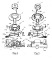
- the food processor or domestic appliance for cooking preparation illustrated in Figures 1 to 3 comprises a housing provided with a base 1 for receiving a container 2, bowl-shaped, provided with a handle 2a and closed by a 7.
- the base 1 is adjacent to a casing 3 in which is disposed a motor driving, by means of a transmission, a rotary tool 4 ( Figure 3) through the bottom of the container 2.
- the box 3 is provided in its upper part with a rotary knob 5 to control the start of the motor, the rotary knob 5 receiving in its center an unlocking button 6 of the cover 7.
- the apparatus comprises in its rear part (FIG. 2) a cable support 3a around which the motor power cable can be wound during his storage.
- the base 1 has a cavity serving as receiving housing at container 2, this impression comprising a lateral indentation 1a provided with a locking pin 1b under which the connecting arm of the handle 2a can be partially introduced and which constitutes a means of retaining the container 2 on the base 1.
- the lid 7 which is attached to the container 2 has a lower skirt inserting into the container to center the lid 7 and is edged a rib coming to rest on the upper edge of the container 2.
- the cover 7 has on its periphery a portion forming a portion of handle 7a completing the upper shape of the handle 2a of the container 2, the latter having a notched shape there.
- the handle portion 7a has, on one of its sides, a plate 7b to be placed adjacent to the handle 2a of the container when rotating the lid 7.
- This hook plate 7b has an opening forming a mortise in which is inserted a post 2b carried by the lateral edge of the handle 2a of the container, the penetration of the post 2b in the opening of the attachment plate 7b participating in the vertical retention of the lid 7 on the container 2.
- the hook plate 7b also serves as a lateral stop preventing rotation of the container 2 in the direction of disengagement of the connecting arm of the handle 2a from the spigot blocking 1b.
- the cover 7 comprises, facing the casing 3, a locking lug 8 which is inserted, by rotation of the cover 7, in a slot 9 of the box 3 when the handle portion 7a of the lid is brought into alignment with the handle 2a of the container.
- This locking tab 8 immobilizes the lid both vertically and in rotation.
- the locking of the lug 7 of the lid is carried out by means of a safety device placed inside the box 3.
- This safety device shown exploded in FIGS. 4 and 5, comprises a safety rod 10 which is sandwiched between a plate support 11 and a ring 12 driven in rotation by the button of motor control 5.
- the support plate 11 has a base plane arranged horizontally in the casing 3 and has cylindrical guide portions 110, inclined forward, at an angle of about 40 ° to the vertical, the upper ends of the guide portions 110 serving as a support plane to the crown 12.
- This bearing plane is perpendicular to the axial direction of the guide portions 110 and comprises a cavity, formed between the portions of cylindrical guide, serving as housing for the safety rod 10.
- the safety rod 10 has a body formed essentially of two walls lateral 101 interconnected by transverse partitions 102 and has, substantially midway between its two longitudinal ends, a transverse axis 103 constituting a pivot axis of the safety rod.
- the safety rod 10 also advantageously comprises a tongue elastic 109, visible in Figure 5, located in the extension of the axis transversal 103.
- the transverse axis 103 rests on the plate 11 in notches 111 made in the upper part of the two walls of the platen adjacent to the stem of safety, the transverse axis 103 having an inclination of the order of 40 ° by compared to the horizontal.
- the notches 111 extend horizontally over a length greater than diameter of the transverse axis 103 so that the rod 10 can translate longitudinally in the notches 111, the translation of the rod 10 on the plate 11 being radially to the cover 7 when the latter is positioned on the container 2.
- the safety rod 10 has an end, coming opposite the slot of the box 3, which is provided with a lower actuating ramp 104 and a ramp actuating upper 105 for cooperating with the tab 8 of the cover 7.
- This end also comprises a cavity 106 adapted to receive the end of the tab 8 of the cover 7.
- the safety rod 10 has at its opposite end, better visible on the FIG. 8, a tongue 107 inserted between the two branches of an element of guide 112 carried by the plate.
- This tongue 107 is surrounded by a spring recall 108 which is supported on the one hand on the body of the rod 10 and other part on an inclined plane 112a of the guide element 112.
- the ring 12 is attached to the plate 11, above the rod 10.
- This ring has a cylindrical portion 120 around three equidistant pins 113 protruding from the surface of the platinum 11, these three pins 113 being perpendicular to the support plane of the 12 and taking place at the edge of the inner surface of the part cylindrical 120 for guiding the rotation of the crown 12.
- the 12 is also provided with an elastic tongue 124 which comes into bearing against a wall 118 of the plate.
- the ring 12 has a rear skirt 121 in an arc extending towards the plate 11, parallel to the pins 113, and has two bosses 121a, better visible in Figure 10. These bosses 121 has come into contact with a fold 13a formed on a contact blade 13 of the switch controlling the power supply of the engine during the rotation of the crown 12, to move the contact blade 13 and close this switch.
- the control knob 5 of the engine which is attached to the crown 12, by the outside of the box 3, has a cylindrical central opening lined by three fingers 50 which take place around the cylindrical portion 120 of the crown 12 by inserting between ribs 122 so that the crown 12 is made integral in rotation of the control button 5.
- the unlocking button 6 of the cover 7 is attached to the center of the button 5 and comprises a tongue 60 extending axially to the central opening.
- This tongue 60 includes a ramp 60a coming to bear on an edge of the transverse axis 103 of the safety rod 10 of so that the depression of the unlocking button 6 causes a translation of the transverse axis 103 in the notches 111 in the direction of the removal of the safety rod 10 relative to the lid 7.
- the safety rod 10 can occupy a first, so-called unlocked position, in which the the safety rod 10 provided with the actuating ramps 105 and 106 is raised relative to the horizontal plane of the plate, the opposite end of the rod 10 is then finding in an inclined recess 114 of the plate 11 whose bottom acts as a pivot stop.
- This unlocked position corresponds to the position occupied by the safety rod 10 when the lug 8 of the lid 7 is disengaged from the slot of the box 3, for example when the lid 7 is not not present on the container 2.
- the rod of security 10 is offset longitudinally opposite the cover 7 of so that the transverse axis 103 is supported against the edge of the notch 111 opposite the lid 7.
- the spring 108 present on the rod of safety 10 is then in a substantially relaxed position and the rod of safety 10 has a lower transverse partition 102 which is in support against the lateral edge of the head of a hook 115 carried by the plate, the head of the hook 115 inserted between the side walls of the safety rod 10.
- the 115a side edge of the hook head 115 serves, in this position, stop longitudinal to the safety rod 10 so that the transverse axis 103 of the rod 10 is locked longitudinally in the notch 111.
- the safety rod 10 is driven to this position tilted by the couple of return generated by the relaxation force of the spring 108 on the inclined plane 112a, this effort being advantageously completed by the return force of the tongue elastic 109 carried by the safety rod 10 which then bears against a wall of the plate 11.
- the unlocking button 6 of the cover 7 then has the particularity to be slightly depressed inside the control knob 5 because of gravity movement of the unlocking button 6 until the ramp 60a bears against the transverse axis 103 which is then against the edge of the notch 111 opposite the cover 7.
- the spring 108 of the safety rod 10 When pivoting the safety rod 10 to this position, the spring 108 of the safety rod 10 is compressed gradually because of its contact with the inclined plane 112a, the safety rod 10 being at first blocked longitudinally by the support of its transverse partition 102 lower against the edge 115a of the hook head 115.
- the transverse partition 102 lower of the rod 10 can engage under the head of the hook 115, allowing movement longitudinally of the safety rod 10 towards the cover 7 under the force of the spring 108.
- the end of the locking lug 8 sinks into the cavity 106 complementary to the end of the safety rod so that the lid 7 is then immobilized on the container 2.
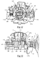
- FIG. 14 illustrates, by way of example, the rotation of the control button 5 counter-clockwise which allows to obtain the continuous operation of the motor of the apparatus, the ring 12 being immobilized in position works by the interaction of an elastic boss 123 with a finger 117 carried by platinum.
- Figure 15 illustrates the rotation of the control knob 5 clockwise which makes it possible to obtain operation of the motor of the apparatus by pulse, the rotation of the ring 12 then taking place by binding the tongue elastic 124 carried by the crown 12 whose end bears against the wall 118 of the plate so that the control button 5 is recalled elastically in its initial stop position when released.
- Such a safety device thus has the advantage of preventing any operation of the appliance motor when the lid is not correctly locked on the box and the handle of the container. Moreover, such safety device has the advantage of great compactness with a reduced number of parts and offers great ergonomics of use in allowing the concentric arrangement of the engine control knob and the lid release button.
- such a safety device makes it possible to dispense with a brake device on the tool by not allowing the lid to open immediately after stopping of the motor. After having returned the engine control knob in its stop position, the user is obliged to press the button of unlock and simultaneously turn the lid to get opening, which slows down the opening enough for the tool to stop naturally to turn.
Landscapes
- Engineering & Computer Science (AREA)
- Mechanical Engineering (AREA)
- Food Science & Technology (AREA)
- Food-Manufacturing Devices (AREA)
- General Preparation And Processing Of Foods (AREA)
- Closures For Containers (AREA)
- Cookers (AREA)
- Crushing And Pulverization Processes (AREA)
- Lock And Its Accessories (AREA)
Applications Claiming Priority (2)
| Application Number | Priority Date | Filing Date | Title |
|---|---|---|---|
| FR0401713 | 2004-02-20 | ||
| FR0401713A FR2866541B1 (fr) | 2004-02-20 | 2004-02-20 | Appareil electromenager de preparation culinaire |
Publications (3)
| Publication Number | Publication Date |
|---|---|
| EP1566129A2 true EP1566129A2 (de) | 2005-08-24 |
| EP1566129A3 EP1566129A3 (de) | 2005-08-31 |
| EP1566129B1 EP1566129B1 (de) | 2006-09-06 |
Family
ID=34708008
Family Applications (1)
| Application Number | Title | Priority Date | Filing Date |
|---|---|---|---|
| EP05356025A Expired - Lifetime EP1566129B1 (de) | 2004-02-20 | 2005-02-08 | Elektrisches Haushaltsgerät zur Nahrungszubereitung |
Country Status (6)
| Country | Link |
|---|---|
| EP (1) | EP1566129B1 (de) |
| AT (1) | ATE338499T1 (de) |
| DE (1) | DE602005000104D1 (de) |
| ES (1) | ES2271936T3 (de) |
| FR (1) | FR2866541B1 (de) |
| WO (1) | WO2005089608A1 (de) |
Cited By (5)
| Publication number | Priority date | Publication date | Assignee | Title |
|---|---|---|---|---|
| EP2433534A1 (de) | 2010-09-24 | 2012-03-28 | Seb S.A. | Haushaltsgerät mit einem Gefäss das ein von einem Motor angetriebenes Schneidewerkzeug umfasst |
| EP2433533A1 (de) | 2010-09-24 | 2012-03-28 | Seb S.A. | Haushaltsgerät mit einem Gefäss das ein von einem Motor angetriebenes Schneidewerkzeug umfasst |
| CN104939697A (zh) * | 2014-03-25 | 2015-09-30 | Seb公司 | 包括被与安全装置协作的可拆卸盖所关闭的容器的烹饪制备家电设备 |
| EP3185079A1 (de) * | 2015-12-21 | 2017-06-28 | ETA SA Manufacture Horlogère Suisse | Druckknopf-anordnung für eine elektronische oder elektromechanische armbanduhr |
| EP3766395A1 (de) * | 2019-07-19 | 2021-01-20 | BSH Hausgeräte GmbH | Behälter für ein küchengerät |
Families Citing this family (2)
| Publication number | Priority date | Publication date | Assignee | Title |
|---|---|---|---|---|
| CN107397459A (zh) * | 2016-05-18 | 2017-11-28 | 泓首翔电器(深圳)有限公司 | 一种食物处理器的盖合装置 |
| FR3157088B1 (fr) * | 2023-12-22 | 2025-11-21 | Hameur | Appareil de préparation d’aliments et tableau de commande pour un tel appareil |
Citations (1)
| Publication number | Priority date | Publication date | Assignee | Title |
|---|---|---|---|---|
| EP0025972A1 (de) | 1979-09-21 | 1981-04-01 | Moulinex S.A. | Elektrisches Haushaltsgerät zum Behandeln von Nahrungsmitteln |
Family Cites Families (2)
| Publication number | Priority date | Publication date | Assignee | Title |
|---|---|---|---|---|
| FR2422373A1 (fr) * | 1978-04-14 | 1979-11-09 | Moulinex Sa | Appareil electromenager de traitement des aliments |
| FR2447703A1 (fr) * | 1979-02-01 | 1980-08-29 | Seb Sa | Dispositif de securite pour appareil electro-domestique a organe rotatif |
-
2004
- 2004-02-20 FR FR0401713A patent/FR2866541B1/fr not_active Expired - Fee Related
-
2005
- 2005-02-08 WO PCT/FR2005/000274 patent/WO2005089608A1/fr not_active Ceased
- 2005-02-08 ES ES05356025T patent/ES2271936T3/es not_active Expired - Lifetime
- 2005-02-08 DE DE602005000104T patent/DE602005000104D1/de not_active Expired - Lifetime
- 2005-02-08 EP EP05356025A patent/EP1566129B1/de not_active Expired - Lifetime
- 2005-02-08 AT AT05356025T patent/ATE338499T1/de not_active IP Right Cessation
Patent Citations (1)
| Publication number | Priority date | Publication date | Assignee | Title |
|---|---|---|---|---|
| EP0025972A1 (de) | 1979-09-21 | 1981-04-01 | Moulinex S.A. | Elektrisches Haushaltsgerät zum Behandeln von Nahrungsmitteln |
Cited By (14)
| Publication number | Priority date | Publication date | Assignee | Title |
|---|---|---|---|---|
| CN102415831B (zh) * | 2010-09-24 | 2015-04-15 | Seb公司 | 包括容纳有由电动机驱动旋转的切割工具的容器的烹饪制备家电设备 |
| RU2565658C2 (ru) * | 2010-09-24 | 2015-10-20 | Себ С.А. | Электробытовое устройство для приготовления пищи, содержащее емкость, в которой находится режущий инструмент, приводимый во вращение двигателем |
| FR2965161A1 (fr) * | 2010-09-24 | 2012-03-30 | Seb Sa | Appareil electromenager de preparation culinaire comportant un recipient renfermant un outil coupant entraine en rotation par un moteur |
| FR2965162A1 (fr) * | 2010-09-24 | 2012-03-30 | Seb Sa | Appareil electromenager de preparation culinaire comportant un recipient renfermant un outil coupant entraine en rotation par un moteur |
| CN102415831A (zh) * | 2010-09-24 | 2012-04-18 | Seb公司 | 包括容纳有由电动机驱动旋转的切割工具的容器的烹饪制备家电设备 |
| CN102415830A (zh) * | 2010-09-24 | 2012-04-18 | Seb公司 | 包括容纳有由电动机驱动旋转的切割工具的容器的烹饪制备家电设备 |
| CN102415830B (zh) * | 2010-09-24 | 2015-05-06 | Seb公司 | 包括容纳有由电动机驱动旋转的切割工具的容器的烹饪制备家电设备 |
| EP2433534A1 (de) | 2010-09-24 | 2012-03-28 | Seb S.A. | Haushaltsgerät mit einem Gefäss das ein von einem Motor angetriebenes Schneidewerkzeug umfasst |
| EP2433533A1 (de) | 2010-09-24 | 2012-03-28 | Seb S.A. | Haushaltsgerät mit einem Gefäss das ein von einem Motor angetriebenes Schneidewerkzeug umfasst |
| CN104939697B (zh) * | 2014-03-25 | 2018-12-11 | Seb公司 | 包括被与安全装置协作的可拆卸盖所关闭的容器的烹饪制备家电设备 |
| CN104939697A (zh) * | 2014-03-25 | 2015-09-30 | Seb公司 | 包括被与安全装置协作的可拆卸盖所关闭的容器的烹饪制备家电设备 |
| EP3185079A1 (de) * | 2015-12-21 | 2017-06-28 | ETA SA Manufacture Horlogère Suisse | Druckknopf-anordnung für eine elektronische oder elektromechanische armbanduhr |
| US10068724B2 (en) | 2015-12-21 | 2018-09-04 | Eta Sa Manufacture Horlogere Suisse | Push-button arrangement for an electronic or electromechanical wristwatch |
| EP3766395A1 (de) * | 2019-07-19 | 2021-01-20 | BSH Hausgeräte GmbH | Behälter für ein küchengerät |
Also Published As
| Publication number | Publication date |
|---|---|
| EP1566129B1 (de) | 2006-09-06 |
| EP1566129A3 (de) | 2005-08-31 |
| ATE338499T1 (de) | 2006-09-15 |
| ES2271936T3 (es) | 2007-04-16 |
| WO2005089608A8 (fr) | 2005-11-24 |
| FR2866541B1 (fr) | 2006-04-14 |
| DE602005000104D1 (de) | 2006-10-19 |
| FR2866541A1 (fr) | 2005-08-26 |
| WO2005089608A1 (fr) | 2005-09-29 |
Similar Documents
| Publication | Publication Date | Title |
|---|---|---|
| EP1169955B1 (de) | Deckelverriegelungsvorrichtung | |
| EP2394547A1 (de) | Elektrohaushaltsgerät zur Essenszubereitung, das aus einem mit einem abnehmbaren Deckel verschlossenen Arbeitsbehälter besteht | |
| EP2335533B1 (de) | Haushaltsgerät zur Essenszubereitung, das zum Halten in der Hand konzipiert und mit einer speziellen Steuervorrichtung ausgestattet ist | |
| EP1130990B1 (de) | BEFESTIGUNGSMECHANISMUS ZUM FIXIEREN EINES DECKELS MIT EINGEBAUTEM MOTOR EINER KüCHENMASCHINE AUF EINER SCHüSSEL | |
| EP2651273A1 (de) | Elektrische küchenmaschine mit einem sockel für eine schüssel und einem fix mit dem sockel verbundenen arm | |
| EP2433533B1 (de) | Haushaltsgerät mit einem Gefäß, das ein von einem Motor angetriebenes Schneidewerkzeug umfasst | |
| FR2939298A1 (fr) | Appareil electromenager de preparation culinaire comportant un boitier supportant un bras de transmission amovible au dessus d'un recipient de travail | |
| WO2002051293A1 (fr) | Appareil electromenager de preparation culinaire comportant un dispositif de verrouillage d'un couvercle sur un recipient | |
| EP2433534B1 (de) | Haushaltsgerät mit einem Gefäß, das ein von einem Motor angetriebenes Schneidewerkzeug umfasst | |
| EP1566129B1 (de) | Elektrisches Haushaltsgerät zur Nahrungszubereitung | |
| EP1734851B1 (de) | Elektrischer wasserkessel | |
| FR2908620A1 (fr) | Appareil de preparation culinaire comportant des moyens particuliers d'immobilisation du recipient | |
| EP2651272A1 (de) | Elektrische küchenmaschine mit einem sockel für eine mit einem abnehmbarem deckel verschliessbare schüssel | |
| EP1520499B1 (de) | Elektrisches Haushaltsgerät zur Nahrungszubereitung | |
| EP2368469A1 (de) | Elektrohaushaltsgerät zur Essenzubereitung, das ein Motorgehäuse zur Aufnahme von verschiedenen Typen von auswechselbaren Zubehörteilen umfasst | |
| FR2954532A1 (fr) | Dispositif de commande d'un interrupteur d'appareil electromenager | |
| FR2769199A1 (fr) | Dispositif de securite pour appareil electromenager de preparation culinaire, du genre robot menager, et appareil comportant un tel dispositif | |
| EP1745728B1 (de) | Küchengerät mit rotierendem Werkzeug und spezieller Sicherheitsvorrichtung | |
| FR2717361A1 (fr) | Dispositif de sécurité pour un appareil de préparation des aliments. | |
| EP4104725B1 (de) | Elektrohaushaltsgerät zur essenszubereitung, das mit einem optimierten verriegelungssystem ausgestattet ist | |
| EP2433531B1 (de) | Vorrichtung zum Befestigen eines Gefässes oder eines Deckels eines Haushaltsgeräts | |
| FR2858001A1 (fr) | Serrure a pene dormant, manoeuvrable par bouton ou clef | |
| FR2769198A1 (fr) | Appareil electromenager de preparation culinaire, du genre robot menager, comportant un dispositif de deverrouillage simplifie | |
| FR2939297A1 (fr) | Appareil electromenager de preparation culinaire comportant un boitier supportant un bras de transmission amovible au dessus d'un recipient de travail |
Legal Events
| Date | Code | Title | Description |
|---|---|---|---|
| PUAI | Public reference made under article 153(3) epc to a published international application that has entered the european phase |
Free format text: ORIGINAL CODE: 0009012 |
|
| PUAL | Search report despatched |
Free format text: ORIGINAL CODE: 0009013 |
|
| 17P | Request for examination filed |
Effective date: 20050621 |
|
| AK | Designated contracting states |
Kind code of ref document: A2 Designated state(s): AT BE BG CH CY CZ DE DK EE ES FI FR GB GR HU IE IS IT LI LT LU MC NL PL PT RO SE SI SK TR |
|
| AX | Request for extension of the european patent |
Extension state: AL BA HR LV MK YU |
|
| AK | Designated contracting states |
Kind code of ref document: A3 Designated state(s): AT BE BG CH CY CZ DE DK EE ES FI FR GB GR HU IE IS IT LI LT LU MC NL PL PT RO SE SI SK TR |
|
| AX | Request for extension of the european patent |
Extension state: AL BA HR LV MK YU |
|
| GRAP | Despatch of communication of intention to grant a patent |
Free format text: ORIGINAL CODE: EPIDOSNIGR1 |
|
| AKX | Designation fees paid |
Designated state(s): AT BE BG CH CY CZ DE DK EE ES FI FR GB GR HU IE IS IT LI LT LU MC NL PL PT RO SE SI SK TR |
|
| GRAS | Grant fee paid |
Free format text: ORIGINAL CODE: EPIDOSNIGR3 |
|
| GRAA | (expected) grant |
Free format text: ORIGINAL CODE: 0009210 |
|
| AK | Designated contracting states |
Kind code of ref document: B1 Designated state(s): AT BE BG CH CY CZ DE DK EE ES FI FR GB GR HU IE IS IT LI LT LU MC NL PL PT RO SE SI SK TR |
|
| PG25 | Lapsed in a contracting state [announced via postgrant information from national office to epo] |
Ref country code: IT Free format text: LAPSE BECAUSE OF FAILURE TO SUBMIT A TRANSLATION OF THE DESCRIPTION OR TO PAY THE FEE WITHIN THE PRESCRIBED TIME-LIMIT;WARNING: LAPSES OF ITALIAN PATENTS WITH EFFECTIVE DATE BEFORE 2007 MAY HAVE OCCURRED AT ANY TIME BEFORE 2007. THE CORRECT EFFECTIVE DATE MAY BE DIFFERENT FROM THE ONE RECORDED. Effective date: 20060906 Ref country code: IE Free format text: LAPSE BECAUSE OF FAILURE TO SUBMIT A TRANSLATION OF THE DESCRIPTION OR TO PAY THE FEE WITHIN THE PRESCRIBED TIME-LIMIT Effective date: 20060906 Ref country code: PL Free format text: LAPSE BECAUSE OF FAILURE TO SUBMIT A TRANSLATION OF THE DESCRIPTION OR TO PAY THE FEE WITHIN THE PRESCRIBED TIME-LIMIT Effective date: 20060906 Ref country code: RO Free format text: LAPSE BECAUSE OF FAILURE TO SUBMIT A TRANSLATION OF THE DESCRIPTION OR TO PAY THE FEE WITHIN THE PRESCRIBED TIME-LIMIT Effective date: 20060906 Ref country code: FI Free format text: LAPSE BECAUSE OF FAILURE TO SUBMIT A TRANSLATION OF THE DESCRIPTION OR TO PAY THE FEE WITHIN THE PRESCRIBED TIME-LIMIT Effective date: 20060906 Ref country code: CZ Free format text: LAPSE BECAUSE OF FAILURE TO SUBMIT A TRANSLATION OF THE DESCRIPTION OR TO PAY THE FEE WITHIN THE PRESCRIBED TIME-LIMIT Effective date: 20060906 Ref country code: SI Free format text: LAPSE BECAUSE OF FAILURE TO SUBMIT A TRANSLATION OF THE DESCRIPTION OR TO PAY THE FEE WITHIN THE PRESCRIBED TIME-LIMIT Effective date: 20060906 Ref country code: SK Free format text: LAPSE BECAUSE OF FAILURE TO SUBMIT A TRANSLATION OF THE DESCRIPTION OR TO PAY THE FEE WITHIN THE PRESCRIBED TIME-LIMIT Effective date: 20060906 Ref country code: NL Free format text: LAPSE BECAUSE OF FAILURE TO SUBMIT A TRANSLATION OF THE DESCRIPTION OR TO PAY THE FEE WITHIN THE PRESCRIBED TIME-LIMIT Effective date: 20060906 Ref country code: LT Free format text: LAPSE BECAUSE OF FAILURE TO SUBMIT A TRANSLATION OF THE DESCRIPTION OR TO PAY THE FEE WITHIN THE PRESCRIBED TIME-LIMIT Effective date: 20060906 Ref country code: AT Free format text: LAPSE BECAUSE OF FAILURE TO SUBMIT A TRANSLATION OF THE DESCRIPTION OR TO PAY THE FEE WITHIN THE PRESCRIBED TIME-LIMIT Effective date: 20060906 |
|
| REG | Reference to a national code |
Ref country code: GB Ref legal event code: FG4D Free format text: NOT ENGLISH |
|
| REG | Reference to a national code |
Ref country code: CH Ref legal event code: EP |
|
| REG | Reference to a national code |
Ref country code: IE Ref legal event code: FG4D Free format text: LANGUAGE OF EP DOCUMENT: FRENCH |
|
| REF | Corresponds to: |
Ref document number: 602005000104 Country of ref document: DE Date of ref document: 20061019 Kind code of ref document: P |
|
| GBT | Gb: translation of ep patent filed (gb section 77(6)(a)/1977) |
Effective date: 20061103 |
|
| PG25 | Lapsed in a contracting state [announced via postgrant information from national office to epo] |
Ref country code: DK Free format text: LAPSE BECAUSE OF FAILURE TO SUBMIT A TRANSLATION OF THE DESCRIPTION OR TO PAY THE FEE WITHIN THE PRESCRIBED TIME-LIMIT Effective date: 20061206 Ref country code: BG Free format text: LAPSE BECAUSE OF FAILURE TO SUBMIT A TRANSLATION OF THE DESCRIPTION OR TO PAY THE FEE WITHIN THE PRESCRIBED TIME-LIMIT Effective date: 20061206 Ref country code: SE Free format text: LAPSE BECAUSE OF FAILURE TO SUBMIT A TRANSLATION OF THE DESCRIPTION OR TO PAY THE FEE WITHIN THE PRESCRIBED TIME-LIMIT Effective date: 20061206 |
|
| PG25 | Lapsed in a contracting state [announced via postgrant information from national office to epo] |
Ref country code: DE Free format text: LAPSE BECAUSE OF FAILURE TO SUBMIT A TRANSLATION OF THE DESCRIPTION OR TO PAY THE FEE WITHIN THE PRESCRIBED TIME-LIMIT Effective date: 20061207 |
|
| PG25 | Lapsed in a contracting state [announced via postgrant information from national office to epo] |
Ref country code: IS Free format text: LAPSE BECAUSE OF FAILURE TO SUBMIT A TRANSLATION OF THE DESCRIPTION OR TO PAY THE FEE WITHIN THE PRESCRIBED TIME-LIMIT Effective date: 20070106 |
|
| PG25 | Lapsed in a contracting state [announced via postgrant information from national office to epo] |
Ref country code: PT Free format text: LAPSE BECAUSE OF FAILURE TO SUBMIT A TRANSLATION OF THE DESCRIPTION OR TO PAY THE FEE WITHIN THE PRESCRIBED TIME-LIMIT Effective date: 20070219 |
|
| PG25 | Lapsed in a contracting state [announced via postgrant information from national office to epo] |
Ref country code: MC Free format text: LAPSE BECAUSE OF NON-PAYMENT OF DUE FEES Effective date: 20070228 |
|
| NLV1 | Nl: lapsed or annulled due to failure to fulfill the requirements of art. 29p and 29m of the patents act | ||
| REG | Reference to a national code |
Ref country code: ES Ref legal event code: FG2A Ref document number: 2271936 Country of ref document: ES Kind code of ref document: T3 |
|
| REG | Reference to a national code |
Ref country code: IE Ref legal event code: FD4D |
|
| PLBE | No opposition filed within time limit |
Free format text: ORIGINAL CODE: 0009261 |
|
| STAA | Information on the status of an ep patent application or granted ep patent |
Free format text: STATUS: NO OPPOSITION FILED WITHIN TIME LIMIT |
|
| 26N | No opposition filed |
Effective date: 20070607 |
|
| BERE | Be: lapsed |
Owner name: SEB S.A. Effective date: 20070228 |
|
| PG25 | Lapsed in a contracting state [announced via postgrant information from national office to epo] |
Ref country code: BE Free format text: LAPSE BECAUSE OF NON-PAYMENT OF DUE FEES Effective date: 20070228 |
|
| PG25 | Lapsed in a contracting state [announced via postgrant information from national office to epo] |
Ref country code: GR Free format text: LAPSE BECAUSE OF FAILURE TO SUBMIT A TRANSLATION OF THE DESCRIPTION OR TO PAY THE FEE WITHIN THE PRESCRIBED TIME-LIMIT Effective date: 20061207 |
|
| PG25 | Lapsed in a contracting state [announced via postgrant information from national office to epo] |
Ref country code: EE Free format text: LAPSE BECAUSE OF FAILURE TO SUBMIT A TRANSLATION OF THE DESCRIPTION OR TO PAY THE FEE WITHIN THE PRESCRIBED TIME-LIMIT Effective date: 20060906 |
|
| PGRI | Patent reinstated in contracting state [announced from national office to epo] |
Ref country code: IT Effective date: 20090501 |
|
| PG25 | Lapsed in a contracting state [announced via postgrant information from national office to epo] |
Ref country code: LU Free format text: LAPSE BECAUSE OF NON-PAYMENT OF DUE FEES Effective date: 20070208 Ref country code: CY Free format text: LAPSE BECAUSE OF FAILURE TO SUBMIT A TRANSLATION OF THE DESCRIPTION OR TO PAY THE FEE WITHIN THE PRESCRIBED TIME-LIMIT Effective date: 20060906 |
|
| PG25 | Lapsed in a contracting state [announced via postgrant information from national office to epo] |
Ref country code: HU Free format text: LAPSE BECAUSE OF FAILURE TO SUBMIT A TRANSLATION OF THE DESCRIPTION OR TO PAY THE FEE WITHIN THE PRESCRIBED TIME-LIMIT Effective date: 20070307 Ref country code: TR Free format text: LAPSE BECAUSE OF FAILURE TO SUBMIT A TRANSLATION OF THE DESCRIPTION OR TO PAY THE FEE WITHIN THE PRESCRIBED TIME-LIMIT Effective date: 20060906 |
|
| REG | Reference to a national code |
Ref country code: CH Ref legal event code: PL |
|
| PG25 | Lapsed in a contracting state [announced via postgrant information from national office to epo] |
Ref country code: LI Free format text: LAPSE BECAUSE OF NON-PAYMENT OF DUE FEES Effective date: 20090228 Ref country code: CH Free format text: LAPSE BECAUSE OF NON-PAYMENT OF DUE FEES Effective date: 20090228 |
|
| PGFP | Annual fee paid to national office [announced via postgrant information from national office to epo] |
Ref country code: ES Payment date: 20100223 Year of fee payment: 6 |
|
| PGFP | Annual fee paid to national office [announced via postgrant information from national office to epo] |
Ref country code: IT Payment date: 20100227 Year of fee payment: 6 |
|
| PGFP | Annual fee paid to national office [announced via postgrant information from national office to epo] |
Ref country code: GB Payment date: 20100127 Year of fee payment: 6 |
|
| GBPC | Gb: european patent ceased through non-payment of renewal fee |
Effective date: 20110208 |
|
| PG25 | Lapsed in a contracting state [announced via postgrant information from national office to epo] |
Ref country code: IT Free format text: LAPSE BECAUSE OF NON-PAYMENT OF DUE FEES Effective date: 20110208 |
|
| PG25 | Lapsed in a contracting state [announced via postgrant information from national office to epo] |
Ref country code: GB Free format text: LAPSE BECAUSE OF NON-PAYMENT OF DUE FEES Effective date: 20110208 |
|
| REG | Reference to a national code |
Ref country code: ES Ref legal event code: FD2A Effective date: 20120411 |
|
| PG25 | Lapsed in a contracting state [announced via postgrant information from national office to epo] |
Ref country code: ES Free format text: LAPSE BECAUSE OF NON-PAYMENT OF DUE FEES Effective date: 20110209 |
|
| PGFP | Annual fee paid to national office [announced via postgrant information from national office to epo] |
Ref country code: FR Payment date: 20140228 Year of fee payment: 10 |
|
| REG | Reference to a national code |
Ref country code: FR Ref legal event code: ST Effective date: 20151030 |
|
| PG25 | Lapsed in a contracting state [announced via postgrant information from national office to epo] |
Ref country code: FR Free format text: LAPSE BECAUSE OF NON-PAYMENT OF DUE FEES Effective date: 20150302 |