EP1565965B1 - Tafelmontierbarer elektrischer verbinder - Google Patents
Tafelmontierbarer elektrischer verbinder Download PDFInfo
- Publication number
- EP1565965B1 EP1565965B1 EP03787102A EP03787102A EP1565965B1 EP 1565965 B1 EP1565965 B1 EP 1565965B1 EP 03787102 A EP03787102 A EP 03787102A EP 03787102 A EP03787102 A EP 03787102A EP 1565965 B1 EP1565965 B1 EP 1565965B1
- Authority
- EP
- European Patent Office
- Prior art keywords
- panel
- projection
- connector
- retention cap
- housing
- Prior art date
- Legal status (The legal status is an assumption and is not a legal conclusion. Google has not performed a legal analysis and makes no representation as to the accuracy of the status listed.)
- Expired - Lifetime
Links
- 230000014759 maintenance of location Effects 0.000 claims abstract description 38
- 230000013011 mating Effects 0.000 claims abstract description 26
- 230000002093 peripheral effect Effects 0.000 claims description 7
- 230000000295 complement effect Effects 0.000 description 1
- 238000004519 manufacturing process Methods 0.000 description 1
- 238000007789 sealing Methods 0.000 description 1
Images

Classifications
-
- H—ELECTRICITY
- H01—ELECTRIC ELEMENTS
- H01R—ELECTRICALLY-CONDUCTIVE CONNECTIONS; STRUCTURAL ASSOCIATIONS OF A PLURALITY OF MUTUALLY-INSULATED ELECTRICAL CONNECTING ELEMENTS; COUPLING DEVICES; CURRENT COLLECTORS
- H01R13/00—Details of coupling devices of the kinds covered by groups H01R12/70 or H01R24/00 - H01R33/00
- H01R13/62—Means for facilitating engagement or disengagement of coupling parts or for holding them in engagement
- H01R13/629—Additional means for facilitating engagement or disengagement of coupling parts, e.g. aligning or guiding means, levers, gas pressure electrical locking indicators, manufacturing tolerances
- H01R13/631—Additional means for facilitating engagement or disengagement of coupling parts, e.g. aligning or guiding means, levers, gas pressure electrical locking indicators, manufacturing tolerances for engagement only
- H01R13/6315—Additional means for facilitating engagement or disengagement of coupling parts, e.g. aligning or guiding means, levers, gas pressure electrical locking indicators, manufacturing tolerances for engagement only allowing relative movement between coupling parts, e.g. floating connection
-
- H—ELECTRICITY
- H01—ELECTRIC ELEMENTS
- H01R—ELECTRICALLY-CONDUCTIVE CONNECTIONS; STRUCTURAL ASSOCIATIONS OF A PLURALITY OF MUTUALLY-INSULATED ELECTRICAL CONNECTING ELEMENTS; COUPLING DEVICES; CURRENT COLLECTORS
- H01R13/00—Details of coupling devices of the kinds covered by groups H01R12/70 or H01R24/00 - H01R33/00
- H01R13/73—Means for mounting coupling parts to apparatus or structures, e.g. to a wall
- H01R13/74—Means for mounting coupling parts in openings of a panel
- H01R13/741—Means for mounting coupling parts in openings of a panel using snap fastening means
- H01R13/745—Means for mounting coupling parts in openings of a panel using snap fastening means separate from the housing
-
- H—ELECTRICITY
- H01—ELECTRIC ELEMENTS
- H01R—ELECTRICALLY-CONDUCTIVE CONNECTIONS; STRUCTURAL ASSOCIATIONS OF A PLURALITY OF MUTUALLY-INSULATED ELECTRICAL CONNECTING ELEMENTS; COUPLING DEVICES; CURRENT COLLECTORS
- H01R24/00—Two-part coupling devices, or either of their cooperating parts, characterised by their overall structure
- H01R24/38—Two-part coupling devices, or either of their cooperating parts, characterised by their overall structure having concentrically or coaxially arranged contacts
- H01R24/40—Two-part coupling devices, or either of their cooperating parts, characterised by their overall structure having concentrically or coaxially arranged contacts specially adapted for high frequency
- H01R24/52—Two-part coupling devices, or either of their cooperating parts, characterised by their overall structure having concentrically or coaxially arranged contacts specially adapted for high frequency mounted in or to a panel or structure
Definitions
- This invention generally relates to the art of electrical connectors and, particularly, to an electrical connector for mounting through an aperture in a panel and provided with floating movement between the connector and the panel.
- a connector housing may be disposed at a first or rear side of the panel, with a mating portion of the connector projecting through the aperture to a position projecting from a second or front side of the panel.
- the connector float" relative to the panel. In other words, the connector can move within the aperture relative to the panel.
- the present invention is directed to solving these problems by providing a very simple connector according to claim 1, simply by inserting the connector through the aperture in the panel.
- An object, therefore, of the invention is to provide a new and improved panel mounted electrical connector of the character described.
- Another object of the invention is to provide a new and improved electrical connector for mounting through an aperture in a panel, with floating movement between the connector and the panel.
- a connector housing includes a mating portion insertable from a first side of the panel, through the aperture, to a position projecting from a second side of the panel.
- a first projection is provided on the housing for engaging the first side of the panel.
- a spring retention cap is positioned about the mating portion on the second side of the panel and includes a second projection for engaging the second side of the panel.
- An extension spring has opposite ends fixed to the spring retention cap and to the housing for drawing the first projection on the housing and the second projection on the spring retention cap against the first and second sides of the panel. The extension spring provides for floating movement between the connector and the panel.
- the extension spring is a coil spring stretched in tension between the housing and the spring retention cap.
- the cap is cup-shaped to define an inner bottom wall and side walls forming an interior cavity within which the coil spring is disposed.
- One end of the spring is fixed to the inner bottom wall of the cup-shaped spring retention cap.
- the mating portion of the connector housing extends through an opening in the bottom wall of the cup-shaped spring retention cap.
- the spring retention cap is dimensioned for passing through the aperture in the panel when the mating portion of the connector housing is inserted from the first side of the panel through the aperture.
- the second projection on the spring retention cap passes through the panel into snapped engagement with the second side of the panel.
- the second projection is located on a compressible portion of the spring retention cap, whereby the second projection snappingly expands into engagement with the second side of the panel when the second projection clears the aperture in the panel.
- the first projection on the housing is provided by a peripheral flange which may be press-fit onto the mating portion of the connector housing.
- the flange may be integral with and surround the mating portion of the connector housing.
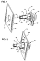
- Figure 1 the invention is embodied in an electrical connector, generally designated 10, for mounting through an aperture 12 in a panel 14 in the direction of arrow "A".
- Figure 2 shows the connector fully mounted within the aperture in the panel, and floating movement is provided between the connector and the panel.
- electrical connector 10 includes a connector housing, generally designated 16, which has a mating portion 18 which is insertable in the direction of arrow "A" (Fig. 1) from a first or rear side 14a of panel 14, through aperture 12, to a position projecting from a second or front side 14b of the panel as seen in Figures 2 and 3.
- Housing 16 has a first projection in the form of a peripheral flange 20 for engaging rear side 14a of the panel as seen in Figure 3.
- a spring retention cap is positioned about mating portion 18 and, when the connector is mounted through the aperture in the panel, the spring retention cap is located at the front side 14b of the panel and includes a second projection in the form of a peripheral flange 24 for engaging the front side of the panel.
- an extension spring 26 has opposite ends 26a and 26b, respectively, fixed to spring retention cap 22 and to flange 20 of housing 16.
- extension spring 26 is a coil spring stretched in tension between the spring retention cap and the housing. Opposite ends 26a and 26b of the coil spring are hooked into holes 28a and 28b, respectively, in the spring retention cap and flange 20 to maintain the spring in its extended or stretched condition. Therefore, the spring is effective for drawing the first projection (flange) 20 on housing 16 and the second projection (flange) 24 on spring retention cap 22 against the first and second sides 14a and 14b, respectively, of panel 14.
- spring retention cap 22 is generally cup-shaped to define an inner bottom wall 30 and a cylindrical side wall 32 which forms an interior cavity 34 within which coil spring 26 is disposed. End 26a of the coil spring is fixed to inner bottom wall 30 of the cup-shaped spring retention cap.
- the bottom wall includes an opening 36 through which mating portion 18 of connector 10 extends.
- Spring retention cap 22 is dimensioned for passing through aperture 12 in panel 14 when mating portion 18 of the connector is inserted from rear side 14a of the panel through the aperture.
- the inner end of the spring retention cap is compressible by providing a plurality of slits 38 which effectively define a plurality of flexible fingers 40 circumferentially about the retention cap.
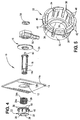
- the second projection 24 (Fig. 3) for engaging front side 14b of panel 14 actually is defined by a plurality of flange sections 42 as seen in Figure 5, with the flange sections projecting outwardly from flexible fingers 40. Therefore, when the connector is inserted through aperture 12 in panel 14 in the direction of arrow "A" (Fig.
- flexible fingers 40 flex inwardly to compress the inner end of the spring retention cap and allow flange sections 42 to pass through the aperture. When the flange sections clear the aperture, flexible fingers 40 "snap" back outwardly so that flange sections 42 form the second projection 24 (Fig. 3) for engaging front side 14b of the panel.
- electrical connector 10 can take a wide variety of configurations.
- connector 10 herein is structured as an antenna connector for use with mobile cell phones or the like.
- the connector includes a central terminal 50 (Fig. 3) which is coupled to a coaxial cable (not shown) which extends into the connector through a rear boot 52.
- the boot is secured to connector housing 16 which, itself, can take a variety of configurations.
- mating portion 18 is shown as a separate component (see Fig. 4) of housing 16, but the mating portion could be an integral portion of the housing.
- Terminal 50 is surrounded by a dielectric 54 which is disposed within the mating portion.
- a sealing cap 56 closes the rear of housing 16, and a front distal end 18a of mating portion 18 is compressible for mating with a complementary connector (not shown). Repeating, all of these various components of connector 10 and connector housing 16 can be varied considerably within the concepts of the invention.
- first projection provided by peripheral flange 20 on connector housing 16 for engaging rear side 14a of panel 14 also can vary from the configuration shown in the drawings.
- flange 20 may be press-fit about mating portion 18 of the connector housing.
- the peripheral flange may be integral with the mating portion or other portions of the connector housing.
- connector 10 When connector 10 is mounted within aperture 12 in panel 14 as seen in Figures 2 and 3, spring retention cap 22 and connector housing 16 can move relative to each other because the connection therebetween is provided solely by extension spring 26. Therefore, the connector can "float” or move relative to panel 14 both axially as well as radially within aperture 12. In addition, the entire connector can rotate or twist about an axis through the center of the aperture relative to the panel.
Landscapes
- Connector Housings Or Holding Contact Members (AREA)
- Details Of Connecting Devices For Male And Female Coupling (AREA)
- Coupling Device And Connection With Printed Circuit (AREA)
Claims (8)
- Elektrischer Verbinder (10) zur Montage durch eine Öffnung (12) in einer Platte (14) hindurch, und zwar mit schwimmender Beweglichkeit zwischen dem Verbinder und der Platte, umfassend:ein Verbindergehäuse (16) mit einem Paarungsabschnitt (18), der von einer ersten Seite (14a) der Platte aus durch die Öffnung (12) hindurch in eine Stellung eingefügt werden kann, bei welcher er von einer zweiten Seite (14b) der Platte vorsteht, und mit einem ersten Vorsprung (20) an dem Gehäuse zur Anlage an der ersten Seite (14a) der Platte;eine einstückige Federrückhaltekappe (22), die an der zweiten Seite (14b) der Platte um den Paarungsabschnitt (18) herum angeordnet ist und einen zweiten Vorsprung (24) zur Anlage an der zweiten Seite (14b) der Platte aufweist, wobei die Federrückhaltekappe zum Durchführen durch die in der Platte vorgesehene Öffnung (12) bemessen ist, wenn der Paarungsabschnitt (18) des Verbindergehäuses von der ersten Seite der Platte aus durch die Öffnung hindurch eingefügt wird, wobei der an der Federrückhaltekappe vorgesehene zweite Vorsprung (24) durch die in der Platte vorgesehene Öffnung (12) bis zur Anlage an der zweiten Seite (14b) der Platte hindurchschnappt, wobei die Federrückhaltekappe eine Bodenwandung (30) mit einer Öffnung (36) aufweist, durch welche hindurch sich der Paarungsabschnitt (18) des Verbinders (10) verschiebbar erstreckt; undeine Zugfeder (26) mit entgegengesetzten Enden (26a, 26b), die an der Federrückhaltekappe und an dem Gehäuse befestigt sind, um den an dem Gehäuse vorgesehenen ersten Vorsprung (20) und den an der Federrückhaltekappe vorgesehenen zweiten Vorsprung (24) gegen die erste und die zweite Seite (14a, 14b) der Platte zu ziehen.
- Elektrischer Verbinder nach Anspruch 1,
wobei die Zugfeder (26) eine Schraubenfeder umfasst, die in Zugspannung zwischen dem Gehäuse (16) und der Federrückhaltekappe (22) gedehnt ist. - Elektrischer Verbinder nach Anspruch 1 oder 2,
wobei die Federrückhaltekappe (22) schalenförmig vorgesehen ist, so dass eine innere Bodenwand (30) und Seitenwände (32) definiert sind, welche einen inneren Hohlraum (34) bilden, in welchem die Zugfeder (26) angeordnet ist. - Elektrischer Verbinder nach Anspruch 3,
wobei ein Ende (26a) der Zugfeder (26) an der inneren Bodenwand (30) der schalenförmigen Federrückhaltekappe befestigt ist. - Elektrischer Verbinder nach Anspruch 1,
wobei der zweite Vorsprung (24) an einem zusammendrückbaren Abschnitt (40) der Federrückhaltekappe (22) angeordnet ist, wodurch sich der zweite Vorsprung bis zur Anlage an der zweiten Seite (14b) der Platte ausdehnt, wenn der zweite Vorsprung von der in der Platte vorgesehenen Öffnung (12) freigegeben wird. - Elektrischer Verbinder nach Anspruch 1,
wobei der erste Vorsprung (20) einen umfänglichen Flansch umfasst, der in Presspassung an dem Paarungsabschnitt (18) des Verbindergehäuses angebracht ist. - Elektrischer Verbinder nach Anspruch 1,
wobei der erste Vorsprung (20) einen integral mit dem Paarungsabschnitt (18) des Verbindergehäuses vorgesehenen und diesen umschließenden umfänglichen Flansch umfasst. - Elektrischer Verbinder nach Anspruch 1,
wobei der zusammendrückbare Abschnitt (40) der Federrückhaltekappe Schlitze aufweist, so dass flexible Finger bestimmt sind, wobei der zweite Vorsprung (24) durch Flanschmittel (42) an zumindest einigen der flexiblen Finger bereitgestellt ist.
Applications Claiming Priority (3)
| Application Number | Priority Date | Filing Date | Title |
|---|---|---|---|
| US304733 | 1994-09-12 | ||
| US10/304,733 US6679726B1 (en) | 2002-11-26 | 2002-11-26 | Panel mounted electrical connector |
| PCT/US2003/037569 WO2004049519A1 (en) | 2002-11-26 | 2003-11-24 | Panel mounted electrical connector |
Publications (2)
| Publication Number | Publication Date |
|---|---|
| EP1565965A1 EP1565965A1 (de) | 2005-08-24 |
| EP1565965B1 true EP1565965B1 (de) | 2006-04-19 |
Family
ID=30000290
Family Applications (1)
| Application Number | Title | Priority Date | Filing Date |
|---|---|---|---|
| EP03787102A Expired - Lifetime EP1565965B1 (de) | 2002-11-26 | 2003-11-24 | Tafelmontierbarer elektrischer verbinder |
Country Status (7)
| Country | Link |
|---|---|
| US (1) | US6679726B1 (de) |
| EP (1) | EP1565965B1 (de) |
| JP (1) | JP4048503B2 (de) |
| CN (1) | CN100429842C (de) |
| AU (1) | AU2003295888A1 (de) |
| DE (1) | DE60304732T2 (de) |
| WO (1) | WO2004049519A1 (de) |
Families Citing this family (30)
| Publication number | Priority date | Publication date | Assignee | Title |
|---|---|---|---|---|
| US6905360B2 (en) * | 2002-06-26 | 2005-06-14 | Emerson Electric Co. | Power cord connector for an appliance |
| KR101176817B1 (ko) * | 2003-04-07 | 2012-08-24 | 가부시키가이샤 니콘 | 노광장치 및 디바이스 제조방법 |
| ITTO20030485A1 (it) * | 2003-06-26 | 2004-12-27 | Olsa Spa | Dispositivo di assemblaggio per gruppi ottici ad una carrozzeria |
| US7175481B1 (en) | 2005-11-01 | 2007-02-13 | Walbro Engine Management, L.L.C. | Sealed pass-through electrical connector |
| US7077697B2 (en) * | 2004-09-09 | 2006-07-18 | Corning Gilbert Inc. | Snap-in float-mount electrical connector |
| DE102005013282A1 (de) * | 2005-03-22 | 2006-09-28 | Rosenberger Hochfrequenztechnik Gmbh & Co. Kg | Steckverbinder |
| CN2862418Y (zh) * | 2005-12-06 | 2007-01-24 | 富士康(昆山)电脑接插件有限公司 | 线缆连接器组件 |
| USD593248S1 (en) * | 2005-12-14 | 2009-05-26 | Quintin Robert G | Hanging engine lamp |
| DE102006015718A1 (de) * | 2006-04-04 | 2007-10-11 | Escha Bauelemente Gmbh | Verteilersystem und Verfahren zu seiner Herstellung |
| US7326063B1 (en) * | 2007-02-06 | 2008-02-05 | Tyco Electronics Corporation | Panel mount connector housing |
| US8622762B2 (en) | 2010-11-22 | 2014-01-07 | Andrew Llc | Blind mate capacitively coupled connector |
| US8550859B2 (en) | 2011-10-20 | 2013-10-08 | Andrew Llc | Close proximity panel mount connectors |
| DE102010054801A1 (de) * | 2010-12-16 | 2012-06-21 | Andrew Wireless Systems Gmbh | HF-Verbindungselement und HF-Gerät |
| USD711583S1 (en) * | 2011-09-28 | 2014-08-19 | Wavesquare Inc. | Lighting element |
| CN103959555B (zh) | 2011-12-22 | 2017-03-08 | 康普技术有限责任公司 | 电容性盲插模块互连 |
| USD700992S1 (en) * | 2012-08-28 | 2014-03-11 | Ingenuity Inventions, LLC | Flashing light assembly |
| US8801460B2 (en) | 2012-11-09 | 2014-08-12 | Andrew Llc | RF shielded capacitively coupled connector |
| US8747152B2 (en) | 2012-11-09 | 2014-06-10 | Andrew Llc | RF isolated capacitively coupled connector |
| US9553440B2 (en) | 2013-11-18 | 2017-01-24 | Walbro Llc | Wire seal assembly |
| CN104682058B (zh) * | 2015-02-12 | 2017-08-08 | 镇江日鑫电子有限公司(中外合资) | 用以插孔连接器组合的组装模具及组装方法 |
| US9337577B1 (en) * | 2015-03-31 | 2016-05-10 | Tyco Electronics Corporation | Floatable connector |
| EP3174167B1 (de) * | 2015-11-30 | 2021-02-17 | Teleste Oyj | Koaxialkabelerweiterung |
| WO2017173309A1 (en) * | 2016-03-31 | 2017-10-05 | Molex, Llc | Panel mount connector |
| US10090659B2 (en) | 2017-02-16 | 2018-10-02 | Bridgeport Fittings, Inc. | Raintight fitting for jacketed metal clad cables |
| US10290968B2 (en) * | 2017-05-02 | 2019-05-14 | Neptune Technology Group | Waterproof coaxial cable connector |
| US10535934B1 (en) * | 2018-04-26 | 2020-01-14 | Juniper Networks, Inc. | Apparatus, system, and method for achieving PCB-compatible power sockets |
| US11152746B2 (en) * | 2018-08-01 | 2021-10-19 | Eaton Intelligent Power Limited | Electrical connector |
| US10992087B2 (en) * | 2018-12-13 | 2021-04-27 | Amphenol Corporation | Contact member for electrical connector |
| US11804670B1 (en) | 2021-09-17 | 2023-10-31 | The United States Of America As Represented By The Secretary Of The Navy | Electrical signal connector receptacle assembly for use with access port |
| CN116131027B (zh) * | 2023-03-07 | 2025-12-16 | 上海传输线研究所(中国电子科技集团公司第二十三研究所) | 一种浮动式连接器组件 |
Family Cites Families (24)
| Publication number | Priority date | Publication date | Assignee | Title |
|---|---|---|---|---|
| US3091748A (en) | 1959-11-09 | 1963-05-28 | Gen Dynamics Corp | Electrical connector |
| NL266688A (de) | 1960-07-08 | |||
| US3235834A (en) * | 1964-01-10 | 1966-02-15 | Amp Inc | Shielded braid pin and socket connector |
| US3366920A (en) * | 1965-11-22 | 1968-01-30 | Amp Inc | Coaxial connector |
| GB1289312A (de) * | 1968-11-26 | 1972-09-13 | ||
| US4070559A (en) | 1975-12-08 | 1978-01-24 | Cutler-Hammer, Inc. | Snap-in means for mounting electrical devices or the like in a support panel aperture |
| US4173384A (en) * | 1978-08-23 | 1979-11-06 | The United States Of America As Represented By The Secretary Of The Navy | Flexible co-axial connector for cable in-line electronics |
| US4227765A (en) | 1979-02-12 | 1980-10-14 | Raytheon Company | Coaxial electrical connector |
| US4451103A (en) * | 1981-12-14 | 1984-05-29 | Rockwell International Corporation | Connector assembly |
| DE3334550A1 (de) | 1982-09-29 | 1984-03-29 | Automatic Connector, Inc., Commack, N.Y. | Elektrischer steckverbinder |
| US4580862A (en) * | 1984-03-26 | 1986-04-08 | Amp Incorporated | Floating coaxial connector |
| US4734046A (en) * | 1984-09-21 | 1988-03-29 | International Business Machines Corporation | Coaxial converter with resilient terminal |
| US4697859A (en) | 1986-08-15 | 1987-10-06 | Amp Incorporated | Floating coaxial connector |
| US4867698A (en) | 1988-02-03 | 1989-09-19 | Amp Incorporated | Antenna Connector |
| US5167520A (en) | 1991-10-18 | 1992-12-01 | Amp Incorporated | Cup fit plug connector |
| US5383798A (en) * | 1993-08-16 | 1995-01-24 | Lin; Lark | VCR terminal connector |
| US5516303A (en) | 1995-01-11 | 1996-05-14 | The Whitaker Corporation | Floating panel-mounted coaxial connector for use with stripline circuit boards |
| JP3286183B2 (ja) | 1996-09-30 | 2002-05-27 | アジレント・テクノロジー株式会社 | 同軸コネクタフローティングマウント装置 |
| US5769652A (en) | 1996-12-31 | 1998-06-23 | Applied Engineering Products, Inc. | Float mount coaxial connector |
| US6224407B1 (en) | 1997-12-17 | 2001-05-01 | The Whitaker Corporation | Coaxial switch connector assembly |
| EP0967693B1 (de) * | 1998-06-22 | 2003-12-03 | The Whitaker Corporation | Schwimmende Steckeranordnung |
| US6344736B1 (en) * | 1999-07-22 | 2002-02-05 | Tensolite Company | Self-aligning interface apparatus for use in testing electrical |
| TW488116B (en) * | 2000-03-31 | 2002-05-21 | Matsushita Electric Works Ltd | Receptacle for coaxial plug connector |
| US6592268B2 (en) * | 2000-05-09 | 2003-07-15 | Molex Incorporated | Connector assembly floating mount |
-
2002
- 2002-11-26 US US10/304,733 patent/US6679726B1/en not_active Expired - Fee Related
-
2003
- 2003-11-24 WO PCT/US2003/037569 patent/WO2004049519A1/en not_active Ceased
- 2003-11-24 JP JP2004555691A patent/JP4048503B2/ja not_active Expired - Fee Related
- 2003-11-24 AU AU2003295888A patent/AU2003295888A1/en not_active Abandoned
- 2003-11-24 EP EP03787102A patent/EP1565965B1/de not_active Expired - Lifetime
- 2003-11-24 DE DE60304732T patent/DE60304732T2/de not_active Expired - Fee Related
- 2003-11-24 CN CNB2003801075128A patent/CN100429842C/zh not_active Expired - Fee Related
Also Published As
| Publication number | Publication date |
|---|---|
| AU2003295888A1 (en) | 2004-06-18 |
| DE60304732T2 (de) | 2007-04-12 |
| CN100429842C (zh) | 2008-10-29 |
| CN1732600A (zh) | 2006-02-08 |
| EP1565965A1 (de) | 2005-08-24 |
| WO2004049519A1 (en) | 2004-06-10 |
| DE60304732D1 (de) | 2006-05-24 |
| US6679726B1 (en) | 2004-01-20 |
| JP4048503B2 (ja) | 2008-02-20 |
| JP2006508507A (ja) | 2006-03-09 |
Similar Documents
| Publication | Publication Date | Title |
|---|---|---|
| US6679726B1 (en) | Panel mounted electrical connector | |
| US5951336A (en) | Terminal fitting | |
| US5766041A (en) | Shield member for panel mount connector | |
| EP0362598B1 (de) | Elektrischer Verbinder | |
| US4743205A (en) | Female coaxial connector and method of making the same | |
| US5158391A (en) | Sealing structure of waterproof connector | |
| US5613877A (en) | Electric connector boardlock | |
| EP0821437A1 (de) | Kontaktbüchsearmatur | |
| EP1162698B1 (de) | Kontaktbüchsenarmatur | |
| JP6116751B2 (ja) | 可変角度emi遮蔽アセンブリ | |
| JP3319292B2 (ja) | 雌側端子金具 | |
| US7918695B2 (en) | Tubular female terminal for receiving a male terminal | |
| CA2199069C (en) | Connector module, connector module kit and connector module and panel assembly | |
| EP0740368B1 (de) | Rohrförmige Haltevorrichtung | |
| US5092794A (en) | Shielded electrical connector | |
| US20030082951A1 (en) | Electric connector | |
| US20200313329A1 (en) | Method of forming an electrical terminal and an electrical terminal assembly | |
| US20060211293A1 (en) | Connector assembly with strain relief member | |
| KR102517170B1 (ko) | 고전압 커넥터용 쉴드쉘 | |
| US20020177371A1 (en) | Connector | |
| US5711687A (en) | Electrical terminal with locking lance | |
| US7097505B1 (en) | Shielded electrical connector | |
| KR102095155B1 (ko) | 고전압 쉴드 커넥터 | |
| JP3067473B2 (ja) | パネル取付型コネクタ | |
| US6398597B1 (en) | Receptacle contact of a cable assembly and the cable assembly using the same |
Legal Events
| Date | Code | Title | Description |
|---|---|---|---|
| PUAI | Public reference made under article 153(3) epc to a published international application that has entered the european phase |
Free format text: ORIGINAL CODE: 0009012 |
|
| 17P | Request for examination filed |
Effective date: 20050609 |
|
| AK | Designated contracting states |
Kind code of ref document: A1 Designated state(s): AT BE BG CH CY CZ DE DK EE ES FI FR GB GR HU IE IT LI LU MC NL PT RO SE SI SK TR |
|
| AX | Request for extension of the european patent |
Extension state: AL LT LV MK |
|
| GRAP | Despatch of communication of intention to grant a patent |
Free format text: ORIGINAL CODE: EPIDOSNIGR1 |
|
| GRAS | Grant fee paid |
Free format text: ORIGINAL CODE: EPIDOSNIGR3 |
|
| GRAA | (expected) grant |
Free format text: ORIGINAL CODE: 0009210 |
|
| DAX | Request for extension of the european patent (deleted) | ||
| RBV | Designated contracting states (corrected) |
Designated state(s): DE |
|
| AK | Designated contracting states |
Kind code of ref document: B1 Designated state(s): DE |
|
| REF | Corresponds to: |
Ref document number: 60304732 Country of ref document: DE Date of ref document: 20060524 Kind code of ref document: P |
|
| PLBE | No opposition filed within time limit |
Free format text: ORIGINAL CODE: 0009261 |
|
| STAA | Information on the status of an ep patent application or granted ep patent |
Free format text: STATUS: NO OPPOSITION FILED WITHIN TIME LIMIT |
|
| 26N | No opposition filed |
Effective date: 20070122 |
|
| PGFP | Annual fee paid to national office [announced via postgrant information from national office to epo] |
Ref country code: DE Payment date: 20081223 Year of fee payment: 6 |
|
| PG25 | Lapsed in a contracting state [announced via postgrant information from national office to epo] |
Ref country code: DE Free format text: LAPSE BECAUSE OF NON-PAYMENT OF DUE FEES Effective date: 20100601 |