EP1565755B2 - Detecteur de position - Google Patents
Detecteur de position Download PDFInfo
- Publication number
- EP1565755B2 EP1565755B2 EP03795827.9A EP03795827A EP1565755B2 EP 1565755 B2 EP1565755 B2 EP 1565755B2 EP 03795827 A EP03795827 A EP 03795827A EP 1565755 B2 EP1565755 B2 EP 1565755B2
- Authority
- EP
- European Patent Office
- Prior art keywords
- position detector
- ferromagnetic element
- detector according
- magnet
- ferromagnetic
- Prior art date
- Legal status (The legal status is an assumption and is not a legal conclusion. Google has not performed a legal analysis and makes no representation as to the accuracy of the status listed.)
- Expired - Lifetime
Links
Images


Classifications
-
- G—PHYSICS
- G01—MEASURING; TESTING
- G01P—MEASURING LINEAR OR ANGULAR SPEED, ACCELERATION, DECELERATION, OR SHOCK; INDICATING PRESENCE, ABSENCE, OR DIRECTION, OF MOVEMENT
- G01P13/00—Indicating or recording presence, absence, or direction, of movement
- G01P13/02—Indicating direction only, e.g. by weather vane
- G01P13/04—Indicating positive or negative direction of a linear movement or clockwise or anti-clockwise direction of a rotational movement
-
- G—PHYSICS
- G01—MEASURING; TESTING
- G01D—MEASURING NOT SPECIALLY ADAPTED FOR A SPECIFIC VARIABLE; ARRANGEMENTS FOR MEASURING TWO OR MORE VARIABLES NOT COVERED IN A SINGLE OTHER SUBCLASS; TARIFF METERING APPARATUS; MEASURING OR TESTING NOT OTHERWISE PROVIDED FOR
- G01D5/00—Mechanical means for transferring the output of a sensing member; Means for converting the output of a sensing member to another variable where the form or nature of the sensing member does not constrain the means for converting; Transducers not specially adapted for a specific variable
- G01D5/12—Mechanical means for transferring the output of a sensing member; Means for converting the output of a sensing member to another variable where the form or nature of the sensing member does not constrain the means for converting; Transducers not specially adapted for a specific variable using electric or magnetic means
- G01D5/14—Mechanical means for transferring the output of a sensing member; Means for converting the output of a sensing member to another variable where the form or nature of the sensing member does not constrain the means for converting; Transducers not specially adapted for a specific variable using electric or magnetic means influencing the magnitude of a current or voltage
- G01D5/142—Mechanical means for transferring the output of a sensing member; Means for converting the output of a sensing member to another variable where the form or nature of the sensing member does not constrain the means for converting; Transducers not specially adapted for a specific variable using electric or magnetic means influencing the magnitude of a current or voltage using Hall-effect devices
- G01D5/145—Mechanical means for transferring the output of a sensing member; Means for converting the output of a sensing member to another variable where the form or nature of the sensing member does not constrain the means for converting; Transducers not specially adapted for a specific variable using electric or magnetic means influencing the magnitude of a current or voltage using Hall-effect devices influenced by the relative movement between the Hall device and magnetic fields
-
- G—PHYSICS
- G01—MEASURING; TESTING
- G01D—MEASURING NOT SPECIALLY ADAPTED FOR A SPECIFIC VARIABLE; ARRANGEMENTS FOR MEASURING TWO OR MORE VARIABLES NOT COVERED IN A SINGLE OTHER SUBCLASS; TARIFF METERING APPARATUS; MEASURING OR TESTING NOT OTHERWISE PROVIDED FOR
- G01D5/00—Mechanical means for transferring the output of a sensing member; Means for converting the output of a sensing member to another variable where the form or nature of the sensing member does not constrain the means for converting; Transducers not specially adapted for a specific variable
- G01D5/12—Mechanical means for transferring the output of a sensing member; Means for converting the output of a sensing member to another variable where the form or nature of the sensing member does not constrain the means for converting; Transducers not specially adapted for a specific variable using electric or magnetic means
- G01D5/14—Mechanical means for transferring the output of a sensing member; Means for converting the output of a sensing member to another variable where the form or nature of the sensing member does not constrain the means for converting; Transducers not specially adapted for a specific variable using electric or magnetic means influencing the magnitude of a current or voltage
- G01D5/20—Mechanical means for transferring the output of a sensing member; Means for converting the output of a sensing member to another variable where the form or nature of the sensing member does not constrain the means for converting; Transducers not specially adapted for a specific variable using electric or magnetic means influencing the magnitude of a current or voltage by varying inductance, e.g. by a movable armature
- G01D5/2006—Mechanical means for transferring the output of a sensing member; Means for converting the output of a sensing member to another variable where the form or nature of the sensing member does not constrain the means for converting; Transducers not specially adapted for a specific variable using electric or magnetic means influencing the magnitude of a current or voltage by varying inductance, e.g. by a movable armature by influencing the self-induction of one or more coils
- G01D5/2033—Mechanical means for transferring the output of a sensing member; Means for converting the output of a sensing member to another variable where the form or nature of the sensing member does not constrain the means for converting; Transducers not specially adapted for a specific variable using electric or magnetic means influencing the magnitude of a current or voltage by varying inductance, e.g. by a movable armature by influencing the self-induction of one or more coils controlling the saturation of a magnetic circuit by means of a movable element, e.g. a magnet
-
- G—PHYSICS
- G01—MEASURING; TESTING
- G01P—MEASURING LINEAR OR ANGULAR SPEED, ACCELERATION, DECELERATION, OR SHOCK; INDICATING PRESENCE, ABSENCE, OR DIRECTION, OF MOVEMENT
- G01P3/00—Measuring linear or angular speed; Measuring differences of linear or angular speeds
- G01P3/42—Devices characterised by the use of electric or magnetic means
- G01P3/44—Devices characterised by the use of electric or magnetic means for measuring angular speed
- G01P3/48—Devices characterised by the use of electric or magnetic means for measuring angular speed by measuring frequency of generated current or voltage
- G01P3/481—Devices characterised by the use of electric or magnetic means for measuring angular speed by measuring frequency of generated current or voltage of pulse signals
- G01P3/4815—Devices characterised by the use of electric or magnetic means for measuring angular speed by measuring frequency of generated current or voltage of pulse signals using a pulse wire sensor, e.g. Wiegand wire
Definitions
- the invention relates to a position detector for detecting rotational movements using a ferromagnetic element.
- Such ferromagnetic elements are as in U.S. 4,364,013 as so-called impulse wire motion detectors or as in the DE 41 07 847 C1 or in the DE 28 17 169 C2 known as Wiegand sensors, where z. B. a pulse wire made of ferromagnetic material is wrapped by a sensor coil.
- the initially irregularly oriented magnetic areas in the ferromagnetic material - referred to as magnetic domains or Weiss areas - align themselves to form a single domain under the influence of external forces. When an external magnetic field of a certain direction and size is applied, this domain “suddenly” flips over, which leads to a voltage pulse in the sensor coil that can be taken as an output signal.
- EP 0 724 712 B1 carried out, with at least two such sensors distributed over the circumference in the direction of movement, not only every full revolution of a rotary shaft but also its direction of rotation can be inferred, taking into account the characteristic position differences between the setting and resetting process with clear assignment of the generated voltage pulses to the respective angular position of the rotary shaft.
- At least two such sensors with the associated evaluation circuits are then also required to detect both directions of rotation of a shaft.
- such an arrangement may have the disadvantage of a very low energy yield, since the angle between the direction of movement and the orientation of the sensors plays a decisive role. Working without external energy supply is therefore difficult with such an arrangement.
- the task mentioned at the outset for a position detector of the type in question that has at least one excitation magnet is achieved according to the invention with a single ferromagnetic element with at least one induction coil and with at least one additional sensor element for determining information about the polarity and the position of the exciter magnet, these being available as complete information for determining the direction of movement of the exciter magnet at the time when the one ferromagnetic element is triggered.
- the effect of over the ferromagnetic element Running Bloch wall is used in a particularly simple variant of the invention in such a way that the determination of the position of the excitation magnet is done by determining the triggering direction of the reversal of the magnetization of the ferromagnetic element that can be initiated from both end faces.
- the triggering direction of the magnetic reversal should not be confused with the direction of the magnetic reversal itself, which is described by the magnetic pole from which the Weiss domains "flip" to which magnetic pole.
- the direction of the magnetic reversal leads to the polarity of the triggering pole of the excitation magnet .
- the kinetic energy of the elementary magnets which flip in the direction of the external field in the form of a continuous wave, is large enough not only to draw electrical energy for a signal pulse from the coil assigned to the ferromagnetic element, but also for counter electronics and a Hall sensor.
- the optimally simplified design of the position detector also enables the output signals of the sensor coil SP or coils SP1; SP2 simultaneously remove the energy for the evaluation electronics, which comprises at least one counting device, a non-volatile memory and a capacitor.
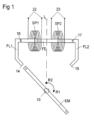
- the moving body is a shaft 10 which can rotate in the direction of arrows R1 and R2, ie clockwise or counterclockwise.
- an exciter magnet EM having a north pole N and a south pole S is assigned to it.
- the ferromagnetic element FE can be influenced by the magnetic field generated by the excitation magnet EM.
- the ferromagnetic element FE which is aligned parallel to the direction of movement of the exciter magnet, is surrounded by two sensor coils SP1 and SP2, at whose output terminals 22 and 23 the voltage pulses of the corresponding polarity generated when passing the exciter magnet EM as a result of reversal of the magnetization of the ferromagnetic element FE can be picked off.
- the second induction coil SP2 is used here as an additional sensor element for determining the triggering direction of the magnetic reversal. The triggering direction of the magnetic reversal and thus the position of the excitation magnet EM is given from the time offset of the voltage maxima of the two coils.
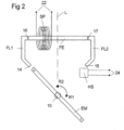
- the ferromagnetic element FE is assigned only one sensor coil SP.
- a Hall sensor HS is provided here as an additional sensor element, at whose output 24 either a signal can be picked off or not.
- the polarity is here as in 1 determined by the coil SP of the ferromagnetic element FE.
- the of The polarity determined by the Hall probe HS is irrelevant for the evaluation, but can be used as redundant information for function monitoring.
- the complete information available at time Ts to determine the polarity and direction of movement of the exciter magnet therefore consists of the data in the non-volatile memory with the signals at the output terminals of the induction coils or with the signals at the output terminals of the induction coil and the output terminals of the Hall sensor.
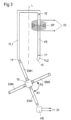
- the embodiment of the position detector according to 3 has the elements corresponding to the exemplary embodiments described above, however, to increase the resolution, four excitation magnets EM1 to EM4 arranged at right angles to one another are assigned to the shaft 10, specifically with alternating polarity. In this way, when the shaft 10 rotates, a north and a south pole alternately face the end faces of the ferromagnetic element FE via the flux guide pieces FL1 and FL2.
- the required Hall probe for determining the position of the field magnet is assigned here to the opposite ends of the field magnets EM1 to EM4.
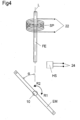
- the embodiment of the position detector according to 4 has the elements corresponding to the embodiments described above, but there are no flux guide pieces present here.
- use is primarily made of the fact that the ferromagnetic element FE is already triggered before the excitation magnet EM is in line with the ferromagnetic element FE.
- the field of vision of the Hall probe HS required for determining the position of the excitation magnet EM is adjusted in such a way that it extends approximately to the reference line L.
- the embodiment of the position detector according to figure 5 also has the elements corresponding to the embodiments described above, but here the ends of the flux guide pieces FL1 and FL2 opposite the excitation magnet are arranged over 180°.
- the Hall probe required as an additional sensor element for determining the polarity of the exciter magnet is arranged here at right angles to the reference line L through the pivot point of the shaft 10 in such a way that it still sees the corresponding poles of the exciter magnet EM when the ferromagnetic element is triggered. This always takes place at a certain angle ⁇ before entering the flux guide pieces.
- the position of the excitation magnet EM is determined by measuring the direction of magnetization reversal using the coil of the ferromagnetic element FE.
- the given variant after figure 5 gets by with the smallest possible excitation magnet EM, especially if the provided flux guide pieces are also used for flux bundling in the form of a magnetic lens.
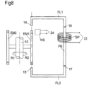
- each embodiment is shown in which the exciter magnet EM and the ferromagnetic element FE lie in one plane relative to the axis of rotation normal.
- the ferromagnetic element FE and the excitation magnet EM in separate planes - as in 7 shown - or in a plane but parallel to the axis of rotation normal - as in 8 shown - to arrange.
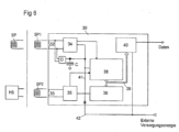
- FIG. 1 to 5 is an in 6 assigned to evaluation electronics shown as a block diagram, the input terminals 32 and 33 of which are connected to the sensor coils SP1 and SP2 or to SP and to the Hall probe HS.
- a detection logic 34 and 35 is connected downstream of the input terminals.
- a capacitor C for the energy supply is additionally connected to the input 32 via a rectifier D.
- the signals from the detection logics 34 and 35 are evaluated in a counter 38 to which a non-volatile memory 36 is assigned.
- a new counter reading is obtained, taking into account the history contained in the stored data and the information provided by the recognition logics 34 and 35 about the current position and polarity of the exciter magnet, which is then transferred to the non-volatile memory, which is generally an FRAM .
- the energy supply for the evaluation electronics is usually provided by the signals from the induction coils SP, SP1 and SP2. If only one induction coil SP is used, the Hall probe is also supplied with energy by this coil.
- the line connection 41 is part of the power supply for the evaluation electronics described above.
- the data can be picked up via the taps 39 and an interface 40 .
- a line 42 serves—if provided—to supply energy from the outside, particularly when an EEPROM is used in addition to the FRAM.
- Such an EEPROM enables the evaluation electronics in most cases to work up to the highest temperatures, because then e.g. B. important configuration data in an FRAM would be lost after a short time.
- the capacitor C in the evaluation electronics is provided for storing the supply energy obtained from the signal pulse at least until the evaluation of the signal and the process of storing the counter value in the non-volatile memory have been completed.
- the ferromagnetic element FE is characterized in that it has only one magnetic input and one magnetic output—ignoring stray fields. It is thus conceivable that there can be any parallel and/or serial interruption between the input and output, but this does not abandon the inventive idea of a single element.
Landscapes
- Physics & Mathematics (AREA)
- General Physics & Mathematics (AREA)
- Transmission And Conversion Of Sensor Element Output (AREA)
- Measurement Of Length, Angles, Or The Like Using Electric Or Magnetic Means (AREA)
- Measuring Magnetic Variables (AREA)
Claims (10)
- Détecteur de positionnement pour le relèvement des mouvements rotatoires avecau moins un aimant d'excitation (AE),un seul élément ferromagnétique (FE) avec au moins une bobine à induction (BI ou BI1) et avec au moins un élément de senseur additionnel (SA)pour la détermination des informations concernant la polarité et la position de l'aimant d'excitation (AE), étant disponibles au temps (Ts) du déclenchement d'un élément ferromagnétique (FE) comme informations complètes pour la détermination de la direction de mouvement de l'aimant d'excitation (AE).
- Détecteur de positionnement selon revendication 1 caractérisé en ce que l'élément ferromagnétique (FE) est un fil de fer à impulsion.
- Détecteur de positionnement selon les revendications 1 et 2, caractérisé en ce que la bobine à induction (BI ou BI1) sert à la mensuration de la direction du changement de l'aimantation et en connexion avec les éléments additionnels de senseur (SA) pour la détermination de la direction de déclenchement du changement de l'aimantation de l'élément ferromagnétique (FE).
- Détecteur de positionnement selon les revendications 1 à 3, caractérisé en ce que l'élément additionnel de senseur (SA) est une deuxième bobine à induction (BI2) au-dessus de l'élément ferromagnétique (FE) servant à la détermination de la direction de déclenchement du changement de l'aimantation de l'élément ferromagnétique (FE).
- Détecteur de positionnement selon les revendications 1 à 3, caractérisé en ce que l'élément additionnel de senseur (SA) est une sonde de Hall (SH) pour le dimensionnement de la polarité ou pour le relèvement de la position de l'aimant d'excitation (AE).
- Détecteur de positionnement selon les revendications 1 à 5, caractérisé en ce qu'à l'élément ferromagnétique (FE) on attribue au moins une pièce conductrice de flux (CF et/ou CF2) pour la conduction de flux et/ou pour la focalisation de flux.
- Détecteur de positionnement selon les revendications 1 à 6, caractérisé en ce que des signaux des bobines à induction (BI, BI1, BI2) pour la détermination de la position et/ou de la polarité on peut déduire l'approvisionnement énergétique pour l'électronique de l'évaluation (30).
- Détecteur de positionnement selon les revendications 1 à 7, caractérisé en ce que l'électronique de l'évaluation (30) est composée au moins d'un dispositif compteur (38), d'une mémoire non-fugace (36) et d'un condensateur (C).
- Détecteur de positionnement selon les revendications 1 à 8, caractérisé en ce que la mémoire non-fugace (36) est une mémoire FRAM et/ou EEPROM.
- Détecteur de positionnement selon une ou plusieurs de revendications précédentes, caractérisé en ce qu'une de bobines (BI / BI1) peut être renforcée par une impulsion électrique externe qui sert au déclenchement ou à la pré-tension de l'élément ferromagnétique (FE).
Applications Claiming Priority (5)
| Application Number | Priority Date | Filing Date | Title |
|---|---|---|---|
| DE10254231 | 2002-11-20 | ||
| DE10254231 | 2002-11-20 | ||
| DE10259223 | 2002-12-17 | ||
| DE10259223A DE10259223B3 (de) | 2002-11-20 | 2002-12-17 | Positionsdetektor |
| PCT/EP2003/012938 WO2004046735A1 (fr) | 2002-11-20 | 2003-11-19 | Detecteur de position |
Publications (3)
| Publication Number | Publication Date |
|---|---|
| EP1565755A1 EP1565755A1 (fr) | 2005-08-24 |
| EP1565755B1 EP1565755B1 (fr) | 2010-04-28 |
| EP1565755B2 true EP1565755B2 (fr) | 2023-07-05 |
Family
ID=32327503
Family Applications (1)
| Application Number | Title | Priority Date | Filing Date |
|---|---|---|---|
| EP03795827.9A Expired - Lifetime EP1565755B2 (fr) | 2002-11-20 | 2003-11-19 | Detecteur de position |
Country Status (5)
| Country | Link |
|---|---|
| US (1) | US7598733B2 (fr) |
| EP (1) | EP1565755B2 (fr) |
| AU (1) | AU2003298124A1 (fr) |
| CA (1) | CA2506408C (fr) |
| WO (1) | WO2004046735A1 (fr) |
Families Citing this family (30)
| Publication number | Priority date | Publication date | Assignee | Title |
|---|---|---|---|---|
| ATE522787T1 (de) | 2003-12-24 | 2011-09-15 | Walter Mehnert | Positionsdetektor |
| AU2005266797B2 (en) * | 2004-07-27 | 2009-05-21 | The Governing Council Of The University Of Toronto | Tunable magnetic switch |
| US7701756B2 (en) * | 2005-12-21 | 2010-04-20 | Governing Council Of The University Of Toronto | Magnetic memory composition and method of manufacture |
| US7288933B2 (en) * | 2005-12-22 | 2007-10-30 | Bell Helicopter Textron, Inc. | Position detecting system that self-monitors for connectivity faults |
| DE102008030201A1 (de) * | 2007-07-25 | 2009-01-29 | Dr. Johannes Heidenhain Gmbh | Drehgeber und Verfahren zu dessen Betrieb |
| DE102007039050B8 (de) | 2007-08-17 | 2024-02-15 | Avago Technologies International Sales Pte. Limited | Linearsegment- oder Umdrehungszähler mit einem ferromagnetischen Element |
| DE102007039051B8 (de) * | 2007-08-17 | 2023-09-28 | Avago Technologies International Sales Pte. Limited | Absoluter feinauflösender Segment- oder Umdrehungszähler |
| DE102008031795A1 (de) * | 2008-07-04 | 2010-01-07 | Tecpharma Licensing Ag | Verabreichungsvorrichtung mit generatorischem Sensor |
| US8405386B2 (en) * | 2009-02-17 | 2013-03-26 | Goodrich Corporation | Non-contact sensor system and method for position determination |
| US8207729B2 (en) | 2009-02-17 | 2012-06-26 | Goodrich Corporation | Non-contact sensor system and method for displacement determination |
| DE102010022154B4 (de) * | 2010-03-30 | 2017-08-03 | Avago Technologies General Ip (Singapore) Pte. Ltd. | Magnetischer Drehgeber |
| DE102011002179B4 (de) | 2011-04-19 | 2023-10-12 | Avago Technologies International Sales Pte. Limited | Verfahren und Anordnung zur Synchronisation eines Segmentzählers mit einem Feinpositionssensor |
| US9631948B2 (en) | 2012-04-15 | 2017-04-25 | Avago Technologies General Ip (Singapore) Pte. Ltd. | Method and arrangement for synchronizing a segment counter with a fine position sensor |
| EP2844955B1 (fr) | 2012-04-30 | 2016-05-11 | Fritz Kübler GmbH Zähl-und Sensortechnik | Capteur de rotation multi-tours autosuffisant en énergie et procédé de détermination sans ambiguïté la position d'un arbre capteur avec le capteur de rotation multi-tours |
| DE102012012874B4 (de) * | 2012-06-28 | 2019-06-19 | Sew-Eurodrive Gmbh & Co Kg | Anordnung zur Bestimmung einer Umdrehungsanzahl einer drehbar gelagerten Welle und Verfahren zur Bestimmung einer Umdrehungsanzahl einer drehbar gelagerten Welle |
| US9983025B2 (en) | 2013-07-14 | 2018-05-29 | Ictv Brands, Inc. | Motion sensor |
| EP2863184B1 (fr) * | 2013-10-21 | 2015-09-23 | SICK STEGMANN GmbH | Capteur de rotation avec alimentation autonome en énergie |
| CN104197965A (zh) * | 2014-09-25 | 2014-12-10 | 南京埃斯顿自动化股份有限公司 | 一种多圈旋转变压器 |
| DE102015117064B4 (de) | 2015-09-28 | 2023-06-07 | Avago Technologies International Sales Pte. Limited | Positionsdetektor |
| US10093349B2 (en) | 2016-03-02 | 2018-10-09 | Trw Automotive U.S. Llc | Monitoring of an electric motor in an electric power steering assembly |
| DE102017203679B4 (de) | 2016-05-03 | 2023-02-23 | Avago Technologies International Sales Pte. Limited | Zählsensor mit Korrekturfunktion |
| DE102017203676B4 (de) | 2016-05-31 | 2023-11-23 | Avago Technologies International Sales Pte. Limited | Magnetischer absoluter Positionssensor |
| DE102017203683B4 (de) | 2016-05-31 | 2023-02-23 | Avago Technologies International Sales Pte. Limited | Zählsensor mit korrekturfunktion |
| TWI649540B (zh) | 2017-10-26 | 2019-02-01 | 財團法人工業技術研究院 | 無電池旋轉編碼器 |
| US11079253B2 (en) | 2018-04-16 | 2021-08-03 | Avago Technologies International Sales Pte. Limited | Wiegand module and methods of forming the same |
| PL3588101T3 (pl) * | 2018-06-28 | 2021-03-22 | Baumer Germany Gmbh & Co. Kg | Komponent maszyny z czujnikiem wieganda w polu magnesu diametralnego |
| TWI843967B (zh) | 2021-09-27 | 2024-06-01 | 財團法人工業技術研究院 | 免電池旋轉檢測裝置 |
| JP7518112B2 (ja) * | 2022-02-16 | 2024-07-17 | オリエンタルモーター株式会社 | 位置検出装置 |
| CN120265948A (zh) | 2022-12-13 | 2025-07-04 | 弗瑞柏私人有限公司 | 用于确定韦根丝的磁化方向的方法及韦根传感器装置 |
| CN121127727A (zh) | 2024-03-19 | 2025-12-12 | 弗瑞柏私人有限公司 | 用于对轴的旋转运动进行检测的绝对值旋转编码器 |
Citations (7)
| Publication number | Priority date | Publication date | Assignee | Title |
|---|---|---|---|---|
| EP0484716A1 (fr) † | 1990-11-09 | 1992-05-13 | Vacuumschmelze GmbH | Capteur électromagnétique pour déterminer la vitesse et/ou la direction de rotation d'un rotor |
| DE4038284A1 (de) † | 1990-11-30 | 1992-06-04 | Brose Fahrzeugteile | Verfahren und vorrichtung zur ermittlung der position und bewegungsrichtung eines translatorisch und/oder rotatorisch bewegten teils |
| DE4233549A1 (de) † | 1992-10-01 | 1994-04-21 | Brose Fahrzeugteile | Verfahren und Vorrichtung zum Erfassen der Drehzahl und der Dreheinrichtung eines Drehantriebes |
| DE4440214A1 (de) † | 1994-11-10 | 1996-05-15 | Itt Ind Gmbh Deutsche | Drehgeber mit Hallsensoren |
| DE19543562A1 (de) † | 1994-11-22 | 1996-05-23 | Bosch Gmbh Robert | Anordnung zur berührungslosen Drehwinkelerfassung eines drehbaren Elements |
| EP0893668A1 (fr) † | 1997-07-26 | 1999-01-27 | Philips Patentverwaltung GmbH | Capteur d'angle |
| DE19847328A1 (de) † | 1998-01-28 | 1999-07-29 | Continental Teves Ag & Co Ohg | Einrichtung zur Erkennung der Drehrichtung einer Drehbewegung eines rotierenden Körpers |
Family Cites Families (13)
| Publication number | Priority date | Publication date | Assignee | Title |
|---|---|---|---|---|
| DE2817169C2 (de) | 1978-04-20 | 1986-10-23 | Robert Bosch Gmbh, 7000 Stuttgart | Einrichtung zur Abgabe von Impulsen |
| FR2456955A1 (fr) | 1979-05-16 | 1980-12-12 | Thomson Csf | Capteur magnetique et dispositif de detection de proximite comportant un tel capteur |
| DE3118768A1 (de) * | 1980-05-13 | 1982-04-01 | Robert Bosch Gmbh, 7000 Stuttgart | Vorrichtung zur erfassung der stellung oder des weges eines beweglichen bauteiles, insbesondere einer brennkraftmaschine |
| DE3317502A1 (de) * | 1983-05-13 | 1984-11-15 | Standard Elektrik Lorenz Ag, 7000 Stuttgart | Magnetischer impulsgeber mit einem wiegand-draht |
| DE3735333A1 (de) | 1987-10-19 | 1989-04-27 | Villeroy & Boch | Verfahren und vorrichtung zum herstellen keramischer fliesen mit einem streifendekor |
| JPH0274817A (ja) * | 1988-09-09 | 1990-03-14 | Nippon Steel Corp | 距離センサ |
| DE4107847C1 (en) | 1991-03-12 | 1992-09-24 | Mercedes-Benz Aktiengesellschaft, 7000 Stuttgart, De | Impulse sensor using Wiegand effect - has winding connected to single pole switch for short circuiting winding when physical quantity e.g. temp., pressure, acceleration etc. changes |
| DE4413281C2 (de) * | 1994-04-16 | 1996-02-22 | Walter Dr Mehnert | Stellungsgeber mit Datenauswerteschaltung |
| ES2118302T3 (es) | 1993-12-02 | 1998-09-16 | Walter Dr Mehnert | Detector de posicion. |
| DE4407474C2 (de) | 1994-03-07 | 2000-07-13 | Asm Automation Sensorik Messte | Drehwinkelsensor |
| WO1999054685A1 (fr) * | 1998-04-22 | 1999-10-28 | Hid Corporation | Detecteur de position lineaire a effet wiegand |
| US6265867B1 (en) * | 1999-05-19 | 2001-07-24 | Arthur D. Little, Inc. | Position encoder utilizing fluxgate sensors |
| US7113063B2 (en) * | 2002-03-18 | 2006-09-26 | Cellnet Innovations, Inc. | Rotation sensing |
-
2003
- 2003-11-19 US US10/534,396 patent/US7598733B2/en not_active Expired - Lifetime
- 2003-11-19 AU AU2003298124A patent/AU2003298124A1/en not_active Abandoned
- 2003-11-19 CA CA2506408A patent/CA2506408C/fr not_active Expired - Lifetime
- 2003-11-19 EP EP03795827.9A patent/EP1565755B2/fr not_active Expired - Lifetime
- 2003-11-19 WO PCT/EP2003/012938 patent/WO2004046735A1/fr not_active Ceased
Patent Citations (7)
| Publication number | Priority date | Publication date | Assignee | Title |
|---|---|---|---|---|
| EP0484716A1 (fr) † | 1990-11-09 | 1992-05-13 | Vacuumschmelze GmbH | Capteur électromagnétique pour déterminer la vitesse et/ou la direction de rotation d'un rotor |
| DE4038284A1 (de) † | 1990-11-30 | 1992-06-04 | Brose Fahrzeugteile | Verfahren und vorrichtung zur ermittlung der position und bewegungsrichtung eines translatorisch und/oder rotatorisch bewegten teils |
| DE4233549A1 (de) † | 1992-10-01 | 1994-04-21 | Brose Fahrzeugteile | Verfahren und Vorrichtung zum Erfassen der Drehzahl und der Dreheinrichtung eines Drehantriebes |
| DE4440214A1 (de) † | 1994-11-10 | 1996-05-15 | Itt Ind Gmbh Deutsche | Drehgeber mit Hallsensoren |
| DE19543562A1 (de) † | 1994-11-22 | 1996-05-23 | Bosch Gmbh Robert | Anordnung zur berührungslosen Drehwinkelerfassung eines drehbaren Elements |
| EP0893668A1 (fr) † | 1997-07-26 | 1999-01-27 | Philips Patentverwaltung GmbH | Capteur d'angle |
| DE19847328A1 (de) † | 1998-01-28 | 1999-07-29 | Continental Teves Ag & Co Ohg | Einrichtung zur Erkennung der Drehrichtung einer Drehbewegung eines rotierenden Körpers |
Non-Patent Citations (4)
| Title |
|---|
| "Der Wiegand-Draht, ein neuer magnetischer Sensor",Regelungstechnische Praxis 22 Jahrgang 1980, Heft 3 † |
| "Magnetische Sensoren Position, Weg, Abstand, Drehzahl, Drehwinkel", Vacuumschmelze GmbH † |
| "Simple Sensors That Need No Power", Machine Design, 26 April 1997(S. 155 ff) † |
| "Wiegand-Sensoren für Weg- und Geschwindigkeitsmessungen", Technisches Messen, 51. Jahrgang 1984, Heft 4 † |
Also Published As
| Publication number | Publication date |
|---|---|
| CA2506408A1 (fr) | 2004-06-03 |
| WO2004046735A1 (fr) | 2004-06-03 |
| AU2003298124A1 (en) | 2004-06-15 |
| CA2506408C (fr) | 2013-01-15 |
| EP1565755A1 (fr) | 2005-08-24 |
| EP1565755B1 (fr) | 2010-04-28 |
| US20060164077A1 (en) | 2006-07-27 |
| US7598733B2 (en) | 2009-10-06 |
Similar Documents
| Publication | Publication Date | Title |
|---|---|---|
| EP1565755B2 (fr) | Detecteur de position | |
| DE10259223B3 (de) | Positionsdetektor | |
| EP2515084B1 (fr) | Procédé destiné à la détermination d'un mouvement utilisant un compteur à segments et un capteur de position précis | |
| DE102007039051B4 (de) | Absoluter feinauflösender Segment- oder Umdrehungszähler | |
| EP2181308B1 (fr) | Compteur de tours à élément ferromagnétique | |
| EP2023093A2 (fr) | Encodeur et son procédé de fonctionnement | |
| EP2221587B1 (fr) | Indicateur de position magnétique absolu | |
| EP0724712B1 (fr) | Capteur d'angle de rotation | |
| EP2159547A2 (fr) | Bloc de capteurs pour un encodeur et encodeur pourvu d'un tel bloc de capteurs | |
| EP1740909A1 (fr) | Element capteur destine a un compte-tours | |
| EP0857292A1 (fr) | Dispositif de detection sans contact d'un angle de rotation | |
| DE102008051479A1 (de) | Sensorbaugruppe für einen Drehgeber und mit einer solchen Sensorbaugruppe ausgestatteter Drehgeber | |
| DE10054470C2 (de) | Drehstellungsgeber zum Erfassen einer Drehstellung | |
| EP0460291A2 (fr) | Dispositif sensible au champ magnétique ayant plusieurs détecteurs de champ magnétique | |
| EP0484716B1 (fr) | Capteur électromagnétique pour déterminer la vitesse et/ou la direction de rotation d'un rotor | |
| WO2016198061A1 (fr) | Procédé pour réinitialiser un capteur de rotation magnétorésistif et capteur de rotation correspondant | |
| DE102017203676B4 (de) | Magnetischer absoluter Positionssensor | |
| EP3924694B1 (fr) | Dispositif capteur et son procédé de fonctionnement | |
| DE19714351C2 (de) | Verfahren und Vorrichtung zum Erfassen von Gas- und Flüssigkeitsvolumina mit Volumenzählern | |
| DE102005061347A1 (de) | Anordnung zur Messung des absoluten Drehwinkels einer Welle | |
| EP1391735A1 (fr) | Circuit d'évaluation pour des capteurs à circuit oscillant | |
| DE3223924C2 (de) | Zündgeber | |
| EP0503501B1 (fr) | Appareil pour déterminer l'écartement entre deux rouleaux | |
| DE102011079631A1 (de) | Vorrichtung zur Ermittlung von Bewegungsparametern | |
| DE3326135A1 (de) | Drehgeber |
Legal Events
| Date | Code | Title | Description |
|---|---|---|---|
| PUAI | Public reference made under article 153(3) epc to a published international application that has entered the european phase |
Free format text: ORIGINAL CODE: 0009012 |
|
| 17P | Request for examination filed |
Effective date: 20050620 |
|
| AK | Designated contracting states |
Kind code of ref document: A1 Designated state(s): AT BE BG CH CY CZ DE DK EE ES FI FR GB GR HU IE IT LI LU MC NL PT RO SE SI SK TR |
|
| AX | Request for extension of the european patent |
Extension state: AL LT LV MK |
|
| DAX | Request for extension of the european patent (deleted) | ||
| 17Q | First examination report despatched |
Effective date: 20070830 |
|
| GRAP | Despatch of communication of intention to grant a patent |
Free format text: ORIGINAL CODE: EPIDOSNIGR1 |
|
| GRAS | Grant fee paid |
Free format text: ORIGINAL CODE: EPIDOSNIGR3 |
|
| GRAA | (expected) grant |
Free format text: ORIGINAL CODE: 0009210 |
|
| AK | Designated contracting states |
Kind code of ref document: B1 Designated state(s): AT BE BG CH CY CZ DE DK EE ES FI FR GB GR HU IE IT LI LU MC NL PT RO SE SI SK TR |
|
| REG | Reference to a national code |
Ref country code: GB Ref legal event code: FG4D Free format text: NOT ENGLISH |
|
| REG | Reference to a national code |
Ref country code: CH Ref legal event code: EP |
|
| REG | Reference to a national code |
Ref country code: IE Ref legal event code: FG4D Free format text: LANGUAGE OF EP DOCUMENT: GERMAN |
|
| REF | Corresponds to: |
Ref document number: 50312672 Country of ref document: DE Date of ref document: 20100610 Kind code of ref document: P |
|
| REG | Reference to a national code |
Ref country code: ES Ref legal event code: FG2A Ref document number: 2341539 Country of ref document: ES Kind code of ref document: T3 |
|
| REG | Reference to a national code |
Ref country code: CH Ref legal event code: NV Representative=s name: AMMANN PATENTANWAELTE AG BERN |
|
| REG | Reference to a national code |
Ref country code: NL Ref legal event code: T3 |
|
| PG25 | Lapsed in a contracting state [announced via postgrant information from national office to epo] |
Ref country code: SE Free format text: LAPSE BECAUSE OF FAILURE TO SUBMIT A TRANSLATION OF THE DESCRIPTION OR TO PAY THE FEE WITHIN THE PRESCRIBED TIME-LIMIT Effective date: 20100428 |
|
| REG | Reference to a national code |
Ref country code: IE Ref legal event code: FD4D |
|
| PG25 | Lapsed in a contracting state [announced via postgrant information from national office to epo] |
Ref country code: SI Free format text: LAPSE BECAUSE OF FAILURE TO SUBMIT A TRANSLATION OF THE DESCRIPTION OR TO PAY THE FEE WITHIN THE PRESCRIBED TIME-LIMIT Effective date: 20100428 Ref country code: FI Free format text: LAPSE BECAUSE OF FAILURE TO SUBMIT A TRANSLATION OF THE DESCRIPTION OR TO PAY THE FEE WITHIN THE PRESCRIBED TIME-LIMIT Effective date: 20100428 |
|
| PG25 | Lapsed in a contracting state [announced via postgrant information from national office to epo] |
Ref country code: CY Free format text: LAPSE BECAUSE OF FAILURE TO SUBMIT A TRANSLATION OF THE DESCRIPTION OR TO PAY THE FEE WITHIN THE PRESCRIBED TIME-LIMIT Effective date: 20100428 Ref country code: GR Free format text: LAPSE BECAUSE OF FAILURE TO SUBMIT A TRANSLATION OF THE DESCRIPTION OR TO PAY THE FEE WITHIN THE PRESCRIBED TIME-LIMIT Effective date: 20100729 |
|
| PG25 | Lapsed in a contracting state [announced via postgrant information from national office to epo] |
Ref country code: IE Free format text: LAPSE BECAUSE OF FAILURE TO SUBMIT A TRANSLATION OF THE DESCRIPTION OR TO PAY THE FEE WITHIN THE PRESCRIBED TIME-LIMIT Effective date: 20100428 Ref country code: PT Free format text: LAPSE BECAUSE OF FAILURE TO SUBMIT A TRANSLATION OF THE DESCRIPTION OR TO PAY THE FEE WITHIN THE PRESCRIBED TIME-LIMIT Effective date: 20100830 Ref country code: DK Free format text: LAPSE BECAUSE OF FAILURE TO SUBMIT A TRANSLATION OF THE DESCRIPTION OR TO PAY THE FEE WITHIN THE PRESCRIBED TIME-LIMIT Effective date: 20100428 Ref country code: EE Free format text: LAPSE BECAUSE OF FAILURE TO SUBMIT A TRANSLATION OF THE DESCRIPTION OR TO PAY THE FEE WITHIN THE PRESCRIBED TIME-LIMIT Effective date: 20100428 |
|
| PLBI | Opposition filed |
Free format text: ORIGINAL CODE: 0009260 |
|
| PG25 | Lapsed in a contracting state [announced via postgrant information from national office to epo] |
Ref country code: SK Free format text: LAPSE BECAUSE OF FAILURE TO SUBMIT A TRANSLATION OF THE DESCRIPTION OR TO PAY THE FEE WITHIN THE PRESCRIBED TIME-LIMIT Effective date: 20100428 Ref country code: RO Free format text: LAPSE BECAUSE OF FAILURE TO SUBMIT A TRANSLATION OF THE DESCRIPTION OR TO PAY THE FEE WITHIN THE PRESCRIBED TIME-LIMIT Effective date: 20100428 Ref country code: CZ Free format text: LAPSE BECAUSE OF FAILURE TO SUBMIT A TRANSLATION OF THE DESCRIPTION OR TO PAY THE FEE WITHIN THE PRESCRIBED TIME-LIMIT Effective date: 20100428 |
|
| PLAX | Notice of opposition and request to file observation + time limit sent |
Free format text: ORIGINAL CODE: EPIDOSNOBS2 |
|
| 26 | Opposition filed |
Opponent name: ASM AUTOMATION SENSORIK MESSTECHNIK GMBH Effective date: 20110126 |
|
| BERE | Be: lapsed |
Owner name: THEIL, THOMAS Effective date: 20101130 Owner name: MEHNERT, WALTER, DR. Effective date: 20101130 |
|
| PG25 | Lapsed in a contracting state [announced via postgrant information from national office to epo] |
Ref country code: MC Free format text: LAPSE BECAUSE OF NON-PAYMENT OF DUE FEES Effective date: 20101130 |
|
| PLAF | Information modified related to communication of a notice of opposition and request to file observations + time limit |
Free format text: ORIGINAL CODE: EPIDOSCOBS2 |
|
| PLBB | Reply of patent proprietor to notice(s) of opposition received |
Free format text: ORIGINAL CODE: EPIDOSNOBS3 |
|
| PG25 | Lapsed in a contracting state [announced via postgrant information from national office to epo] |
Ref country code: BE Free format text: LAPSE BECAUSE OF NON-PAYMENT OF DUE FEES Effective date: 20101130 |
|
| PG25 | Lapsed in a contracting state [announced via postgrant information from national office to epo] |
Ref country code: BG Free format text: LAPSE BECAUSE OF FAILURE TO SUBMIT A TRANSLATION OF THE DESCRIPTION OR TO PAY THE FEE WITHIN THE PRESCRIBED TIME-LIMIT Effective date: 20100428 Ref country code: HU Free format text: LAPSE BECAUSE OF FAILURE TO SUBMIT A TRANSLATION OF THE DESCRIPTION OR TO PAY THE FEE WITHIN THE PRESCRIBED TIME-LIMIT Effective date: 20101029 Ref country code: LU Free format text: LAPSE BECAUSE OF NON-PAYMENT OF DUE FEES Effective date: 20101119 |
|
| PG25 | Lapsed in a contracting state [announced via postgrant information from national office to epo] |
Ref country code: TR Free format text: LAPSE BECAUSE OF FAILURE TO SUBMIT A TRANSLATION OF THE DESCRIPTION OR TO PAY THE FEE WITHIN THE PRESCRIBED TIME-LIMIT Effective date: 20100428 |
|
| RDAF | Communication despatched that patent is revoked |
Free format text: ORIGINAL CODE: EPIDOSNREV1 |
|
| APAH | Appeal reference modified |
Free format text: ORIGINAL CODE: EPIDOSCREFNO |
|
| APBM | Appeal reference recorded |
Free format text: ORIGINAL CODE: EPIDOSNREFNO |
|
| APBP | Date of receipt of notice of appeal recorded |
Free format text: ORIGINAL CODE: EPIDOSNNOA2O |
|
| APBQ | Date of receipt of statement of grounds of appeal recorded |
Free format text: ORIGINAL CODE: EPIDOSNNOA3O |
|
| PG25 | Lapsed in a contracting state [announced via postgrant information from national office to epo] |
Ref country code: BG Free format text: LAPSE BECAUSE OF FAILURE TO SUBMIT A TRANSLATION OF THE DESCRIPTION OR TO PAY THE FEE WITHIN THE PRESCRIBED TIME-LIMIT Effective date: 20100728 |
|
| REG | Reference to a national code |
Ref country code: FR Ref legal event code: PLFP Year of fee payment: 13 |
|
| REG | Reference to a national code |
Ref country code: DE Ref legal event code: R082 Ref document number: 50312672 Country of ref document: DE Representative=s name: DILG, HAEUSLER, SCHINDELMANN PATENTANWALTSGESE, DE Ref country code: DE Ref legal event code: R082 Ref document number: 50312672 Country of ref document: DE Representative=s name: DILG HAEUSLER SCHINDELMANN PATENTANWALTSGESELL, DE Ref country code: DE Ref legal event code: R082 Ref document number: 50312672 Country of ref document: DE |
|
| REG | Reference to a national code |
Ref country code: DE Ref legal event code: R082 Ref document number: 50312672 Country of ref document: DE Representative=s name: DILG, HAEUSLER, SCHINDELMANN PATENTANWALTSGESE, DE |
|
| REG | Reference to a national code |
Ref country code: FR Ref legal event code: PLFP Year of fee payment: 14 |
|
| RAP2 | Party data changed (patent owner data changed or rights of a patent transferred) |
Owner name: AVAGO TECHNOLOGIES GENERAL IP (SINGAPORE) PTE. LTD |
|
| RIN2 | Information on inventor provided after grant (corrected) |
Inventor name: THEIL, THOMAS Inventor name: MEHNERT, WALTER |
|
| PLAB | Opposition data, opponent's data or that of the opponent's representative modified |
Free format text: ORIGINAL CODE: 0009299OPPO |
|
| REG | Reference to a national code |
Ref country code: FR Ref legal event code: PLFP Year of fee payment: 15 |
|
| R26 | Opposition filed (corrected) |
Opponent name: ASM AUTOMATION SENSORIK MESSTECHNIK GMBH Effective date: 20110126 |
|
| REG | Reference to a national code |
Ref country code: FR Ref legal event code: PLFP Year of fee payment: 16 |
|
| APBU | Appeal procedure closed |
Free format text: ORIGINAL CODE: EPIDOSNNOA9O |
|
| RAP2 | Party data changed (patent owner data changed or rights of a patent transferred) |
Owner name: AVAGO TECHNOLOGIES INTERNATIONAL SALES PTE. LIMITE |
|
| REG | Reference to a national code |
Ref country code: DE Ref legal event code: R082 Ref document number: 50312672 Country of ref document: DE Representative=s name: DILG HAEUSLER SCHINDELMANN PATENTANWALTSGESELL, DE Ref country code: DE Ref legal event code: R081 Ref document number: 50312672 Country of ref document: DE Owner name: AVAGO TECHNOLOGIES INTERNATIONAL SALES PTE. LT, SG Free format text: FORMER OWNERS: MEHNERT, WALTER, DR., 85521 OTTOBRUNN, DE; THEIL, THOMAS, DR., 85258 WEICHS, DE Ref country code: DE Ref legal event code: R082 Ref document number: 50312672 Country of ref document: DE Representative=s name: DILG, HAEUSLER, SCHINDELMANN PATENTANWALTSGESE, DE |
|
| PGFP | Annual fee paid to national office [announced via postgrant information from national office to epo] |
Ref country code: NL Payment date: 20221220 Year of fee payment: 20 Ref country code: GB Payment date: 20221221 Year of fee payment: 20 Ref country code: FR Payment date: 20221219 Year of fee payment: 20 Ref country code: ES Payment date: 20221201 Year of fee payment: 20 Ref country code: DE Payment date: 20220616 Year of fee payment: 20 Ref country code: AT Payment date: 20221222 Year of fee payment: 20 |
|
| PGFP | Annual fee paid to national office [announced via postgrant information from national office to epo] |
Ref country code: CH Payment date: 20221228 Year of fee payment: 20 |
|
| PGFP | Annual fee paid to national office [announced via postgrant information from national office to epo] |
Ref country code: IT Payment date: 20221220 Year of fee payment: 20 |
|
| PUAH | Patent maintained in amended form |
Free format text: ORIGINAL CODE: 0009272 |
|
| STAA | Information on the status of an ep patent application or granted ep patent |
Free format text: STATUS: PATENT MAINTAINED AS AMENDED |
|
| 27A | Patent maintained in amended form |
Effective date: 20230705 |
|
| AK | Designated contracting states |
Kind code of ref document: B2 Designated state(s): AT BE BG CH CY CZ DE DK EE ES FI FR GB GR HU IE IT LI LU MC NL PT RO SE SI SK TR |
|
| REG | Reference to a national code |
Ref country code: DE Ref legal event code: R102 Ref document number: 50312672 Country of ref document: DE |
|
| REG | Reference to a national code |
Ref country code: DE Ref legal event code: R082 Ref document number: 50312672 Country of ref document: DE Representative=s name: KILIAN KILIAN & PARTNER MBB PATENTANWAELTE, DE |
|
| REG | Reference to a national code |
Ref country code: DE Ref legal event code: R071 Ref document number: 50312672 Country of ref document: DE |
|
| PG25 | Lapsed in a contracting state [announced via postgrant information from national office to epo] |
Ref country code: NL Free format text: LAPSE BECAUSE OF FAILURE TO SUBMIT A TRANSLATION OF THE DESCRIPTION OR TO PAY THE FEE WITHIN THE PRESCRIBED TIME-LIMIT Effective date: 20100428 |
|
| REG | Reference to a national code |
Ref country code: CH Ref legal event code: PL |
|
| REG | Reference to a national code |
Ref country code: GB Ref legal event code: PE20 Expiry date: 20231118 |
|
| REG | Reference to a national code |
Ref country code: AT Ref legal event code: MK07 Ref document number: 466287 Country of ref document: AT Kind code of ref document: T Effective date: 20231119 |
|
| PG25 | Lapsed in a contracting state [announced via postgrant information from national office to epo] |
Ref country code: GB Free format text: LAPSE BECAUSE OF EXPIRATION OF PROTECTION Effective date: 20231118 |
|
| PG25 | Lapsed in a contracting state [announced via postgrant information from national office to epo] |
Ref country code: ES Free format text: LAPSE BECAUSE OF FAILURE TO SUBMIT A TRANSLATION OF THE DESCRIPTION OR TO PAY THE FEE WITHIN THE PRESCRIBED TIME-LIMIT Effective date: 20230705 |
|
| PG25 | Lapsed in a contracting state [announced via postgrant information from national office to epo] |
Ref country code: GB Free format text: LAPSE BECAUSE OF EXPIRATION OF PROTECTION Effective date: 20231118 Ref country code: ES Free format text: LAPSE BECAUSE OF FAILURE TO SUBMIT A TRANSLATION OF THE DESCRIPTION OR TO PAY THE FEE WITHIN THE PRESCRIBED TIME-LIMIT Effective date: 20230705 |