EP1565668B1 - Schreibenbremse mit einer nachstelleinrichtung, insbesondere für ein nutzfahrzeug - Google Patents
Schreibenbremse mit einer nachstelleinrichtung, insbesondere für ein nutzfahrzeug Download PDFInfo
- Publication number
- EP1565668B1 EP1565668B1 EP03767561A EP03767561A EP1565668B1 EP 1565668 B1 EP1565668 B1 EP 1565668B1 EP 03767561 A EP03767561 A EP 03767561A EP 03767561 A EP03767561 A EP 03767561A EP 1565668 B1 EP1565668 B1 EP 1565668B1
- Authority
- EP
- European Patent Office
- Prior art keywords
- brake
- disc
- disc brake
- spring lock
- lock washer
- Prior art date
- Legal status (The legal status is an assumption and is not a legal conclusion. Google has not performed a legal analysis and makes no representation as to the accuracy of the status listed.)
- Expired - Lifetime
Links
Images

Classifications
-
- F—MECHANICAL ENGINEERING; LIGHTING; HEATING; WEAPONS; BLASTING
- F16—ENGINEERING ELEMENTS AND UNITS; GENERAL MEASURES FOR PRODUCING AND MAINTAINING EFFECTIVE FUNCTIONING OF MACHINES OR INSTALLATIONS; THERMAL INSULATION IN GENERAL
- F16D—COUPLINGS FOR TRANSMITTING ROTATION; CLUTCHES; BRAKES
- F16D65/00—Parts or details
- F16D65/38—Slack adjusters
- F16D65/40—Slack adjusters mechanical
- F16D65/52—Slack adjusters mechanical self-acting in one direction for adjusting excessive play
- F16D65/56—Slack adjusters mechanical self-acting in one direction for adjusting excessive play with screw-thread and nut
- F16D65/567—Slack adjusters mechanical self-acting in one direction for adjusting excessive play with screw-thread and nut for mounting on a disc brake
- F16D65/568—Slack adjusters mechanical self-acting in one direction for adjusting excessive play with screw-thread and nut for mounting on a disc brake for synchronous adjustment of actuators arranged in parallel
-
- F—MECHANICAL ENGINEERING; LIGHTING; HEATING; WEAPONS; BLASTING
- F16—ENGINEERING ELEMENTS AND UNITS; GENERAL MEASURES FOR PRODUCING AND MAINTAINING EFFECTIVE FUNCTIONING OF MACHINES OR INSTALLATIONS; THERMAL INSULATION IN GENERAL
- F16D—COUPLINGS FOR TRANSMITTING ROTATION; CLUTCHES; BRAKES
- F16D55/00—Brakes with substantially-radial braking surfaces pressed together in axial direction, e.g. disc brakes
- F16D2055/0004—Parts or details of disc brakes
- F16D2055/0062—Partly lined, i.e. braking surface extending over only a part of the disc circumference
Definitions
- the present invention relates to a disc brake, in particular for a commercial vehicle, according to the preamble of claim 1.
- the application device is coupled to a crossbar, in which preferably two adjusting spindles are mounted, each having a pressure piece for receiving a brake shoe, the is pressed in the case of operation to a brake disc.
- the two adjusting spindles are provided with an external thread and screwed into a respectively assigned threaded bore of the traverse.
- the brake shoe is so far delivered by turning the adjusting spindles in the threaded holes in case of wear of the brake pad, that a clearance between the brake pad and the brake disc remains substantially constant.
- securing elements are used, the rotationally inhibiting acting on the adjusting spindles, so that said unintentional adjustment of the adjusting spindles is prevented.
- the securing elements are rubbing against the adjusting spindle or parts thereof.
- the frictional force is such that, at a certain torque to be applied by the adjusting device, the rotation of the adjusting spindles is easily possible, this torque being greater than such, as may result from the vibration forces during driving.
- a known securing element consists of a secondary seal, which is arranged in the pressure piece facing the end region of an adjusting spindle and engages lockingly into the adjusting spindle.
- the function of the rotational inhibition, the secondary seal or the cross into the adjusting spindle part of a plastic which can be pulled especially by the frictional heat generated during braking affected.
- the present invention is therefore the object of a disc brake of the generic type to further develop so that with simple design means the reliability of the rotational inhibition of the adjusting spindle improves and the overall reliability is increased.
- the arrangement of the securing element in the form of the spring ring is substantially freely selectable, so that the spring ring outside a Area can be placed, which is acted upon by the heat generated during braking. Material damaging influences can thereby practically no longer occur or negligible, resulting in a relation to the prior art significantly improved safety.
- the spring ring made of metal, instead of plastic as before. Due to the heat insensitivity of the metal compared to the previously used plastic, the securing element can be provided practically at any suitable point of the functional area, without resulting in service life disadvantages. In addition, the conditional by the anti-rotation frictional forces wear of the fuse element is negligibly small, so that overall results in a significant improvement in reliability in continuous operation.
- the clamping effect itself is definable, by the nature and design of the spring washers and the defined mounting position between the components to be clamped.
- the required clamping force of the spring ring can be achieved by geometry changes, but also by appropriate choice of material and is exactly predeterminable.
- the spring ring in its contour wave-shaped, so that a part of the forming, radially aligned dome at the bottom of the annular groove and the other part of the thread of the associated component, ie the adjusting spindle or the threaded hole, is applied.
- FIG 1 is a disc brake, in particular for a commercial vehicle, shown, which has a brake caliper 2 in its basic structure, which comprises a ventilated brake disc 1 which is fixed to an axle, not shown, of the utility vehicle.
- the caliper 2 is fixed to a brake carrier 6 of the commercial vehicle, based on the brake disc 1, axially displaceable.
- fastening elements 5 are provided, each having a sliding bushing 7 and a guide rail 8.
- the sliding bushes 7 are immovably connected to the caliper 2, while the guide rails 8 are screwed into the brake carrier 6, so that the sliding bushes 7 are mounted axially displaceable together with the brake caliper 2 on the extent stationary guide rails 8.
- the brake disc 1 with brake pads 9 for braking in operative connection can be brought.
- the brake pads 9 are pressed against the brake disc 1 during braking.
- a brake application device 11 is arranged on one side of the brake caliper 2, of which only a part can be seen in the present exemplary embodiment and which is connected to a cross member 10.
- the rotation of an adjusting spindle 12 caused by the adjusting device can be transmitted by a synchronization device to the other adjusting spindle, so that it is rotated by the same angular amount with the result that both adjusting spindles 12 are moved by exactly the same axial distance.
- securing elements are each in Form of a spring ring 14 is provided, the rotationally restraining rests either on the thread of the adjusting spindle 12 or the threaded bore 16.
- the upper adjusting spindle 12 has a circumferential annular groove 15 in which the spring ring 14 rests.
- the annular groove 15 is formed in the region of the lower adjusting spindle 12 by a recess in the threaded bore 16, in which the spring ring 14 rests and frictionally abuts the external thread of the adjusting spindle 12.
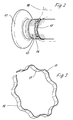
- FIG. 2 An enlarged view is shown as a schematic section of the traverse 10 in FIG. 2, this illustration corresponding to the region of the lower adjusting spindle 12 according to FIG.
- the spring ring 14 has a wavy contour whose peaks 17 alternately rest on the bottom of the annular groove 15 and the external thread of the adjusting spindle 12.
- the spring ring 14 which is preferably formed from a sheet steel strip, slotted, so that the spring forces can be radially effective.
- the annular groove 15, which preferably runs without pitch, is adapted in its width to the width of the spring ring 14, so that this rests axially 29iebegeschreibt.
Landscapes
- Engineering & Computer Science (AREA)
- General Engineering & Computer Science (AREA)
- Mechanical Engineering (AREA)
- Braking Arrangements (AREA)
Description
- Die vorliegende Erfindung betrifft eine Scheibenbremse, insbesondere für ein Nutzfahrzeug, gemäß dem Oberbegriff des Anspruchs 1.
- Bei einer derartigen Scheibenbremse, wie sie beispielsweise aus der DE 94 22 342 U1 bekannt ist und die üblicherweise druckluftbetätigbar ist, ist die Zuspannvorrichtung mit einer Traverse gekoppelt, in der vorzugsweise zwei Stellspindeln gelagert sind, die jeweils ein Druckstück zur Aufnahme einer Bremsbacke aufweisen, die im Funktionsfall an eine Bremsscheibe angedrückt wird.
- Die beiden Stellspindeln sind mit einem Außengewinde versehen und in eine jeweils zugeordnete Gewindebohrung der Traverse eingeschraubt.
- Mittels einer Nachstelleinrichtung, die einer Stellspindel zugeordnet ist, und einem Mitnehmer der anderen Stellspindel wird durch Verdrehen der Stellspindeln in den Gewindebohrungen bei Verschleiß des Bremsbelages die Bremsbacke so weit zugestellt, daß ein Lüftspiel zwischen dem Bremsbelag und der Bremsscheibe im wesentlichen immer konstant bleibt.
- Um zu verhindern, daß durch Erschütterungen während des Fahrbetriebs die Stellspindeln ihre Lage und somit den Abstand zwischen dem Bremsbelag und der Scheibenbremse, also das Lüftspiel, verändern, werden Sicherungselemente eingesetzt, die drehhemmend auf die Stellspindeln einwirken, so daß die genannte unbeabsichtigte Verstellung der Stellspindeln verhindert wird. Dabei liegen die Sicherungselemente reibend an der Stellspindel oder Teilen davon an.
- Die Reibkraft ist so bemessen, daß bei einem durch die Nachstelleinrichtung aufzubringenden bestimmten Drehmoment die Drehung der Stellspindeln problemlos möglich ist, wobei dieses Drehmoment größer ist als ein solches, wie es sich aus den Erschütterungskräften im Fahrbetrieb ergeben kann.
- Ein bekanntes Sicherungselement besteht aus einer Sekundärdichtung, die in dem dem Druckstück zugewandten Endbereich einer Stellspindel angeordnet ist und sichernd in die Stellspindel eingreift.
- Unter anderem zur Funktion der Drehhemmung besteht die Sekundärdichtung bzw. das in die Stellspindel greifende Teil aus einem Kunststoff, der vor allem durch die beim Bremsen entstehende Reibwärme in Mitleidenschaft gezogen werden kann.
- Dies trifft gleichermaßen auf eine ebenfalls aus Kunststoff bestehende Hülse zu, durch die eine Druckfeder vorspannbar ist, die sich andererseits an dem genannten Mitnehmer der zweiten Stellspindel abstützt, wodurch in diesem Bereich eine Drehhemmung erreicht wird,
- Durch die konstruktionsbedingt unterschiedlichen Eingriffe im Sinne einer Drehhemmung beider Sicherungselemente ist überdies eine für beide gleiche Reibwerteinstellung praktisch nicht möglich, woraus sich ebenfalls Probleme sowohl beim Nachstellen wie auch bei der Sicherung der beiden Stellspindeln ergeben können.
- Der vorliegenden Erfindung liegt daher die Aufgabe zugrunde, eine Scheibenbremse der gattungsgemäßen Art so weiter zu entwicleln, daß mit konstruktiv einfachen Mitteln die Zuverlässigkeit der Drehhemmung der Stellspindel verbessert und die Betriebssicherheit insgesamt erhöht wird.
- Diese Aufgabe wird durch eine Scheibenbremse gelöst, die die Merkmale des Anspruchs 1 aufweist.
- Innerhalb der Gewindebohrung bzw. des Eingriffsbereiches der Gewindespindel in das Gewinde der Gewindebohrung ist die Anordnung des Sicherungselementes in Form des Federringes im wesentlichen frei wählbar, so daß der Federring außerhalb eines Bereiches plaziert werden kann, der von der bei einer Bremsung entstehenden Wärme beaufschlagt wird. Materialschädigende Einflüsse können dadurch praktisch nicht mehr oder unwesentlich auftreten, wodurch sich eine gegenüber dem Stand der Technik erheblich verbesserte Sicherheit ergibt.
- In vorteilhafter Weise besteht der Federring aus Metall, statt wie bisher aus Kunststoff. Aufgrund der Wärmeunempfindlichkeit des Metalls gegenüber dem bisher eingesetzten Kunststoff kann das Sicherungselement praktisch an jeder geeigneten Stelle des Funktionsbereiches vorgesehen sein, ohne daß sich Standzeitnachteile ergeben. Darüber hinaus ist der durch die drehhemmend wirkenden Reibkräfte bedingte Verschleiß des Sicherungselementes vernachlässigbar klein, so daß sich insgesamt eine wesentliche Verbesserung der Funktionssicherheit im Dauerbetrieb ergibt.
- Da nun eine exakte Positionierung der Sicherungselemente möglich ist sowie eine genau gleiche Ausbildung insbesondere hinsichtlich Material und Form der Federringe, wird für beide Stellspindeln ein gleich großes Klemmoment wirksam.
- Die Klemmwirkung selbst ist definierbar, und zwar durch die Art und Ausführung der Federringe sowie die definierte Einbaulage zwischen den zu verspannenden Bauteilen.
- Die Drehhemmung der Gewindespindeln erfolgt gleichmäßig über den gesamten Umfang, ohne Angriff auf die Gewindeflanken, wodurch sich eine schonende Klemmung ergibt.
- Die erforderliche Klemmkraft des Federringes kann durch Geometrieänderungen, aber auch durch entsprechende Materialauswahl erreicht werden und ist exakt vorbestimmbar.
- Nach einem weiteren Gedanken der Erfindung ist vorgesehen, den Federring in seiner Kontur wellenförmig zu gestalten, so daß ein Teil der sich bildenden ,radial ausgerichteten Kuppen am Grund der Ringnut und der andere Teil am Gewinde des zugeordneten Bauteiles, also der Stellspindel oder der Gewindebohrung, anliegt.
- Da der Federring über den ganzen Umfang reibend anliegt, ist eine Verdrehsicherung für den Federring nicht erforderlich.
- Im übrigen ist die Herstellung des Federringes, dessen Montage sowie das Einbringen der Ringnut sehr einfach und kostengünstig möglich. Auch ein Auswechseln des Federringes gestaltet sich sehr einfach, so daß sich insgesamt eine Kostenoptimierung ergibt, die insbesondere deshalb als besonders vorteilhaft angesehen werden muß, als solche Scheibenbremsen in großen Stückzahlen Verwendung finden.
- Weitere vorteilhafte Ausbildungen der Erfindung sind in den Unteransprüchen gekennzeichnet.
- Ausführungsbeispiele der Erfindung werden nachfolgend anhand der beigefügten Zeichnungen beschrieben.
- Es zeigen:
- Figur 1
- eine erfindungsgemäße Scheibenbremse in einer teilweise geschnittenen Draufsicht,
- Figur 2
- eine Einzelheit der Scheibenbremse in einer perspektivischen Ansicht,
- Figur 3
- ein Sicherungselement nach der Erfindung ebenfalls in perspektivischer Darstellung.
- In der Figur 1 ist eine Scheibenbremse, insbesondere für ein Nutzfahrzeug, dargestellt, die in ihrem Grundaufbau einen Bremssattel 2 aufweist, der eine innenbelüftete Bremsscheibe 1 umfaßt, die an einer nicht dargestellten Achse des Nutzfahrzeuges befestigt ist.
- Der Bremssattel 2 ist an einem Bremsträger 6 des Nutzfahrzeuges, bezogen auf die Bremsscheibe 1, axial verschiebbar festgelegt.
- Hierzu sind Befestigungselemente 5 vorgesehen, die jeweils eine Gleitbuchse 7 sowie einen Führungsholm 8 aufweisen.
- Die Gleitbuchsen 7 sind unverrückbar mit dem Bremssattel 2 verbunden, während die Führungsholme 8 in den Bremsträger 6 eingeschraubt sind, so daß die Gleitbuchsen 7 zusammen mit dem Bremssattel 2 auf den insoweit ortsfesten Führungsholmen 8 axial verschiebbar gelagert sind.
- Wie weiter in der Figur 1 erkennbar ist, ist die Bremsscheibe 1 mit Bremsbelägen 9 zur Abbremsung in Wirkverbindung bringbar. Hierzu werden die Bremsbeläge 9 bei Bremsungen gegen die Bremsscheibe 1 gedrückt.
- Zur Auslösung eines Bremsvorgangs ist an einer Seite des Bremssattels 2 eine Zuspannvorrichtung 11 angeordnet, von der im vorliegenden Ausführungsbeispiel nur ein Teil erkennbar ist und die an eine Traverse 10 angeschlossen ist.
- In diese Traverse 10 sind zwei parallel und mit Abstand zueinander verlaufende, ein Außengewinde aufweisende Stellspindeln 12 eingeschraubt, die an einem Ende jeweils ein Druckstück 13 tragen, an denen einer der beiden Bremsbeläge 9 befestigt ist.
- Mittels einer nicht dargestellten, mit mindestens einer der beiden Stellspindeln 12 gekoppelten Nachstelleinrichtung wird bei jeder Betätigung der Zuspannvorrichtung 11 erreicht, daß sich das infolge eines Belagverschleißes ändernde Lüftspiel konstant bleibt, d. h., die Stellspindeln 12 werden durch Drehung entsprechend axial verschoben.
- Dabei kann die durch die Nachstelleinrichtung bewirkte Drehung einer Stellspindel 12 durch eine Synchronisationseinrichtung auf die andere Stellspindel übertragen werden, so daß diese um den gleichen Winkelbetrag gedreht wird mit der Folge, daß beide Stellspindeln 12 um exakt die gleiche axiale Strecke verfahren werden.
- Um zu verhindern, daß sich während des Fahrbetriebs, beispielsweise durch Erschütterung, die Stellspindeln 12 unbeabsichtigt verdrehen und somit das Lüftspiel entsprechend in unerwünschter Weise verändert wird, sind Sicherungselemente jeweils in Form eines Federringes 14 vorgesehen, der drehhemmend entweder an dem Gewinde der Stellspindel 12 oder der Gewindebohrung 16 anliegt.
- Beide Ausführungsmöglichkeiten sind in der Figur 1 erkennbar. Dabei ist zu sehen, daß die obere Stellspindel 12 eine umlaufende Ringnut 15 aufweist, in der der Federring 14 einliegt. Hingegen ist die Ringnut 15 im Bereich der unteren Stellspindel 12 durch einen Einstich in die Gewindebohrung 16 gebildet, in der der Federring 14 einliegt und reibend am Außengewinde der Stellspindel 12 anliegt.
- Eine vergrößerte Darstellung ist als schematischer Ausschnitt der Traverse 10 in der Figur 2 gezeigt, wobei diese Darstellung dem Bereich der unteren Stellspindel 12 nach Figur 1 entspricht.
- Darin ist ebenso wie in der Figur 3 zu erkennen, daß das der Federring 14 eine wellenförmige Kontur aufweist, deren Kuppen 17 wechselweise am Grund der Ringnut 15 und am Außengewinde der Stellspindel 12 anliegen.
- Wie weiter in der Figur 3 zu sehen ist, ist der Federring 14, der vorzugsweise aus einem Stahlblechstreifen geformt ist, geschlitzt, so daß die Federkräfte radial wirksam werden können.
- Selbstverständlich sind neben der gezeigten Form des Federringes 14 auch andere Formen denkbar, insbesondere andere Konturen.
- Die Ringnut 15, die vorzugsweise steigungsfrei verläuft, ist in ihrer Breite der Breite des Federringes 14 angepaßt, so daß dieser axial verschiebegesichert einliegt.
-
- 1
- Bremssscheibe
- 2
- Bremssattel 3 4
- 5
- Befestigungselement
- 6
- Bremsträger
- 7
- Gleitbuchse
- 8
- Führungsholm
- 9
- Bremsbelag
- 10
- Traverse
- 11
- Zuspannvorrichtung
- 12
- Stellspindel
- 13
- Druckstück
- 14
- Sicherungselement
- 15
- Ringnut
- 16
- Gewindebohrung
- 17
- Hügel
Claims (10)
- Scheibenbremse, insbesondere für ein Nutzfahrzeug, mit einem eine Bremsscheibe (1) umfassenden Bremssattel (2), der an einem Bremsträger (6), bezogen auf die Bremsscheibe (1), axial verschiebbar befestigt ist und an dessen einer Seite eine Zuspannvorrichtung (11) angeordnet ist, mit einem verschieblichen Element, insbesondere einer Traverse (10), das mindestens eine Gewindebohrung (16) aufweist, in die eine Stellspindel (12) eingeschraubt ist, die ein Druckstück (13) trägt, mit dem eine Bremsbacke (9) gegen die Bremsscheibe (1) preßbar ist, mit einer mit der Stellspindel (12) in Wirkverbindung stehenden Nachstelleinrichtung, mit der eine verschleißbedingte Änderung eines Lüftspiels zwischen der Bremsbacke (9) und der Bremsscheibe (1) im wesentlichen ausgleichbar ist, und mit einem bis zu einem bestimmten Drehmoment drehhemmend auf die Stellspindel (12) wirkenden Sicherungselement, dadurch gekennzeichnet, daß das Sicherungselement aus einem Federring (14) besteht, der in einer Ringnut (15) der Gewindebohrung (16) oder der Stellspindel (12) einliegt und sich federnd an dem gegenüber liegenden Gewinde abstützt.
- Scheibenbremse nach Anspruch 1, dadurch gekennzeichnet, daß der Federring aus Metall besteht.
- Scheibenbremse nach Anspruch 2, dadurch gekennzeichnet, daß der Federring (14) als Stahlfeder ausgebildet ist.
- Scheibenbremse nach einem der Ansprüche 1 bis 3, dadurch gekennzeichnet, daß der Federring (14) eine wellenförmige Kontur aufweist.
- Scheibenbremse nach einem der Ansprüche 1 bis 4, dadurch gekennzeichnet, daß der Federring (14) aus einem streifenförmigen Federmaterial, vorzugsweise Federblech, geformt ist.
- Scheibenbremse nach Anspruch 1, dadurch gekennzeichnet, daß die Ringnut (15) steigungsfrei ausgebildet ist.
- Scheibenbremse nach Anspruch 1, dadurch gekennzeichnet, daß die Ringnut (15) in ihrer Breite etwa der Breite des Federringes (14) entspricht.
- Scheibenbremse nach einem der Ansprüche 1 bis 7, dadurch gekennzeichnet, daß der Federring (14) in seiner Geometrie, Dimensionierung und Materialauswahl abhängig von der auf die Stellspindel (12) aufzubringenden Klemmkraft bestimmt ist.
- Scheibenbremse nach Anspruch 1, bei der zwei parallel und mit Abstand zueinander verlaufende Stellspindeln (12) vorgesehen sind, dadurch gekennzeichnet, daß jeder Stellspindel (12) ein Federring (14) zugeordnet ist.
- Scheibenbremse nach Anspruch 9, dadurch gekennzeichnet, daß die Federringe (14) in Form, Material und Dimensionierung gleich sind.
Applications Claiming Priority (3)
| Application Number | Priority Date | Filing Date | Title |
|---|---|---|---|
| DE10253642 | 2002-11-18 | ||
| DE10253642A DE10253642A1 (de) | 2002-11-18 | 2002-11-18 | Scheibenbremse, insbesondere für ein Nutzfahrzeug |
| PCT/EP2003/012841 WO2004046579A1 (de) | 2002-11-18 | 2003-11-17 | Scheibenbremse mit einer nachstelleinrichtung, insbesondere für ein nutzfahrzeug |
Publications (2)
| Publication Number | Publication Date |
|---|---|
| EP1565668A1 EP1565668A1 (de) | 2005-08-24 |
| EP1565668B1 true EP1565668B1 (de) | 2006-10-25 |
Family
ID=32240124
Family Applications (1)
| Application Number | Title | Priority Date | Filing Date |
|---|---|---|---|
| EP03767561A Expired - Lifetime EP1565668B1 (de) | 2002-11-18 | 2003-11-17 | Schreibenbremse mit einer nachstelleinrichtung, insbesondere für ein nutzfahrzeug |
Country Status (6)
| Country | Link |
|---|---|
| US (1) | US20060144652A1 (de) |
| EP (1) | EP1565668B1 (de) |
| AT (1) | ATE343740T1 (de) |
| AU (1) | AU2003292036A1 (de) |
| DE (2) | DE10253642A1 (de) |
| WO (1) | WO2004046579A1 (de) |
Cited By (4)
| Publication number | Priority date | Publication date | Assignee | Title |
|---|---|---|---|---|
| DE102014105418A1 (de) * | 2014-04-16 | 2015-10-22 | Knorr-Bremse Systeme für Nutzfahrzeuge GmbH | Scheibenbremse für ein Nutzfahrzeug |
| DE102014106535A1 (de) * | 2014-05-09 | 2015-11-12 | Knorr-Bremse Systeme für Nutzfahrzeuge GmbH | Scheibenbremse für ein Nutzfahrzeug |
| DE102014115767A1 (de) * | 2014-10-30 | 2016-05-04 | Knorr-Bremse Systeme für Nutzfahrzeuge GmbH | Scheibenbremse für ein Nutzfahrzeug |
| DE102014019111A1 (de) * | 2014-12-19 | 2016-06-23 | Knorr-Bremse Systeme für Nutzfahrzeuge GmbH | Scheibenbremse für ein Nutzfahrzeug |
Families Citing this family (10)
| Publication number | Priority date | Publication date | Assignee | Title |
|---|---|---|---|---|
| DE10322834B4 (de) | 2003-05-19 | 2008-10-02 | Knorr-Bremse Systeme für Nutzfahrzeuge GmbH | Pneumatisch oder elektromotorisch betätigbare Scheibenbremse |
| ITMI20050016U1 (it) * | 2005-01-25 | 2006-07-26 | Sunstar Logistic Singapore Pte | Freno per ruote di veicoli provvisto di elementi di vincolo della banda frenante a comportamento elastico |
| DE102011110055A1 (de) * | 2011-08-12 | 2013-02-14 | Knorr-Bremse Systeme für Nutzfahrzeuge GmbH | Scheibenbremse für ein Nutzfahrzeug |
| EP2602505A1 (de) * | 2011-12-05 | 2013-06-12 | Meritor Heavy Vehicle Braking Systems (UK) Limited | Einstellsystem |
| CN103737260A (zh) * | 2013-12-20 | 2014-04-23 | 柳州正菱集团有限公司 | 一种汽车刹车调整臂铸件攻10mm螺纹孔工艺 |
| DE102015104183A1 (de) * | 2015-03-20 | 2016-09-22 | Knorr-Bremse Systeme für Nutzfahrzeuge GmbH | Scheibenbremse für ein Nutzfahrzeug |
| DE102015104915B4 (de) | 2015-03-31 | 2022-08-25 | Knorr-Bremse Systeme für Nutzfahrzeuge GmbH | Anordnung einer Stellspindel in einer Brücke einer pneumatisch oder elektromotorisch betätigbaren Scheibenbremse und Scheibenbremse |
| DE102015119194A1 (de) | 2015-11-09 | 2017-05-11 | Knorr-Bremse Systeme für Nutzfahrzeuge GmbH | Scheibenbremse für ein Nutzfahrzeug |
| CN114270070B (zh) * | 2019-08-16 | 2024-07-05 | 采埃孚商用车系统欧洲有限公司 | 具有调节芯轴的盘式制动器 |
| US12259016B2 (en) | 2019-09-17 | 2025-03-25 | Zf Cv Systems Europe Bv | Brake caliper and spring unit for a brake caliper |
Family Cites Families (10)
| Publication number | Priority date | Publication date | Assignee | Title |
|---|---|---|---|---|
| US2886354A (en) * | 1950-02-02 | 1959-05-12 | Bjorklund Gustaf Erik | Fasteners |
| BE505375A (de) * | 1951-06-16 | |||
| GB1284273A (en) * | 1969-06-18 | 1972-08-02 | Girling Ltd | Improvements relating to automatic adjusters for vehicle brakes |
| IT984360B (it) * | 1972-03-06 | 1974-11-20 | Star Kugelhalter Gmbh Dt | Elemento di inserto interponibile tra organi di macchine a scopo di collegamento |
| GB1456244A (en) * | 1973-01-27 | 1976-11-24 | Girling Ltd | Brake adjusters |
| GB1463074A (en) * | 1973-03-20 | 1977-02-02 | Girling Ltd | Hydraulic brake actuator piston and slack adjuster assemblies |
| US4064973A (en) * | 1976-11-18 | 1977-12-27 | The Bendix Corporation | Actuating and adjusting mechanism for disc brakes |
| DE8411307U1 (de) * | 1984-04-11 | 1984-07-05 | Leybold-Heraeus GmbH, 5000 Köln | Kaeltemaschine |
| FR2563588B1 (fr) * | 1984-04-25 | 1986-07-11 | Mecaero Sa | Dispositif de fixation imperdable et partie constitutive |
| DE4334914A1 (de) * | 1993-10-13 | 1995-04-20 | Knorr Bremse Systeme | Druckluftbetätigte Scheibenbremse |
-
2002
- 2002-11-18 DE DE10253642A patent/DE10253642A1/de not_active Withdrawn
-
2003
- 2003-11-17 DE DE50305519T patent/DE50305519D1/de not_active Expired - Lifetime
- 2003-11-17 WO PCT/EP2003/012841 patent/WO2004046579A1/de not_active Ceased
- 2003-11-17 EP EP03767561A patent/EP1565668B1/de not_active Expired - Lifetime
- 2003-11-17 US US10/534,999 patent/US20060144652A1/en not_active Abandoned
- 2003-11-17 AU AU2003292036A patent/AU2003292036A1/en not_active Abandoned
- 2003-11-17 AT AT03767561T patent/ATE343740T1/de not_active IP Right Cessation
Cited By (7)
| Publication number | Priority date | Publication date | Assignee | Title |
|---|---|---|---|---|
| DE102014105418A1 (de) * | 2014-04-16 | 2015-10-22 | Knorr-Bremse Systeme für Nutzfahrzeuge GmbH | Scheibenbremse für ein Nutzfahrzeug |
| DE102014105418B4 (de) | 2014-04-16 | 2019-06-19 | Knorr-Bremse Systeme für Nutzfahrzeuge GmbH | Scheibenbremse für ein Nutzfahrzeug |
| DE102014106535A1 (de) * | 2014-05-09 | 2015-11-12 | Knorr-Bremse Systeme für Nutzfahrzeuge GmbH | Scheibenbremse für ein Nutzfahrzeug |
| DE102014106535B4 (de) * | 2014-05-09 | 2015-12-24 | Knorr-Bremse Systeme für Nutzfahrzeuge GmbH | Scheibenbremse für ein Nutzfahrzeug |
| DE102014115767A1 (de) * | 2014-10-30 | 2016-05-04 | Knorr-Bremse Systeme für Nutzfahrzeuge GmbH | Scheibenbremse für ein Nutzfahrzeug |
| DE102014019111A1 (de) * | 2014-12-19 | 2016-06-23 | Knorr-Bremse Systeme für Nutzfahrzeuge GmbH | Scheibenbremse für ein Nutzfahrzeug |
| DE102014019111B4 (de) * | 2014-12-19 | 2016-07-21 | Knorr-Bremse Systeme für Nutzfahrzeuge GmbH | Scheibenbremse für ein Nutzfahrzeug |
Also Published As
| Publication number | Publication date |
|---|---|
| US20060144652A1 (en) | 2006-07-06 |
| EP1565668A1 (de) | 2005-08-24 |
| ATE343740T1 (de) | 2006-11-15 |
| DE10253642A1 (de) | 2004-06-03 |
| DE50305519D1 (de) | 2006-12-07 |
| AU2003292036A1 (en) | 2004-06-15 |
| WO2004046579A1 (de) | 2004-06-03 |
Similar Documents
| Publication | Publication Date | Title |
|---|---|---|
| EP3359843B1 (de) | Scheibenbremse für ein nutzfahrzeug | |
| EP1565668B1 (de) | Schreibenbremse mit einer nachstelleinrichtung, insbesondere für ein nutzfahrzeug | |
| EP3271604B1 (de) | Scheibenbremse für ein nutzfahrzeug | |
| EP0641949B1 (de) | Scheibenbremse | |
| EP0730107A2 (de) | Scheibenbremse | |
| DE60003262T2 (de) | Bremsvorrichtung mit Bremsnachstellungsvorrichtung | |
| EP2644926B1 (de) | Scheibenbremse mit Rückstelleinrichtung und entsprechender Bremsbelag | |
| DE69006238T2 (de) | Automatische Nachstellvorrichtung für Trommelbremse. | |
| DE2003028C3 (de) | Teilbelagscheibenbremse | |
| DE3916227A1 (de) | Scheibenbremse mit leitbolzenanordnung | |
| WO2016034377A1 (de) | Scheibenbremse eines kraftfahrzeugs, bremssattel, bremsbelag und anordnung wenigstens eines bremsbelags in einer belagschachtöffnung eines bremssattels | |
| DE102005003770B3 (de) | Verbindung einer Bremse mit einer Achse eines Fahrzeuges | |
| EP1516131A1 (de) | Schwimmsattel-scheibenbremse | |
| DE10248947B4 (de) | Scheibenbremse, insbesondere für ein Nutzfahrzeug | |
| EP2083189B1 (de) | Scheibenbremse mit Sicherheitskupplung für die Nachstelleinrichtung | |
| EP0872661B1 (de) | Baueinheit für eine Trommelbremse und damit ausgestattete Trommelbremse | |
| DE3104728A1 (de) | Befestigungsvorrichtung fuer einen fuehrungsbolzen einer schwimmsattel-teilbelagscheibenbremse | |
| DE2012004C3 (de) | Selbsttätige Nachstellvorrichtung für Innenbackenbremsen | |
| DE4343737B4 (de) | Scheibenbremse | |
| EP0584810B1 (de) | Nachstell- und Zentriervorrichtung am Durchschiebeschloss einer Servo-Trommelbremse | |
| EP0828954B1 (de) | Vorrichtung zur einstellung und nachstellung der bremsbacken einer trommelbremse | |
| DE2653677A1 (de) | Innenbacken-trommelbremse, insbesondere fuer kraftfahrzeuge | |
| DE2360942B2 (de) | Selbsttätige Nachstellvorrichtung für Bremsbacken von Kraftfahrzeugbremsen | |
| DE102018107888B4 (de) | Nachstelleinrichtung einer Scheibenbremse | |
| DE60130244T2 (de) | Scheibenbremse, insbesondere für industriegebrauch |
Legal Events
| Date | Code | Title | Description |
|---|---|---|---|
| PUAI | Public reference made under article 153(3) epc to a published international application that has entered the european phase |
Free format text: ORIGINAL CODE: 0009012 |
|
| 17P | Request for examination filed |
Effective date: 20050620 |
|
| AK | Designated contracting states |
Kind code of ref document: A1 Designated state(s): AT BE BG CH CY CZ DE DK EE ES FI FR GB GR HU IE IT LI LU MC NL PT RO SE SI SK TR |
|
| AX | Request for extension of the european patent |
Extension state: AL LT LV MK |
|
| DAX | Request for extension of the european patent (deleted) | ||
| GRAP | Despatch of communication of intention to grant a patent |
Free format text: ORIGINAL CODE: EPIDOSNIGR1 |
|
| GRAS | Grant fee paid |
Free format text: ORIGINAL CODE: EPIDOSNIGR3 |
|
| GRAA | (expected) grant |
Free format text: ORIGINAL CODE: 0009210 |
|
| AK | Designated contracting states |
Kind code of ref document: B1 Designated state(s): AT BE BG CH CY CZ DE DK EE ES FI FR GB GR HU IE IT LI LU MC NL PT RO SE SI SK TR |
|
| PG25 | Lapsed in a contracting state [announced via postgrant information from national office to epo] |
Ref country code: FI Free format text: LAPSE BECAUSE OF FAILURE TO SUBMIT A TRANSLATION OF THE DESCRIPTION OR TO PAY THE FEE WITHIN THE PRESCRIBED TIME-LIMIT Effective date: 20061025 Ref country code: IE Free format text: LAPSE BECAUSE OF FAILURE TO SUBMIT A TRANSLATION OF THE DESCRIPTION OR TO PAY THE FEE WITHIN THE PRESCRIBED TIME-LIMIT Effective date: 20061025 Ref country code: RO Free format text: LAPSE BECAUSE OF FAILURE TO SUBMIT A TRANSLATION OF THE DESCRIPTION OR TO PAY THE FEE WITHIN THE PRESCRIBED TIME-LIMIT Effective date: 20061025 Ref country code: SK Free format text: LAPSE BECAUSE OF FAILURE TO SUBMIT A TRANSLATION OF THE DESCRIPTION OR TO PAY THE FEE WITHIN THE PRESCRIBED TIME-LIMIT Effective date: 20061025 Ref country code: SI Free format text: LAPSE BECAUSE OF FAILURE TO SUBMIT A TRANSLATION OF THE DESCRIPTION OR TO PAY THE FEE WITHIN THE PRESCRIBED TIME-LIMIT Effective date: 20061025 Ref country code: CZ Free format text: LAPSE BECAUSE OF FAILURE TO SUBMIT A TRANSLATION OF THE DESCRIPTION OR TO PAY THE FEE WITHIN THE PRESCRIBED TIME-LIMIT Effective date: 20061025 Ref country code: NL Free format text: LAPSE BECAUSE OF FAILURE TO SUBMIT A TRANSLATION OF THE DESCRIPTION OR TO PAY THE FEE WITHIN THE PRESCRIBED TIME-LIMIT Effective date: 20061025 |
|
| REG | Reference to a national code |
Ref country code: GB Ref legal event code: FG4D Free format text: NOT ENGLISH |
|
| REG | Reference to a national code |
Ref country code: SE Ref legal event code: TRGR |
|
| REG | Reference to a national code |
Ref country code: CH Ref legal event code: EP |
|
| REG | Reference to a national code |
Ref country code: IE Ref legal event code: FG4D Free format text: LANGUAGE OF EP DOCUMENT: GERMAN |
|
| PG25 | Lapsed in a contracting state [announced via postgrant information from national office to epo] |
Ref country code: MC Free format text: LAPSE BECAUSE OF NON-PAYMENT OF DUE FEES Effective date: 20061130 Ref country code: BE Free format text: LAPSE BECAUSE OF NON-PAYMENT OF DUE FEES Effective date: 20061130 |
|
| REF | Corresponds to: |
Ref document number: 50305519 Country of ref document: DE Date of ref document: 20061207 Kind code of ref document: P |
|
| PG25 | Lapsed in a contracting state [announced via postgrant information from national office to epo] |
Ref country code: DK Free format text: LAPSE BECAUSE OF FAILURE TO SUBMIT A TRANSLATION OF THE DESCRIPTION OR TO PAY THE FEE WITHIN THE PRESCRIBED TIME-LIMIT Effective date: 20070125 Ref country code: BG Free format text: LAPSE BECAUSE OF FAILURE TO SUBMIT A TRANSLATION OF THE DESCRIPTION OR TO PAY THE FEE WITHIN THE PRESCRIBED TIME-LIMIT Effective date: 20070125 |
|
| PG25 | Lapsed in a contracting state [announced via postgrant information from national office to epo] |
Ref country code: ES Free format text: LAPSE BECAUSE OF FAILURE TO SUBMIT A TRANSLATION OF THE DESCRIPTION OR TO PAY THE FEE WITHIN THE PRESCRIBED TIME-LIMIT Effective date: 20070205 |
|
| PG25 | Lapsed in a contracting state [announced via postgrant information from national office to epo] |
Ref country code: PT Free format text: LAPSE BECAUSE OF FAILURE TO SUBMIT A TRANSLATION OF THE DESCRIPTION OR TO PAY THE FEE WITHIN THE PRESCRIBED TIME-LIMIT Effective date: 20070326 |
|
| NLV1 | Nl: lapsed or annulled due to failure to fulfill the requirements of art. 29p and 29m of the patents act | ||
| GBV | Gb: ep patent (uk) treated as always having been void in accordance with gb section 77(7)/1977 [no translation filed] |
Effective date: 20061025 |
|
| ET | Fr: translation filed | ||
| REG | Reference to a national code |
Ref country code: IE Ref legal event code: FD4D |
|
| PLBE | No opposition filed within time limit |
Free format text: ORIGINAL CODE: 0009261 |
|
| STAA | Information on the status of an ep patent application or granted ep patent |
Free format text: STATUS: NO OPPOSITION FILED WITHIN TIME LIMIT |
|
| 26N | No opposition filed |
Effective date: 20070726 |
|
| PG25 | Lapsed in a contracting state [announced via postgrant information from national office to epo] |
Ref country code: GB Free format text: LAPSE BECAUSE OF FAILURE TO SUBMIT A TRANSLATION OF THE DESCRIPTION OR TO PAY THE FEE WITHIN THE PRESCRIBED TIME-LIMIT Effective date: 20061025 |
|
| BERE | Be: lapsed |
Owner name: KNORR-BREMSE SYSTEME FUR NUTZFAHRZEUGE G.M.B.H. Effective date: 20061130 |
|
| PG25 | Lapsed in a contracting state [announced via postgrant information from national office to epo] |
Ref country code: AT Free format text: LAPSE BECAUSE OF NON-PAYMENT OF DUE FEES Effective date: 20061117 |
|
| PG25 | Lapsed in a contracting state [announced via postgrant information from national office to epo] |
Ref country code: GR Free format text: LAPSE BECAUSE OF FAILURE TO SUBMIT A TRANSLATION OF THE DESCRIPTION OR TO PAY THE FEE WITHIN THE PRESCRIBED TIME-LIMIT Effective date: 20070126 |
|
| PG25 | Lapsed in a contracting state [announced via postgrant information from national office to epo] |
Ref country code: EE Free format text: LAPSE BECAUSE OF FAILURE TO SUBMIT A TRANSLATION OF THE DESCRIPTION OR TO PAY THE FEE WITHIN THE PRESCRIBED TIME-LIMIT Effective date: 20061025 |
|
| PG25 | Lapsed in a contracting state [announced via postgrant information from national office to epo] |
Ref country code: CH Free format text: LAPSE BECAUSE OF NON-PAYMENT OF DUE FEES Effective date: 20071130 Ref country code: HU Free format text: LAPSE BECAUSE OF FAILURE TO SUBMIT A TRANSLATION OF THE DESCRIPTION OR TO PAY THE FEE WITHIN THE PRESCRIBED TIME-LIMIT Effective date: 20070426 Ref country code: LI Free format text: LAPSE BECAUSE OF NON-PAYMENT OF DUE FEES Effective date: 20071130 Ref country code: LU Free format text: LAPSE BECAUSE OF NON-PAYMENT OF DUE FEES Effective date: 20061117 Ref country code: TR Free format text: LAPSE BECAUSE OF FAILURE TO SUBMIT A TRANSLATION OF THE DESCRIPTION OR TO PAY THE FEE WITHIN THE PRESCRIBED TIME-LIMIT Effective date: 20061025 |
|
| REG | Reference to a national code |
Ref country code: CH Ref legal event code: PL |
|
| PG25 | Lapsed in a contracting state [announced via postgrant information from national office to epo] |
Ref country code: CY Free format text: LAPSE BECAUSE OF FAILURE TO SUBMIT A TRANSLATION OF THE DESCRIPTION OR TO PAY THE FEE WITHIN THE PRESCRIBED TIME-LIMIT Effective date: 20061025 |
|
| PGFP | Annual fee paid to national office [announced via postgrant information from national office to epo] |
Ref country code: IT Payment date: 20081124 Year of fee payment: 6 |
|
| PGFP | Annual fee paid to national office [announced via postgrant information from national office to epo] |
Ref country code: FR Payment date: 20081118 Year of fee payment: 6 |
|
| REG | Reference to a national code |
Ref country code: FR Ref legal event code: ST Effective date: 20100730 |
|
| PG25 | Lapsed in a contracting state [announced via postgrant information from national office to epo] |
Ref country code: FR Free format text: LAPSE BECAUSE OF NON-PAYMENT OF DUE FEES Effective date: 20091130 |
|
| PG25 | Lapsed in a contracting state [announced via postgrant information from national office to epo] |
Ref country code: IT Free format text: LAPSE BECAUSE OF NON-PAYMENT OF DUE FEES Effective date: 20091117 |
|
| PGFP | Annual fee paid to national office [announced via postgrant information from national office to epo] |
Ref country code: DE Payment date: 20141120 Year of fee payment: 12 |
|
| REG | Reference to a national code |
Ref country code: DE Ref legal event code: R119 Ref document number: 50305519 Country of ref document: DE |
|
| PG25 | Lapsed in a contracting state [announced via postgrant information from national office to epo] |
Ref country code: DE Free format text: LAPSE BECAUSE OF NON-PAYMENT OF DUE FEES Effective date: 20160601 |
|
| PGFP | Annual fee paid to national office [announced via postgrant information from national office to epo] |
Ref country code: SE Payment date: 20181126 Year of fee payment: 16 |
|
| REG | Reference to a national code |
Ref country code: SE Ref legal event code: EUG |
|
| PG25 | Lapsed in a contracting state [announced via postgrant information from national office to epo] |
Ref country code: SE Free format text: LAPSE BECAUSE OF NON-PAYMENT OF DUE FEES Effective date: 20191118 |