EP1565656B1 - High-pressure device for closing a container in a clean room - Google Patents
High-pressure device for closing a container in a clean room Download PDFInfo
- Publication number
- EP1565656B1 EP1565656B1 EP03795731A EP03795731A EP1565656B1 EP 1565656 B1 EP1565656 B1 EP 1565656B1 EP 03795731 A EP03795731 A EP 03795731A EP 03795731 A EP03795731 A EP 03795731A EP 1565656 B1 EP1565656 B1 EP 1565656B1
- Authority
- EP
- European Patent Office
- Prior art keywords
- fluid
- vessel
- piston
- cylinder
- hydraulic piston
- Prior art date
- Legal status (The legal status is an assumption and is not a legal conclusion. Google has not performed a legal analysis and makes no representation as to the accuracy of the status listed.)
- Expired - Lifetime
Links
Images

Classifications
-
- H—ELECTRICITY
- H10—SEMICONDUCTOR DEVICES; ELECTRIC SOLID-STATE DEVICES NOT OTHERWISE PROVIDED FOR
- H10P—GENERIC PROCESSES OR APPARATUS FOR THE MANUFACTURE OR TREATMENT OF DEVICES COVERED BY CLASS H10
- H10P95/00—Generic processes or apparatus for manufacture or treatments not covered by the other groups of this subclass
-
- H—ELECTRICITY
- H10—SEMICONDUCTOR DEVICES; ELECTRIC SOLID-STATE DEVICES NOT OTHERWISE PROVIDED FOR
- H10P—GENERIC PROCESSES OR APPARATUS FOR THE MANUFACTURE OR TREATMENT OF DEVICES COVERED BY CLASS H10
- H10P72/00—Handling or holding of wafers, substrates or devices during manufacture or treatment thereof
- H10P72/04—Apparatus for manufacture or treatment
- H10P72/0441—Apparatus for sealing, encapsulating, glassing, decapsulating or the like
-
- B—PERFORMING OPERATIONS; TRANSPORTING
- B08—CLEANING
- B08B—CLEANING IN GENERAL; PREVENTION OF FOULING IN GENERAL
- B08B7/00—Cleaning by methods not provided for in a single other subclass or a single group in this subclass
- B08B7/0021—Cleaning by methods not provided for in a single other subclass or a single group in this subclass by liquid gases or supercritical fluids
-
- H—ELECTRICITY
- H10—SEMICONDUCTOR DEVICES; ELECTRIC SOLID-STATE DEVICES NOT OTHERWISE PROVIDED FOR
- H10P—GENERIC PROCESSES OR APPARATUS FOR THE MANUFACTURE OR TREATMENT OF DEVICES COVERED BY CLASS H10
- H10P72/00—Handling or holding of wafers, substrates or devices during manufacture or treatment thereof
- H10P72/04—Apparatus for manufacture or treatment
- H10P72/0402—Apparatus for fluid treatment
- H10P72/0406—Apparatus for fluid treatment for cleaning followed by drying, rinsing, stripping, blasting or the like
- H10P72/0408—Apparatus for fluid treatment for cleaning followed by drying, rinsing, stripping, blasting or the like for drying
Definitions
- the invention relates to a very compact device and a method for closing a container by means of a rotationally symmetrical lifting system, which contains a working piston and a guide cylinder and is operated substantially with the same fluid, which is used in the container as the process medium.
- the end face of the working piston forms at least partially the closure part of the container or is rigidly connected to the closure part. It comes as a working medium for driving the piston and as a process medium ideally a supercritical fluid used.
- microstructures or nanostructures are extremely sensitive to the slightest contamination, especially during their production. Therefore, the highest demands are placed on the components of the production processes with regard to the permissible emissions.
- the required cleaning steps for nanostructured surfaces are z. T. with conventional cleaning fluids no longer or only with great difficulty possible. For some time, therefore, supercritical fluids having improved wetting and cleaning properties have been used on a large scale. This requires process pressures from 150 to over 300 bar, which require special equipment. Mechanically suitable high pressure units were previously not or not suitable for cleanroom.
- WO 02/084709 A2 describes such a cleaning device for wafers, in which the bottom of the process space is a high-pressure die, which carries the wafer and opens or shoots the process space.
- the lifting device itself is not described in detail in WO 02/084709 A2.
- the present invention describes a high-pressure unit for use in clean room, which with rapid load changes at high pressure level produces only minimal emissions and is designed in a very compact design.
- Hubaggregate for pressures above 150 bar are adequately described in various technical applications and in the patent and technical literature.
- the working media used are fluids and gases, with hydraulic oils being used primarily for pressures up to about 160 bar of water and above 160 bar. Inert gases and air are the usual gaseous working fluids.
- Hydraulic oil has important positive properties for the high pressure application, which may include: a. Lubricate the sliding surfaces, low compressibility and high temperature resistance.
- the leakage of the working fluid which is carried along in each power stroke in certain quantities, is functionally dependent inter alia on surface texture, viscosity, hydrostatic pressure in the cylinder chamber and the seal construction and their radial contact pressure.
- Impurities from material removal and leakage from the sources mentioned above are very disadvantageous in the production sector, especially for cleanroom processes.
- Cleanliness classes are z. As defined in DIN 2083 or in Federal Standard 209D. Emissions of any kind directly affect the product quality in these processes and are minimized with high equipment and organizational effort, which is associated with corresponding costs. Impurities due to oil mist are particularly serious and disadvantageous since oil-containing immissions are often chemically active and must be removed again only with solvent-containing substances which in turn are undesirable or very disadvantageous in the clean room.
- Another article discloses a pneumatic cylinder in a rodless design [Dr.-Ing. E. Fritz; Script for the 1st Int. Forum Fluidtechnisches Kolloquium, Volume 2, p. 283 ff].
- the cleanroom suitability was achieved by creating a partial vacuum in the space between masking tape and sealing tape. For this purpose, vacuum connections were made on the cylinder tube and the emissions were removed.
- a disadvantage of such systems is the high air displacement on the outside of the metal bellows, since the fold creates a relatively large surface, which is arranged substantially transversely to the direction of movement and is accelerated at each stroke.
- Another disadvantage is the high design complexity and expected damage susceptibility of the highly stressed bellows material.
- a rotationally symmetrical apparatus for the treatment of wafer slices includes a pneumatic lifting system and a process container, in which the wafer slices are inserted and the actual process takes place.
- the lifting system in turn comprises a plurality of pneumatically driven reciprocating pistons, wherein a pneumatic piston is fastened centrally on the upper part of the process container and serves to raise and lower this container part.
- a pneumatic piston is fastened centrally on the upper part of the process container and serves to raise and lower this container part.
- several reciprocating pistons are mounted rotationally symmetrically outside the axis of rotation and serve to lift and lower the connected lower container part.
- Working media used in the apparatus disclosed by US Pat. No. 5,169,408 are essentially nitrogen and water.
- a disadvantage of the invention is the elaborate lifting system, which always provides for lifting several reciprocating piston, which must be driven coordinated. Especially at high pressures an absolutely synchronous operation of the reciprocating piston is required, which requires a lot of control effort.
- the use of pneumatically powered reciprocating pistons limits the use of the disclosed apparatus and method to low pressures.
- US Pat. No. 6,067,728 discloses an apparatus and a method for drying wafer slices by means of supercritical CO 2 , wherein a pneumatic-mechanical closure system is set forth.
- the closure of the container lid is realized via a pneumatic piston and a lever device, whereby a pre-pressing is achieved via this arrangement.
- the locking of the lid is done by brackets.
- one or more static clamps are positioned symmetrically on the edge of the lid. These clamp closures are pushed mechanically over the edge of the container lid and the container bottom and ensure the tightness of the container during the process with increasing internal pressure.
- a disadvantage of the aforementioned invention are the many moving parts, which are to be considered. With regard to the emissions as critical, and which severely limit the number of strokes or possible process cycles per unit time by the required paths. The many processes still require a complex control.
- Object of the present invention is to make additional extraction and security systems or the spatial divisions and the use of multiple or different process and working fluids by constructive and procedural solutions to the actual lifting unnecessary. Furthermore, designs are to be achieved that achieve the requirements of a safe clean room operation with minimal movements and few moving components.
- a high pressure device for closing a container under clean room conditions which essentially consists of at least one base part and one closure part and has a sealing surface between these two parts, for carrying out a process with at least one process fluid, by means of a rotationally symmetrical lifting system, comprising at least one moving rotationally symmetrical working piston, each with a guide cylinder, and the working piston at the piston end located in the guide cylinder at least one on the outer surface radially circumferential reinforcement, so that the inner space between the guide cylinder and piston divided into at least two cylinder chambers is, and at least one opening in the guide cylinder leads to each of these cylinder chambers, and verbun these holes directly or via pipes with at least one valve are the, which controls the loading and unloading of the cylinder chambers of the guide cylinder, characterized in that the fluid for driving the working piston with the main component of the fluid used in the pressure vessel is identical, wherein the head portion of the working piston at least partially the closure part
- At least one of the sliding surfaces located on the cylinder inner and piston surfaces in the areas where cylinder and piston surfaces are in contact and moved parallel to the axis of rotation has a bearing ratio over 60%, the bearing ratio being the ratio the proportion of the elevations to the portion of the depressions in the surface structure is and / or this sliding surface is hardened in order to prevent seizure of the sliding surfaces.
- Austenitic materials are advantageously used, wherein the device according to the invention is not limited to this group of materials.
- an embodiment according to the invention of the disclosed device consists of an integration of at least one throttle stage and / or at least one further valve in the supply and disposal lines and / or the discharge lines. This ensures that the contact pressure of the working piston at the end face is always greater than the pressure in the process chamber even during the different Beauftschungs- or expansion steps, which are triggered by the valve substantially.
- a particularly advantageous method is that a supercritical fluid is used as the fluid and this fluid is, for example, carbon dioxide (CO 2 ), compressed air, nitrogen or an inert gas, or consists of a mixture thereof.
- the fluid may be added a cleaning substance in small percentages.
- a further advantageous embodiment of the method is that is used as the fluid, a volatile medium from the group formed by ethanol, methanol, isopropanol, and comparable substances or mixtures thereof, or a gas is used, which consists essentially of CO 2 , Oxygen, nitrogen, a noble gas or mixtures thereof.
- the fluid may be added a cleaning substance in small percentages.
- the aforementioned device according to the invention and the method is advantageously suitable for regularly reaching a working pressure of more than 160 bar at the end face of the working piston and / or in the process space or to operate the device and the method at pressures above 160 bar.
- the apparatus according to the invention is used for processes which are related to an application, production or a method of the semiconductor industry and / or wafer production.
- FIG. 1 shows the lifting system and an actuating unit 20, in which case, for example, all pressure lines and the inlet and outlet pass through this actuating unit 20.
- the device comprises a device for closing a container, which essentially consists of a static base part and a mobile closure part. Between the two parts a sealing surface is arranged. In the process space, which forms between the two parts, processes are carried out with at least one process fluid.
- the closure takes place by means of a rotationally symmetrical lifting system, which consists of a moving rotationally symmetrical working piston 1 with a guide cylinder 4.
- the piston end located in the guide cylinder 4 has a reinforcement 3 which extends radially on the outer surface, so that the inner space between the guide cylinder and the working piston is divided into two cavities. Depending on an opening in the guide cylinder leads to each of the two cavities, these holes are connected via pressure lines with a valve. Via a supply line 21, the process and working fluid is supplied, so that substantially the same fluid is used for the piston drive and the process in the process chamber 7. there may be added to the fluid, an additive that is required for the process in the process chamber 7.
- the end face of the working piston is the closure part of the container 8 and is moved vertically along the axis of rotation.
- the bottom surface 11 of the working piston 1 is larger than the contact surface between the base part and the closure part of the container.
- the clean room device when simultaneous loading of the process chamber 7 and the lower cylinder cavity 12 with fluid, the feed into the container 8 via the conduit 23 is throttled or delayed, so that the contact pressure in the Sealing surface between the base and closure part of the container is always greater than the pressure in the container.
Landscapes
- Pressure Vessels And Lids Thereof (AREA)
- Filling Or Discharging Of Gas Storage Vessels (AREA)
- Reciprocating Pumps (AREA)
- Food Preservation Except Freezing, Refrigeration, And Drying (AREA)
- Actuator (AREA)
- Pistons, Piston Rings, And Cylinders (AREA)
Abstract
Description
Die Erfindung betrifft eine sehr kompakte Vorrichtung und ein Verfahren zum Verschließen eines Behälters mittels eines rotationssymmetrischen Hubsystems, welches einen Arbeitskolben und einen Führungszylinder enthält und im Wesentlichen mit dem selben Fluid betrieben wird, welches im Behälter als Prozessmedium eingesetzt wird. Die Stirnseite des Arbeitskolbens bildet dabei mindestens zum Teil das Verschlussteil des Behälters oder ist mit dem Verschlussteil starr verbunden. Dabei kommt als Arbeitsmedium zum Antrieb des Kolbens und als Prozessmedium idealerweise ein überkritisches Fluid zum Einsatz.The invention relates to a very compact device and a method for closing a container by means of a rotationally symmetrical lifting system, which contains a working piston and a guide cylinder and is operated substantially with the same fluid, which is used in the container as the process medium. The end face of the working piston forms at least partially the closure part of the container or is rigidly connected to the closure part. It comes as a working medium for driving the piston and as a process medium ideally a supercritical fluid used.
In der Halbleiterfertigung, der opto-elektronischen Industrie und in anderen Industriezweigen werden immer mehr Produkte entwickelt, die zentrale Funktionen mittels oder auf Basis von Mikro- oder Nanostrukturen realisieren. Diese Mikro- und Nanostrukturen sind vor allem während ihrer Produktion extrem empfindlich gegenüber geringsten Verunreinigungen. Daher werden an die Komponenten der Fertigungsverfahren höchste Ansprüche bzgl. der zulässigen Emissionen gestellt. Die erforderlichen Reinigungsschritte für nanostrukturierte Oberflächen sind z. T. mit üblichen Reinigungsflüssigkeiten nicht mehr oder nur sehr schwer möglich. Seit einiger Zeit werden in großem Maßstab daher überkritische Fluide eingesetzt, die verbesserte Benetzungs- und Reinigungseigenschaften aufweisen. Hierfür sind Prozessdrücke von 150 bis über 300 bar erforderlich, die besondere Ausrüstungen erfordern. Mechanisch geeignete Hochdruckaggregate waren bisher nicht oder nicht direkt reinraumtauglich. WO 02/084709 A2 beschreibt eine solche Reinigungsvorrichtung für Wafer, bei welcher der Boden des Prozessraumes ein Hochdruckstempel ist, welcher den Wafer trägt und den Prozessraum öffnet oder verschießt. Die Hubvorrichtung selbst wird in der WO 02/084709 A2 nicht näher beschrieben. Die vorliegende Erfindung beschreibt ein Hochdruckaggregat für den Einsatz im Reinraum, welches bei schnellem Lastwechsel auf hohem Druckniveau nur geringste Emissionen erzeugt und in einer sehr kompakten Bauform ausgeführt ist.In semiconductor manufacturing, the opto-electronic industry and in other industries, more and more products are being developed which realize central functions by means of or based on microstructures or nanostructures. These micro- and nanostructures are extremely sensitive to the slightest contamination, especially during their production. Therefore, the highest demands are placed on the components of the production processes with regard to the permissible emissions. The required cleaning steps for nanostructured surfaces are z. T. with conventional cleaning fluids no longer or only with great difficulty possible. For some time, therefore, supercritical fluids having improved wetting and cleaning properties have been used on a large scale. This requires process pressures from 150 to over 300 bar, which require special equipment. Mechanically suitable high pressure units were previously not or not suitable for cleanroom. WO 02/084709 A2 describes such a cleaning device for wafers, in which the bottom of the process space is a high-pressure die, which carries the wafer and opens or shoots the process space. The lifting device itself is not described in detail in WO 02/084709 A2. The present invention describes a high-pressure unit for use in clean room, which with rapid load changes at high pressure level produces only minimal emissions and is designed in a very compact design.
Hubaggregate für Drücke über 150 bar sind in vielfältigem technischen Einsatz und in der Patent- und Fachliteratur hinreichend beschrieben. Als Arbeitsmedien dienen Fluide und Gase, wobei für Drücke bis ca. 160 bar Wasser und über 160 bar vorrangig Hydrauliköle eingesetzt werden. Inerte Gase und Luft sind die üblichen gasförmigen Arbeitsmittel. Hydrauliköl weist wichtige positive Eigenschaften für die Hochdruckanwendung auf, die u. a. in der Schmierung der Gleitflächen, geringer Kompressibilität und hoher Temperaturbeständigkeit bestehen.Hubaggregate for pressures above 150 bar are adequately described in various technical applications and in the patent and technical literature. The working media used are fluids and gases, with hydraulic oils being used primarily for pressures up to about 160 bar of water and above 160 bar. Inert gases and air are the usual gaseous working fluids. Hydraulic oil has important positive properties for the high pressure application, which may include: a. Lubricate the sliding surfaces, low compressibility and high temperature resistance.
Nicht vollständig zu kompensierende nachteilige Effekte bei Kolbensystemen sind unter anderem Materialabtrag sowie Leckage des Arbeitsmediums. Reibungs- und druckbedingter Materialabtrag wie z. B. Abrieb, Verdampfung und Verflüssigung geschieht in geringem Maße an dem Basiswerkstoff selbst und vor allem am Dichtungssystem. Der Materialabtrag in Hubaggregaten ist im Wesentlichen abhängig von der Oberflächenbeschaffenheit der Gleitflächen und Fertigungstoleranzen der Bauteile, dem Dichtungsmaterial und dem radialen Anpressdruck der Dichtung sowie der Temperatur.Not fully compensated adverse effects in piston systems include material removal and leakage of the working fluid. Friction and pressure-related material removal such. As abrasion, evaporation and liquefaction takes place to a small extent on the base material itself and especially on the sealing system. The material removal in lifting units is essentially dependent on the surface condition of the sliding surfaces and manufacturing tolerances of the components, the sealing material and the radial contact pressure of the seal and the temperature.
Die Leckage des Arbeitsmediums, welches bei jedem Krafthub in gewissen Mengen mitgeführt wird, ist unter anderem funktional von Oberflächenbeschaffenheit, Viskosität, hydrostatischem Druck im Zylinderraum sowie von der Dichtungskonstruktion und deren radialem Anpressdruck abhängig.The leakage of the working fluid, which is carried along in each power stroke in certain quantities, is functionally dependent inter alia on surface texture, viscosity, hydrostatic pressure in the cylinder chamber and the seal construction and their radial contact pressure.
Hohe Arbeitsdrücke erfordern eine ausreichende Schmierung der sich berührenden und gegeneinander ablaufenden Flächen, was zu entsprechenden Leckagemengen führt. Dieser Effekt kann über geeignete Dichtungssysteme und eine hochwertige Oberflächenbearbeitung minimiert werden. Die Möglichkeit, den Anpressdruck zur Leckagerückhaltung zu erhöhen, ist allerdings dadurch begrenzt, dass mit steigendem Druck auch die Zerstörung bzw. der Abtrag des Dichtungsmaterials steigt, was ebenfalls Emission bewirkt und kurzfristig zu erhöhten Leckagemengen führt. Des Weiteren werden die Grenzen mechanischer Belastbarkeit und einer ökonomischen Betriebsweise erreicht.High working pressures require sufficient lubrication of the touching and against each other running surfaces, which leads to corresponding leakage quantities. This effect can be minimized by means of suitable sealing systems and high quality surface treatment. The ability to increase the contact pressure for leakage retention, however, is limited by the fact that with increasing pressure Also, the destruction or erosion of the sealing material increases, which also causes emission and leads in the short term to increased leakage quantities. Furthermore, the limits of mechanical resilience and economical operation are achieved.
Verunreinigungen aus Materialabtrag und Leckage aus den oben genannten Quellen sind im Produktionsbereich vor allem für Reinraumprozesse sehr nachteilig. Reinheitsklassen werden z. B. in der DIN 2083 oder im Federal Standard 209D definiert. Emissionen jeglicher Art beeinflussen direkt die Produktqualität in diesen Prozessen und werden mit hohem apparativen und organisatorischen Aufwand minimiert, was mit entsprechenden Kosten verbunden ist. Besonders schwerwiegend und nachteilig sind Verunreinigungen durch Ölnebel, da ölhaltige Immissionen häufig chemisch aktiv sind und nur mit lösungsmittelhaltigen Stoffen wieder zu entfernen sind, welche wiederum im Reinraum nicht erwünscht bzw. sehr nachteilig sind.Impurities from material removal and leakage from the sources mentioned above are very disadvantageous in the production sector, especially for cleanroom processes. Cleanliness classes are z. As defined in DIN 2083 or in Federal Standard 209D. Emissions of any kind directly affect the product quality in these processes and are minimized with high equipment and organizational effort, which is associated with corresponding costs. Impurities due to oil mist are particularly serious and disadvantageous since oil-containing immissions are often chemically active and must be removed again only with solvent-containing substances which in turn are undesirable or very disadvantageous in the clean room.
Für komplexere Fertigungsketten, bei denen reinraumtaugliche und wenig geeignete Komponenten zum Einsatz kommen, wird eine räumlich Trennung realisiert. In sogenannten "Maintenance Bereichen" werden die für den Reinraum nicht tauglichen Ausrüstungen und in sogenannten "White Rooms" die reinraumtauglichen Ausrüstungsteile untergebracht. Derartigen Lösungen erfordern aufwändige Schleusen und organisatorische Vorkehrungen, um die Rückhaltung von Verunreinigungen aus dem "Maintenance Bereich" sicherzustellen.For more complex production chains, where cleanroom suitable and less suitable components are used, a spatial separation is realized. In so-called "maintenance areas" the equipment which is not suitable for the clean room and in the so-called "white rooms" the equipment suitable for cleanrooms are accommodated. Such solutions require elaborate locks and organizational arrangements to ensure the containment of contaminants from the "maintenance area".
Es ist bekannt, dass ölhydraulische Hubsysteme im Reinraumeinsatz problematisch sind und durch geeignete Absaugung für Reinraumanwendungen tauglich gemacht werden können [SWISS Contamination Control 5(1992) Nr. 5, S. 8 ff]. Beim Einsatz eines Presswerkzeugs zur Produktion von CD-Platten traten Ölanhaftungen am Halbzeug auf. Untersuchungen ergaben, dass Quelle dieser Verunreinigung das Hydrauliköl war. Durch das Anbringen von geschlossenen Manschetten an die Schubstangen des Werkzeugs und das Absaugen des Pressengehäuses sowie der Luft aus den Manschetten konnte die gewünschte Reinraumtauglichkeit hergestellt werden.It is known that oil-hydraulic lifting systems in clean room use are problematic and can be made suitable for clean room applications by suitable extraction [SWISS Contamination Control 5 (1992) No. 5, p. 8 ff]. When using a pressing tool for the production of CD disks, oil buildup occurred on the semi-finished product. Investigations showed that source of this contamination was the hydraulic oil. By attaching closed sleeves to the push rods of the tool and vacuuming the press housing As well as the air from the sleeves, the desired cleanroom suitability could be produced.
Ein weiterer Fachartikel offenbart einen Pneumatikzylinder in einer kolbenstangenlosen Ausführung [Dr.-Ing. E. Fritz; Schrift zum 1. Int. Forum Fluidtechnisches Kolloquium, Band 2, S. 283 ff]. Die Reinraumtauglichkeit wurde erreicht, indem im Raum zwischen Abdeckband und Dichtband ein Teilvakuum erzeugt wurde. Hierzu wurden Vakuumanschlüsse auf dem Zylinderrohr angebracht und die Emissionen abgeführt.Another article discloses a pneumatic cylinder in a rodless design [Dr.-Ing. E. Fritz; Script for the 1st Int. Forum Fluidtechnisches Kolloquium,
Nachteilig an den vorgenannten Hubaggregaten mit Absaugung ist, dass zusätzliche Systeme zur Sicherstellung minimaler Partikelkonzentrationen erforderlich sind, welche installiert und permanent betrieben werden müssen.A disadvantage of the aforementioned lifting units with suction that additional systems to ensure minimum particle concentrations are required, which must be installed and operated permanently.
In der Patentschrift US 5,314,574 wird eine Behandlungsvorrichtung offenbart, die ihren Einsatz im Rahmen der Waferproduktion findet. In der genannten Schrift wird ein Hubsystem offenbart, welches zur Erreichung der Reinraumtauglichkeit die erforderlichen Hubstangen und - zylinder von dem Prozessraum in der Art abgetrennt, indem entfaltbare Metallbälge zwischen der auskragenden Kolbenendplatte und der Bodenplatte des Prozessbehälters, durch welche der Hubkolben hindurchführt, befestigt sind. Somit ummanteln die Metallbälge Kolbenstange und Kolbenzylinder und werden bei jedem Hubvorgang ziehharmonikaartig ge- oder entfaltet. Eine vergleichbare Konstruktion wird in der Patentschrift US 5,259,407 offenbart. Nachteilig an derartigen Systemen ist die hohe Luftverdrängung an der Außenseite der Metallbälge, da durch die Faltung eine relativ große Oberfläche entsteht, die im Wesentlichen quer zur Bewegungsrichtung angeordnet ist und bei jedem Hub beschleunigt wird. Weiterhin nachteilig ist der hohe konstruktive Aufwand und eine zu erwartende Zerstöranfälligkeit des hoch beanspruchten Balgmaterials.In the patent US 5,314,574 a treatment device is disclosed, which finds its use in the context of wafer production. In the cited document, a lifting system is disclosed, which in order to achieve cleanroom suitability, the necessary lifting rods and - separated from the process chamber in the process by attachable metal bellows between the projecting piston end plate and the bottom plate of the process container through which the reciprocating piston passes, are attached. Thus, the metal bellows encase piston rod and piston cylinder and are accordion-like developed or unfolded during each lifting process. A comparable construction is disclosed in US Pat. No. 5,259,407. A disadvantage of such systems is the high air displacement on the outside of the metal bellows, since the fold creates a relatively large surface, which is arranged substantially transversely to the direction of movement and is accelerated at each stroke. Another disadvantage is the high design complexity and expected damage susceptibility of the highly stressed bellows material.
In der Patentschrift US 5,169,408 wird ein rotationssymmetrischer Apparat zur Behandlung von Waferscheiben offenbart, der unter anderem ein pneumatisches Hubsystem und einen Prozessbehälter umfasst, in welchen die Waferscheiben eingelegt werden und der eigentliche Prozess abläuft. Das Hubsystem wiederum umfasst mehrere pneumatisch angetriebene Hubkolben, wobei ein Pneumatikkolben zentrisch auf dem oberen Teil des Prozessbehälters befestig ist und zum Heben und Senken dieses Behälterteils dient. Am unteren Prozessbehälterteil sind mehrere Hubkolben rotationssymmetrisch außerhalb der Rotationsachse angebracht und dienen zum Heben und Senken des verbundenen unteren Behälterteils. Arbeitsmedien, die in dem durch die Patentschrift US 5,169,408 offenbarten Apparat zum Einsatz kommen, sind im Wesentlichen Stickstoff und Wasser. Nachteilig an der Erfindung ist das aufwändige Hubsystem, welches für einen Hebevorgang immer mehrere Hubkolben vorsieht, welche aufeinander abgestimmt getrieben werden müssen. Vor allem bei hohen Drücken ist eine absolut synchrone Fahrweise der Hubkolben erforderlich, was einen hohen Steuerungsaufwand erfordert. Der Einsatz von pneumatisch angetriebenen Hubkolben beschränkt den Einsatz der offenbarten Vorrichtung und des Verfahrens auf niedrige Drücke.In the patent US 5,169,408 a rotationally symmetrical apparatus for the treatment of wafer slices is disclosed, inter alia includes a pneumatic lifting system and a process container, in which the wafer slices are inserted and the actual process takes place. The lifting system in turn comprises a plurality of pneumatically driven reciprocating pistons, wherein a pneumatic piston is fastened centrally on the upper part of the process container and serves to raise and lower this container part. At the lower process container part, several reciprocating pistons are mounted rotationally symmetrically outside the axis of rotation and serve to lift and lower the connected lower container part. Working media used in the apparatus disclosed by US Pat. No. 5,169,408 are essentially nitrogen and water. A disadvantage of the invention is the elaborate lifting system, which always provides for lifting several reciprocating piston, which must be driven coordinated. Especially at high pressures an absolutely synchronous operation of the reciprocating piston is required, which requires a lot of control effort. The use of pneumatically powered reciprocating pistons limits the use of the disclosed apparatus and method to low pressures.
US 6,067,728 offenbart eine Vorrichtung und ein Verfahren zur Trocknung von Waferscheiben mittels überkritischem CO2, wobei ein pneumatisch-mechanisches Verschlusssystem dargelegt wird. Der Verschluss des Behälterdeckels wird über einen pneumatischen Kolben und eine Hebelvorrichtung realisiert, wobei über diese Anordnung eine Vorpressung erreicht wird. Die Verriegelung des Deckels geschieht durch Klammern. Nach dem pneumatisch-mechanischen Verschluss des Prozessraumes werden eine oder mehrere statische Klammern symmetrisch am Rand des Deckels positioniert. Diese Klammerverschlüsse werden mechanisch über den Rand des Behälterdeckels und des Behälterbodens geschoben und gewährleisten bei steigendem Innendruck die Dichtheit des Behälters während des Prozesses.US Pat. No. 6,067,728 discloses an apparatus and a method for drying wafer slices by means of supercritical CO 2 , wherein a pneumatic-mechanical closure system is set forth. The closure of the container lid is realized via a pneumatic piston and a lever device, whereby a pre-pressing is achieved via this arrangement. The locking of the lid is done by brackets. After the pneumatic-mechanical closure of the process space, one or more static clamps are positioned symmetrically on the edge of the lid. These clamp closures are pushed mechanically over the edge of the container lid and the container bottom and ensure the tightness of the container during the process with increasing internal pressure.
Nachteilig an der vorgenannten Erfindung sind die vielen bewegten Teile, welche bzgl. der Emissionen als kritisch zu betrachten sind, und welche die Hubzahl bzw. mögliche Prozesszyklen pro Zeiteinheit durch die erforderlichen Wege stark begrenzen. Die vielen Abläufe erfordern weiterhin eine aufwändige Steuerung.A disadvantage of the aforementioned invention are the many moving parts, which are to be considered. With regard to the emissions as critical, and which severely limit the number of strokes or possible process cycles per unit time by the required paths. The many processes still require a complex control.
Aufgabe der vorliegenden Erfindung ist es, zusätzliche Absaugungs- und Sicherungssysteme bzw. die räumlichen Aufteilungen und den Einsatz mehrerer bzw. unterschiedlicher Prozess- und Arbeitsfluide durch konstruktive und verfahrenstechnische Lösungen am eigentlichen Hubsystem überflüssig zu machen. Weiterhin sollen Bauformen erreicht werden, die die Erfordernisse eines sicheren Reinraumbetriebes mit möglichst geringen Bewegungen und wenigen bewegten Bauteilen erzielen.Object of the present invention is to make additional extraction and security systems or the spatial divisions and the use of multiple or different process and working fluids by constructive and procedural solutions to the actual lifting unnecessary. Furthermore, designs are to be achieved that achieve the requirements of a safe clean room operation with minimal movements and few moving components.
. Die vorliegende Erfindung löst diese Aufgabe gemäß dem Hauptanspruch, indem eine Hochdruckvorrichtung zum Verschließen eines Behälters unter Reinraumbedingungen, welcher im Wesentlichen mindestens aus einem Basisteil und einem Verschlussteil besteht und eine Dichtfläche zwischen diesen beiden Teilen aufweist, für die Durchführung eines Prozesses mit mindestens einem Prozessfluid, mittels eines rotationssymmetrischen Hubsystems, bestehend aus mindestens einem bewegten rotationssymmetrischen Arbeitskolben mit je einem Führungszylinder, und der Arbeitskolben an dem im Führungszylinder befindlichen Kolbenende mindestens eine auf der äußeren Oberfläche radial umlaufende Verstärkung aufweist, so dass der Innenraum zwischen Führungszylinder und Arbeitskolben in mindestens zwei Zylinderräume geteilt wird, und mindestens eine Öffnung im Führungszylinder zu jedem dieser Zylinderräume führt, und diese Bohrungen direkt oder über Rohrleitungen mit mindestens einem Ventil verbunden sind, welches die Be- und Entleerung der Zylinderräume des Führungszylinders regelt, dadurch gekennzeichnet, dass das Fluid zum Antrieb des Arbeitskolbens mit der Hauptkomponente des im Druckbehälter eingesetzten Fluids identisch ist, wobei der Kopfbereich des Arbeitskolbens mindestens zum Teil das Verschlussteil oder starr mit dem Verschlussteil des Behälters verbunden ist und dieses Verschlussteil bezogen auf den Arbeitskolben ebenfalls im Wesentlichen entlang der Rotationsachse verfahren wird und der Behälter gegenüber der Stirnfläche des Arbeitskolbens angeordnet ist und die Bodenfläche des Arbeitskolbens größer als die Anpressfläche, welche zwischen Basisteil und Verschlussteil des Behälters angeordnet ist., The present invention solves this object according to the main claim, by a high pressure device for closing a container under clean room conditions, which essentially consists of at least one base part and one closure part and has a sealing surface between these two parts, for carrying out a process with at least one process fluid, by means of a rotationally symmetrical lifting system, comprising at least one moving rotationally symmetrical working piston, each with a guide cylinder, and the working piston at the piston end located in the guide cylinder at least one on the outer surface radially circumferential reinforcement, so that the inner space between the guide cylinder and piston divided into at least two cylinder chambers is, and at least one opening in the guide cylinder leads to each of these cylinder chambers, and verbun these holes directly or via pipes with at least one valve are the, which controls the loading and unloading of the cylinder chambers of the guide cylinder, characterized in that the fluid for driving the working piston with the main component of the fluid used in the pressure vessel is identical, wherein the head portion of the working piston at least partially the closure part or rigidly with the Closure part of the container is connected and this closure part relative to the working piston also substantially along the axis of rotation is moved and the container is arranged opposite the end face of the working piston and the bottom surface of the working piston is greater than the contact surface, which is arranged between the base part and the closure part of the container.
Weiterhin ist mindestens eine der Gleitflächen, welche auf den Zylinderinnen- und den Kolbenoberflächen in den Bereichen lokalisiert sind, in denen sich Zylinder- und Kolbenflächen berührend gegenüberliegen und parallel zur Rotationsachse gegeneinander bewegt werden, ein Tragverhältnis über 60% aufweist, wobei das Tragverhältnis das Verhältnis des Anteils der Erhebungen zum Anteil der Vertiefungen in der Oberflächenstruktur ist und/oder diese Gleitfläche gehärtet ist, um ein Festfressen der Gleitflächen zu verhindern.Furthermore, at least one of the sliding surfaces located on the cylinder inner and piston surfaces in the areas where cylinder and piston surfaces are in contact and moved parallel to the axis of rotation, has a bearing ratio over 60%, the bearing ratio being the ratio the proportion of the elevations to the portion of the depressions in the surface structure is and / or this sliding surface is hardened in order to prevent seizure of the sliding surfaces.
Vorteilhafterweise werden austenitische Werkstoffe eingesetzt, wobei die erfindungsgemäße Vorrichtung nicht auf diese Werkstoffgruppe beschränkt ist.Austenitic materials are advantageously used, wherein the device according to the invention is not limited to this group of materials.
Die Verfahren zur Herstellung hoher Tragverhältnisse sind in der Literatur weitreichend beschrieben. Als mögliche Verfahren stehen z. B. das Honen, Läppen oder Rollieren zur Verfügung. Die Härtung der so vorbehandelten Oberflächen kann mittels Plasmanitrierung, Kolsterisierung oder Hartverchromung realisiert werden. Diese Verfahren sind als Stand der Technik zu betrachten und werden von Spezialfirmen kommerziell angeboten.The methods for producing high load-bearing ratios are described extensively in the literature. As possible methods are z. As the honing, lapping or rolling available. The curing of the thus pretreated surfaces can be realized by means of plasma nitriding, Kolsterisierung or hard chrome plating. These methods are considered as prior art and are commercially available from specialist companies.
Bezüglich einer optimierten Regelung besteht eine erfindungsgemäße Ausgestaltung der offenbarten Vorrichtung in einer Einbindung von mindestens einer Drosselstufe und/oder mindestens einem weiteren Ventil in den Ver- und Entsorgungsleitungen und/oder den Ableitungen. Damit wird sichergestellt, dass der Anpressdruck des Arbeitskolbens an der Stirnfläche auch während der unterschiedlichen Beaufschlagungs- oder Entspannungsschritte, welche im Wesentlichen durch das Ventil ausgelöst werden, immer größer ist als der Druck im Prozessraum.With regard to an optimized regulation, an embodiment according to the invention of the disclosed device consists of an integration of at least one throttle stage and / or at least one further valve in the supply and disposal lines and / or the discharge lines. This ensures that the contact pressure of the working piston at the end face is always greater than the pressure in the process chamber even during the different Beaufschlagungs- or expansion steps, which are triggered by the valve substantially.
Die Funktion der offenbarten Vorrichtung läuft derart, dass durch die Schaltung des Ventils der Hohlraum unterhalb der Bodenfläche des Arbeitskolbens und der Behälter über die Druckleitungen und die Bohrungen mit Fluid gefüllt werden, und somit
- der Arbeitskolben aus der Ausgangsposition "Offener Behälter", bei welcher der Behälter geöffnet ist, in die Position "Geschlossener Behälter" gefahren wird, bei welcher der Behälter geschlossen ist, und den Behälter verschließt, und
- nach Ende des Prozesses im Behälter das Ventil derart geschaltet wird, dass das Fluid im unteren Zylinderhohlraum und im Prozessraum entspannt wird, und
- anschließend durch weitere Ventilschaltung der obere Zylinderhohlraum im Führungszylinder über die Druckleitung und die Bohrung mit Fluid beaufschlagt wird, so dass der Arbeitskolben wieder in die Ausgangsposition "Geöffneter Behälter" verfährt.
- the working piston from the starting position "open container" , in which the container is opened, is moved to the position "closed container" , in which the container is closed, and closes the container, and
- after the end of the process in the container, the valve is switched such that the fluid is expanded in the lower cylinder cavity and in the process space, and
- Subsequently, by means of further valve switching, the upper cylinder cavity in the guide cylinder is acted upon by fluid via the pressure line and the bore, so that the working piston moves back to the starting position "opened container".
[0021] Wie vorstehend genannt, besteht eine vorteilhafte Verfahrensführung darin, dass bei der gleichzeitigen Beaufschlagung des Prozessraumes und des unteren Zylinderhohlraums mit Fluid, der Zulauf in den Behälter über den Leitungsweg gedrosselt oder zeitlich verzögert wird, so dass der Anpressdruck in der Dichtfläche zwischen Basis- und Verschlussteil des Behälters immer größer als der Druck im Behälter ist. [0021] As mentioned above, there is an advantageous procedure therein is that throttled in the simultaneous treatment of the process chamber and the lower cylinder cavity with fluid, the inlet into the container via the pipeline or time delayed, so that the contact pressure in the sealing surface between the base - And closing part of the container is always greater than the pressure in the container.
[0022] Analog zur vorgenannten Optimierung des Verfahrens ist eine Weiterentwicklung darin zu sehen, dass bei der gleichzeitigen Entspannung des Behälters und des unteren Zylinderhohlraums der Fluidabfluss aus dem unteren Zylinderhohlraum gedrosselt und/oder zeitlich verzögert wird, so dass der Anpressdruck in der Dichtfläche zwischen Basis- und Verschlussteil des Behälters immer größer als der Druck im Prozessraum ist. [0022] Similarly to the aforementioned optimization of the method is to be seen a further development that is throttled in the simultaneous depressurization of the container and the lower cylinder cavity, the fluid flow from the lower cylinder cavity and / or is delayed, so that the contact pressure in the sealing surface between the base - And closure part of the container is always greater than the pressure in the process chamber.
Durch die direkte Kopplung der Drücke im Prozessraum und in den Zylinderhohlräumen sowie die Verschaltung der Fluidströme bei den einzelnen Hubschritten vereinfacht sich den Steuerung und Regelung im Vergleich zu Systemen, wie sie aus dem Stand der Technik bekannt sind, deutlich, und hohe Hubzahlen sind auch bei sehr hohen Drücken realisierbar.The direct coupling of the pressures in the process chamber and in the cylinder cavities and the interconnection of the fluid flows in the individual strokes simplifies the control and regulation compared to systems, as they are known from the prior art, clearly, and high stroke rates are also at very high pressures can be realized.
Eine besonders vorteilhafte Verfahrensführung besteht darin, dass als Fluid ein überkritisches Fluid eingesetzt wird und dieses Fluid zum Beispiel Kohlendioxid (CO2), Druckluft, Stickstoff oder ein inertes Gas ist, oder aus einer Mischung daraus besteht. Dabei kann dem Fluid eine Reinigungssubstanz in geringen Prozentsätzen beigefügt sein.A particularly advantageous method is that a supercritical fluid is used as the fluid and this fluid is, for example, carbon dioxide (CO 2 ), compressed air, nitrogen or an inert gas, or consists of a mixture thereof. In this case, the fluid may be added a cleaning substance in small percentages.
Eine weitere vorteilhafte Ausgestaltung des Verfahrens besteht darin, dass als Fluid ein leichtflüchtiges Medium aus der Gruppe verwendet wird, die durch Ethanol, Methanol, Isopropanol, und vergleichbare Stoffe oder Mischungen daraus gebildet ist, oder ein Gas verwendet wird, welches im Wesentlichen aus CO2, Sauerstoff, Stickstoff, einem Edelgas oder Mischungen daraus besteht. Dabei kann dem Fluid eine Reinigungssubstanz in geringen Prozentsätzen beigefügt sein.A further advantageous embodiment of the method is that is used as the fluid, a volatile medium from the group formed by ethanol, methanol, isopropanol, and comparable substances or mixtures thereof, or a gas is used, which consists essentially of CO 2 , Oxygen, nitrogen, a noble gas or mixtures thereof. In this case, the fluid may be added a cleaning substance in small percentages.
Die vorgenannte erfindungsgemäßen Vorrichtung und das Verfahren ist vorteilhafterweise geeignet, um an der Stirnfläche des Arbeitskolbens und/oder in dem Prozessraum regelmäßig ein Arbeitsdruck über 160 bar zu erreicht beziehungsweise die Vorrichtung und das Verfahren bei Drücken über160 bar zu betreiben.The aforementioned device according to the invention and the method is advantageously suitable for regularly reaching a working pressure of more than 160 bar at the end face of the working piston and / or in the process space or to operate the device and the method at pressures above 160 bar.
Vorteilhafterweise wird der erfindungsgemäße Apparat für Prozesse genutzt, die im Zusammenhang mit einer Anwendung, Produktion oder einem Verfahren der Halbleiterindustrie und/oder Waferherstellung stehen.Advantageously, the apparatus according to the invention is used for processes which are related to an application, production or a method of the semiconductor industry and / or wafer production.
Weitere vorteilhafte Bereiche zum Einsatz der offenbarten Vorrichtung sind Prozesse, Anwendungen oder Produktionsverfahren der optischen Industrie, der pharmazeutischen und/oder der medizinischen Industrie. Gerade in der medizinisch-pharmazeutischen Industrie sind viele Autoklav-Prozesse, Verpack- oder Pressvorgänge erforderlich, die mittels der offenbarten Vorrichtung vereinfacht und verbessert werden können.Further advantageous areas for use of the disclosed device are processes, applications or production methods of the optical industry, the pharmaceutical and / or the medical industry. Especially in the medical-pharmaceutical industry many autoclave processes, packaging or pressing operations are required, which can be simplified and improved by means of the disclosed device.
Damit ist vorteilhafterweise in Bezug auf bekannte Hubsystem eine Vorrichtung offenbart, die in allen Industriezweigen sehr vorteilhaft einsetzbar ist, in denen äußerst hohe Anforderungen bezüglich Reinheit der Prozesse besteht, bei gleichzeitiger Forderung nach hohen Durchsatzraten und hohen Drücken. Es ist durch den Wegfall zusätzlicher Arbeitsfluide und die beschriebene Bauform sowie die minimalisierten Bewegungsverläufe sehr kompakt und robust, sodass auch in ökonomischer Hinsicht gegenüber dem Stand der Technik deutliche Vorteile bestehen.This is advantageously disclosed in relation to known lifting a device that is very advantageous in all industries where extremely high demands on purity of the processes, while demanding high throughput rates and high pressures. It is very compact and robust due to the elimination of additional working fluids and the described design as well as the minimized motion patterns, so that there are significant advantages in economic terms compared to the prior art.
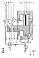
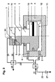
Die Figuren 1 bis 3 zeigen die Vorrichtung im Längsschnitt.
- Fig. 1: Hubsystem und Stelleinheit
- Fig. 2 Hubsystem in der Ausgangsposition ("Geöffneter Behälter")
- Fig.3 Hubsystem ("Geschlossener Behälter")
- Fig. 1: lifting system and actuator
- Fig. 2 lifting system in the starting position ( "open container" )
- Fig.3 Lifting system ( "closed container" )
Anhand von Erläuterungen und einem Beispiel soll die Vorrichtung und das Verfahren näher beschrieben werden. Fig. 1 zeigt das Hubsystem und eine Stelleinheit 20, wobei hier beispielhaft alle Druckleitungen und die Zu- und Ableitung diese Stelleinheit 20 durchlaufen.By way of explanation and an example, the device and the method will be described in more detail. Fig. 1 shows the lifting system and an
Fig. 2 und Fig. 3 zeigen beispielhaft die Stelleinheit als Ventil 20, Ventil 26 und Drossel 27. Weiterhin zeigen sie die Durchführung des offenbarten Verfahrens unter Einbindung der vorgenannten und erfindungsgemäßen Vorrichtung. Diese läuft derart, dass durch die Schaltung des Ventils 20 der Hohlraum unterhalb der Bodenfläche 11 des Arbeitskolbens 1 und der Behälter 8 über die Druckleitungen und die Bohrungen mit Fluid beaufschlagt werden, wobei Ventil 26 die Druckleitung 23 verschließ, und somit
der Arbeitskolben 1 aus der Ausgangsposition "Offener Behälter" (Fig. 2) in die Position "Geschlossener Behälter" (Fig. 3) gefahren wird und den Behälter verschließt, und- nach
Prozessende das Ventil 20 derart geschaltet wird, dass das Fluidim unteren Zylinderhohlraum 12und im Prozessraum 7 entspannt wird, und - anschließend durch weitere Ventilschaltung der obere Zylinderhohlraum 13 im Führungszylinder über die
Druckleitung 24 und dieBohrung 6 mit Fluid beaufschlagt wird, so dass derArbeitskolben 1 wieder in die Ausgangsposition "Geöffneter Behälter" verfährt.
- the working
piston 1 is moved from the starting position "open container" (FIG. 2) into the position "closed container" (FIG. 3) and closes the container, and - After the end of the
process valve 20 is switched so that the fluid in thelower cylinder cavity 12 and in theprocess chamber 7 is relaxed, and - Subsequently, through further valve switching, the
upper cylinder cavity 13 in the guide cylinder is acted upon by fluid via thepressure line 24 and thebore 6, so that the workingpiston 1 again moves into the starting position "opened container".
Anhand eines Beispiels soll nachstehend die erfindungsgemäße Vorrichtung und das Verfahren zu dessen Einsatz näher erläutert werden.By way of example, the device according to the invention and the method for its use will be explained in more detail below.
Wie in Fig. 2 dargestellt, umfasst die Vorrichtung eine Vorrichtung zum Verschließen eines Behälters, welcher im Wesentlichen aus einem statischen Basisteil und einem mobilen Verschlussteil besteht. Zwischen den beiden Teilen ist eine Dichtfläche angeordnet. Im Prozessraum, der sich zwischen den beiden Teilen ausbildet, werden Prozesse mit mindestens einem Prozessfluid durchgeführt. Der Verschluss geschieht mittels eines rotationssymmetrischen Hubsystems, das aus einem bewegten rotationssymmetrischen Arbeitskolben 1 mit einem Führungszylinder 4 besteht.As shown in Fig. 2, the device comprises a device for closing a container, which essentially consists of a static base part and a mobile closure part. Between the two parts a sealing surface is arranged. In the process space, which forms between the two parts, processes are carried out with at least one process fluid. The closure takes place by means of a rotationally symmetrical lifting system, which consists of a moving rotationally
Das im Führungszylinder 4 befindlichen Kolbenende weist eine auf der äußeren Oberfläche radial umlaufende Verstärkung 3 auf, so dass der Innenraum zwischen Führungszylinder und Arbeitskolben in zwei Hohlräume geteilt wird. Je eine Öffnung im Führungszylinder führt zu jedem der beiden Hohlräume, wobei diese Bohrungen über Druckleitungen mit einem Ventil verbunden sind. Über eine Zuleitung 21 wird das Prozess- und Arbeitsfluid zugeführt, so dass für den Kolbenantrieb und den Prozess im Prozessraum 7 im Wesentlichen das selbe Fluid genutzt wird. Dabei kann dem Fluid ein Additiv zugesetzt sein, dass für den Prozess im Prozessraum 7 erforderlich ist.The piston end located in the
Die Stirnseite des Arbeitskolbens stellt das Verschlussteil des Behälters 8 dar und wird entlang der Rotationsachse senkrecht verfahren. Die Bodenfläche 11 des Arbeitskolbens 1 ist größer als die Anpressfläche zwischen Basisteil und Verschlussteil des Behälters.The end face of the working piston is the closure part of the
Die vorstehend beschriebene Vorrichtung umfasst, wie in Fig. 2 und Fig. 3 dargestellt, ein zentrales Ventil 20 sowie die in Ableitung 22 eingebunden Drossel 27 und das in die Zuleitung 23 eingebrachte Ventil 26.
- Zu Beginn eines Hubzyklusses
ist das Ventil 26 geschlossen. Durch - Stellung des Ventils 20 wird über die
Druckleitung 25 und dieBohrung 5 der untere Zylinderhohlraum 12 mit Fluid beaufschlagt, wobei zeitgleich Fluid ausdem oberen Zylinderraum 13 über dieBohrung 6 und dieDruckleitung 24 entweichen kann.Die Leitungen 23 und 24 sind anfänglich durch dieVentile 20 und 26 verschlossen. Durch das Erreichen eines definierten Drucks in derDruckleitung 23 bzw. inder Stirnfläche 10 oder nach einer festgelegten Zeit, wird das Ventil 26 geöffnet und der Prozessraum 7 über dieBohrung 9 und die Druckleitung 29 mit Fluid beaufschlagt. Das beladene Prozessfluid fließt über dieBohrung 30 und dieDruckleitung 31 ab. Nach Ende desProzesses im Prozessraum 7 wird- durch Stellung des Ventils 28 der
Druck im Prozessraum 7 entspannt, indem dasFluid über Bohrung 9 und Druckleitung 28 entweichen kann. Während dieses Entspannungsvorgangs oder anschließend, wird durch - Stellung des Ventils 20 der obere Zylinderraum 13 über die Druckleitung 24 und die
Bohrung 6 mit Fluid beaufschlagt und zeitgleich über dieDruckleitung 25 und dieBohrung 5 der Druckim unteren Zylinderraum 12 entspannt. Dadurch verfährt der Arbeitskolben in die Position "Geöffneter Behälter" und der Prozessraum kann entleert bzw. beladen werden. Nach - Stellung des Ventils 28, welches die Absperrung der Druckleitung 23 bewirkt, ist wieder die Ausgangsposition des Hubzyklusses erreicht.
- At the beginning of a Hubzyklusses the
valve 26 is closed. By - Position of the
valve 20 is applied via thepressure line 25 and thebore 5 of thelower cylinder cavity 12 with fluid, at the same time fluid from theupper cylinder chamber 13 via thebore 6 and thepressure line 24 can escape. Thelines valves pressure line 23 or in theend face 10 or after a specified time, - the
valve 26 is opened and theprocess chamber 7 is acted upon via thebore 9 and the pressure line 29 with fluid. The loaded process fluid flows through thebore 30 and thepressure line 31. After the end of the process in theprocess room 7 becomes - by the position of the
valve 28, the pressure in theprocess chamber 7 relaxes by the fluid throughhole 9 andpressure line 28 can escape. During this relaxation process, or subsequently, will through - Position of the
valve 20, theupper cylinder chamber 13 via thepressure line 24 and thebore 6 is acted upon by fluid and at the same time on thepressure line 25 and thebore 5, the pressure in thelower cylinder chamber 12 relaxed. As a result, the working piston moves into the position "Opened container" and the process room can be emptied or loaded. To - Position of the
valve 28, which causes the blocking of thepressure line 23, the initial position of the Hubzyklusses is reached again.
Wie vorstehend genannt, besteht eine vorteilhafte Funktion der Reinraumvorrichtung darin, dass bei der gleichzeitigen Beaufschlagung des Prozessraumes 7 und des unteren Zylinderhohlraums 12 mit Fluid, der Zulauf in den Behälter 8 über den Leitungsweg 23 gedrosselt oder zeitlich verzögert wird, so dass der Anpressdruck in der Dichtfläche zwischen Basis- und Verschlussteil des Behälters immer größer als der Druck im Behälter ist.As mentioned above, there is an advantageous function of the clean room device is that when simultaneous loading of the
Analog zur vorgenannten Optimierung ist eine vorteilhafte Ausgestaltung darin zu sehen, dass bei der gleichzeitigen Entspannung des Behälters 8 und des unteren Zylinderhohlraums 12 der Fluidabfluss aus dem unteren Zylinderhohlraum 12 gedrosselt oder zeitlich verzögert wird, so dass der Anpressdruck in der Dichtfläche zwischen Basis- und Verschlussteil des Behälters 8 immer größer als der Druck im Prozessraum 7 ist.Analogous to the above optimization, an advantageous embodiment is to be seen in the fact that in the simultaneous relaxation of the
Claims (15)
- High-pressure device for operating closures of vessel (8) and suited for clean-room applications, which consists of a base part and a closure part with a sealing member arranged between said parts, and for implementing the process with at least one process fluid and by means of a rotation-symmetric reciprocating piston system, said system comprising at least one rotation-symmetric hydraulic piston (1) with one guide cylinder (4) each, hydraulic piston (1) being linked to guide cylinder (4) at the piston end that has at least one radial and circumferential reinforcement (3) on its external surface so that the inner space between guide cylinder (4) and hydraulic piston (1) is separated into at least one lower cylinder chamber (12) and an upper cylinder chamber (13) and at least one bore (5 and 6) is provided in the guide cylinder (4) for each of cylinder chambers (12 and 13), said bores (5 and 6) being connected to at least one setting and control unit (20) either direct or via lines (24 and 25), said settable unit controlling the delivery to and the discharge from cylinder chambers (12 and 13) of guide cylinder (4), the upper face of the hydraulic piston either constituting part of the closure or being provided with a rigid connection to said closure of the vessel and that the major part of this closure also moves essentially along the axis of rotation referred to the hydraulic piston, the vessel being arranged on the opposite side of the upper face of the hydraulic piston and that the lower face of the hydraulic piston is larger than the contact surface between the base part and the closure part of the vessel, characterised in that- the fluid for driving hydraulic piston (1) is identical with the main component of the process fluid used in pressure vessel (8) and the process fluid is either a supercritical gas or a highly volatile fluid, and- at least one of sliding surfaces (14, 15 and 16), which are located on the inner wall side of the cylinder and on the respective piston surfaces and where the cylinder and the piston surfaces come into contact as members facing each other and moving parallel to the axis of rotation, has a >60% support ratio, said figure being the ratio of the portion of peaks in relation to the portion of valleys in the surface structure.
- Device according to claim 1,
characterised in that at least one of sliding surfaces (14, 15 and 16), which are located on the inner wall side of the cylinder and on the respective piston surfaces and where the cylinder and the piston surfaces come into contact as members facing each other and move parallel to the axis of rotation, is subjected to a hardening process. - Device according to one of the preceding claims 1 or 2,
characterised in that at least one of the lines connected to the bores is provided with a restrictor directly upstream or downstream of the valve. - Device according to one of the preceding claims 1 to 3,
characterised in that the supercritical fluid is, for example, carbon dioxide (CO2), compressed air, nitrogen or inert gas or a mixture thereof. - Device according to one of the preceding claims 1 to 3,
characterised in that the highly volatile fluid is taken from the group constituted by ethanol, methanol, isopropanol and comparable substances or mixtures thereof, or as option a gas mainly consisting of CO2, oxygen, nitrogen, a noble gas or mixtures thereof. - Device according to one of the preceding claims 1 to 5,
characterised in that an operating pressure of >160 bar is regularly reached at the upper face of the hydraulic piston. - Process for the utilisation of the device according to one of the preceding claims 1 to 6,
characterised in that■ the switching of the valve initiates the filling with fluid of the space underneath the lower face of the hydraulic piston and the vessel via the delivery lines and the bores with the aid of fluid,■ the hydraulic piston thus moves from the starting position "Vessel open" so that the vessel is opened, to the position "Vessel closed" so that the vessel is closed,■ the setting and control unit is switched at the end of the process in the vessel in such a manner that the fluid in the space underneath the lower piston end and in the process chamber is flashed,■ further valve switching ensures that the upper cylinder chamber in the guide cylinder is filled with fluid via the delivery line and the bore so that the hydraulic piston returns to its starting position "Vessel open". - Process according to claim 7,
characterised in that the regular pressure in the vessel is >160 bar. - Process according to claims 7 or 8,
characterised in that the setting and control unit comprises at least one valve. - Process according to one of the preceding claims 7 to 9,
characterised in that the setting and control unit comprises at least one static or dynamic fluid restrictor. - Process according to one of the preceding claims 7 to 10,
characterised in that the feed stream to the vessel and the cylinder chamber is restricted and/or delayed when the vessel and the cylinder chamber are pressurised with fluid simultaneously. - Process according to one of the preceding claims 7 to 11,
characterised in that a simultaneous depressurisation of the vessel and the lower cylinder chamber takes place, the fluid discharge stream from the cylinder chamber underneath the lower face of the hydraulic piston being restricted and/or delayed. - Utilization of the process or device according to one of the preceding claims 1 to 12,
characterised in that the device or process is used in conjunction with the application, production or a process applied in the semi-conductor industries and/or in the wafer production. - Utilization of the process or device according to one of the preceding claims 1 to 12,
characterised in that the device or process is used in conjunction with the application, production or a process applied in the optics industries. - Utilization of the process or device according to one of the preceding claims 1 to 12,
characterised in that the device or process is used in conjunction with the application, production or a process applied in the pharmaceuticals or medical/medicinal products industries.
Priority Applications (1)
| Application Number | Priority Date | Filing Date | Title |
|---|---|---|---|
| SI200330569T SI1565656T1 (en) | 2002-11-26 | 2003-11-13 | High-pressure device for closing a container in a clean room |
Applications Claiming Priority (3)
| Application Number | Priority Date | Filing Date | Title |
|---|---|---|---|
| DE10255231 | 2002-11-26 | ||
| DE10255231A DE10255231B4 (en) | 2002-11-26 | 2002-11-26 | High pressure device for closing a pressure vessel in the clean room |
| PCT/DE2003/003756 WO2004048783A2 (en) | 2002-11-26 | 2003-11-13 | High-pressure device for closing a container |
Publications (2)
| Publication Number | Publication Date |
|---|---|
| EP1565656A2 EP1565656A2 (en) | 2005-08-24 |
| EP1565656B1 true EP1565656B1 (en) | 2006-09-20 |
Family
ID=32308733
Family Applications (1)
| Application Number | Title | Priority Date | Filing Date |
|---|---|---|---|
| EP03795731A Expired - Lifetime EP1565656B1 (en) | 2002-11-26 | 2003-11-13 | High-pressure device for closing a container in a clean room |
Country Status (12)
| Country | Link |
|---|---|
| US (1) | US20070037399A1 (en) |
| EP (1) | EP1565656B1 (en) |
| JP (1) | JP2006508307A (en) |
| KR (1) | KR20050074639A (en) |
| CN (1) | CN100401462C (en) |
| AT (1) | ATE340410T1 (en) |
| AU (1) | AU2003298050A1 (en) |
| DE (2) | DE10255231B4 (en) |
| ES (1) | ES2268478T3 (en) |
| MY (1) | MY136175A (en) |
| TW (1) | TWI295344B (en) |
| WO (1) | WO2004048783A2 (en) |
Families Citing this family (6)
| Publication number | Priority date | Publication date | Assignee | Title |
|---|---|---|---|---|
| DE102004032659B4 (en) * | 2004-07-01 | 2008-10-30 | Atotech Deutschland Gmbh | Apparatus and method for the chemical or electrolytic treatment of material to be treated and the use of the device |
| KR100721757B1 (en) * | 2006-06-08 | 2007-05-25 | 두산디앤디 주식회사 | Cleaning material pressurization device for wafer surface polishing equipment |
| CN101912750B (en) * | 2010-08-18 | 2012-09-05 | 郑州人造金刚石及制品工程技术研究中心有限公司 | Rotary propelling device |
| KR102358561B1 (en) * | 2017-06-08 | 2022-02-04 | 삼성전자주식회사 | Substrate processing apparatus and apparatus for manufacturing integrated circuit device |
| KR102852007B1 (en) | 2020-12-30 | 2025-08-29 | 세메스 주식회사 | Supporting device and apparatus for processing a substrate including a supporting device |
| CN116498755B (en) * | 2023-06-27 | 2023-08-29 | 中北大学 | Supercritical carbon dioxide differential pressure control type quick switch valve |
Family Cites Families (51)
| Publication number | Priority date | Publication date | Assignee | Title |
|---|---|---|---|---|
| JPS5838010U (en) * | 1981-09-07 | 1983-03-12 | エスエムシ−株式会社 | booster cylinder |
| JPS58157005U (en) * | 1982-04-15 | 1983-10-20 | 株式会社小松製作所 | Double acting cylinder device |
| JPS61119874A (en) * | 1984-11-14 | 1986-06-07 | Hitachi Constr Mach Co Ltd | Cylinder device |
| JPS6317455U (en) * | 1986-07-16 | 1988-02-05 | ||
| US4962776A (en) * | 1987-03-26 | 1990-10-16 | Regents Of The University Of Minnesota | Process for surface and fluid cleaning |
| JPS6445131A (en) * | 1987-08-14 | 1989-02-17 | Hitachi Ltd | Cleaning and oxidation of semiconductor wafer |
| JPH0662639B2 (en) * | 1987-12-04 | 1994-08-17 | 武田薬品工業株式会社 | Cefem hydrochloride crystals |
| JPH01170026A (en) * | 1987-12-25 | 1989-07-05 | Chlorine Eng Corp Ltd | Cleaning of semiconductor substrate |
| JPH01204427A (en) * | 1988-02-10 | 1989-08-17 | Hitachi Ltd | Semiconductor device |
| JPH0780846B2 (en) * | 1988-04-02 | 1995-08-30 | 三井東圧化学株式会社 | Method for producing high-purity indole |
| JPH01294516A (en) * | 1988-05-20 | 1989-11-28 | Koroido Res:Kk | Production of cellular silica based gel |
| JPH0225447A (en) * | 1988-07-13 | 1990-01-26 | Nippon Oil & Fats Co Ltd | Production of highly unsaturated fatty acids |
| EP0350909B1 (en) * | 1988-07-14 | 1993-10-20 | Union Carbide Corporation | Electrostatic liquid spray application of coatings with supercritical fluids as diluents and spraying from an orifice |
| JPH0298928A (en) * | 1988-10-05 | 1990-04-11 | Toshiba Corp | Cleaning of semiconductor substrate |
| US5013366A (en) * | 1988-12-07 | 1991-05-07 | Hughes Aircraft Company | Cleaning process using phase shifting of dense phase gases |
| JPH02238887A (en) * | 1989-03-10 | 1990-09-21 | Mitsui Toatsu Chem Inc | Purification of material produced by enzyme |
| JPH02292216A (en) * | 1989-05-02 | 1990-12-03 | Mori Seiyu Kk | Removal of solvent of drugs by extraction with supercritical carbon dioxide gas |
| NL8901578A (en) * | 1989-06-22 | 1991-01-16 | Suiker Unie | PROCESS FOR PURIFYING PRODUCTS WITH ESTERS OF A NON-REDUCING SUGAR AND ONE OR MORE FATTY ACIDS. |
| JPH0351576A (en) * | 1989-07-20 | 1991-03-05 | Mitsubishi Heavy Ind Ltd | Abrasion-resistive hydraulic device |
| JPH03174330A (en) * | 1989-09-08 | 1991-07-29 | Seiko Epson Corp | Glass manufacturing method |
| JPH03127832A (en) * | 1989-10-13 | 1991-05-30 | Matsushita Electric Ind Co Ltd | Manufacture of semiconductor device and drying equipment |
| JPH03135402A (en) * | 1989-10-20 | 1991-06-10 | Hitachi Ltd | Extractor for supercritical gas or liquefied gas |
| JPH0367704U (en) * | 1989-10-25 | 1991-07-02 | ||
| GB8928250D0 (en) * | 1989-12-14 | 1990-02-21 | Erba Carlo Spa | Use of supercritical fluids to obtain porous sponges of biodegradable polymers |
| US5169408A (en) * | 1990-01-26 | 1992-12-08 | Fsi International, Inc. | Apparatus for wafer processing with in situ rinse |
| JPH03261128A (en) * | 1990-03-09 | 1991-11-21 | Sumitomo Seika Chem Co Ltd | Method of removing organic hardening film |
| JPH03285658A (en) * | 1990-03-30 | 1991-12-16 | Shirako:Kk | Odorless laver and production of physiologically active substance |
| JPH0417333A (en) * | 1990-05-10 | 1992-01-22 | Hitachi Ltd | Substrate cleaning method and cleaning system using supercritical gas |
| HUT63158A (en) * | 1990-05-23 | 1993-07-28 | Lipogenics Inc | Process for obtaining tokotrienols, tokoferols and tokotrienol-like compounds and pahrmaceutical compositions comprising same as active ingredient |
| US5259407A (en) * | 1990-06-15 | 1993-11-09 | Matrix Inc. | Surface treatment method and apparatus for a semiconductor wafer |
| US5139681A (en) * | 1990-10-09 | 1992-08-18 | The Dow Chemical Company | On-line multidimensional chromatographic system with large volume injection handling for supercritical fluid chromatography |
| JPH0613361A (en) * | 1992-06-26 | 1994-01-21 | Tokyo Electron Ltd | Processor |
| JPH08181050A (en) * | 1995-08-21 | 1996-07-12 | Masaru Nishikawa | Resist removal method and substrate cleaning method |
| US5857368A (en) * | 1995-10-06 | 1999-01-12 | Applied Materials, Inc. | Apparatus and method for fabricating metal paths in semiconductor substrates through high pressure extrusion |
| CN2257511Y (en) * | 1996-06-19 | 1997-07-09 | 陈立群 | Multifunction oil pressure wheel disassembling apparatus |
| DE19746241C2 (en) * | 1997-10-20 | 2000-05-31 | Vat Holding Ag Haag | Device for closing an opening |
| US6067728A (en) * | 1998-02-13 | 2000-05-30 | G.T. Equipment Technologies, Inc. | Supercritical phase wafer drying/cleaning system |
| US6508259B1 (en) * | 1999-08-05 | 2003-01-21 | S.C. Fluids, Inc. | Inverted pressure vessel with horizontal through loading |
| US6497239B2 (en) * | 1999-08-05 | 2002-12-24 | S. C. Fluids, Inc. | Inverted pressure vessel with shielded closure mechanism |
| US6612317B2 (en) * | 2000-04-18 | 2003-09-02 | S.C. Fluids, Inc | Supercritical fluid delivery and recovery system for semiconductor wafer processing |
| US6602349B2 (en) * | 1999-08-05 | 2003-08-05 | S.C. Fluids, Inc. | Supercritical fluid cleaning process for precision surfaces |
| US6334266B1 (en) * | 1999-09-20 | 2002-01-01 | S.C. Fluids, Inc. | Supercritical fluid drying system and method of use |
| US20040025908A1 (en) * | 2000-04-18 | 2004-02-12 | Stephen Douglas | Supercritical fluid delivery system for semiconductor wafer processing |
| US20040003831A1 (en) * | 2000-04-18 | 2004-01-08 | Mount David J. | Supercritical fluid cleaning process for precision surfaces |
| EP1303870A2 (en) * | 2000-07-26 | 2003-04-23 | Tokyo Electron Limited | High pressure processing chamber for semiconductor substrate |
| US20020189543A1 (en) * | 2001-04-10 | 2002-12-19 | Biberger Maximilian A. | High pressure processing chamber for semiconductor substrate including flow enhancing features |
| US20030116176A1 (en) * | 2001-04-18 | 2003-06-26 | Rothman Laura B. | Supercritical fluid processes with megasonics |
| JP2002327712A (en) * | 2001-05-02 | 2002-11-15 | Sumitomo Precision Prod Co Ltd | Aircraft leg lifting device |
| DE10255230A1 (en) * | 2002-11-26 | 2004-06-09 | Uhde High Pressure Technologies Gmbh | High-pressure device and method for hydraulic-pneumatic power stroke for clean room applications |
| US7225820B2 (en) * | 2003-02-10 | 2007-06-05 | Tokyo Electron Limited | High-pressure processing chamber for a semiconductor wafer |
| US7077917B2 (en) * | 2003-02-10 | 2006-07-18 | Tokyo Electric Limited | High-pressure processing chamber for a semiconductor wafer |
-
2002
- 2002-11-26 DE DE10255231A patent/DE10255231B4/en not_active Expired - Fee Related
-
2003
- 2003-11-03 MY MYPI20034193A patent/MY136175A/en unknown
- 2003-11-13 KR KR1020057009298A patent/KR20050074639A/en not_active Withdrawn
- 2003-11-13 AU AU2003298050A patent/AU2003298050A1/en not_active Abandoned
- 2003-11-13 CN CNB2003801041564A patent/CN100401462C/en not_active Expired - Fee Related
- 2003-11-13 US US10/536,379 patent/US20070037399A1/en not_active Abandoned
- 2003-11-13 DE DE50305138T patent/DE50305138D1/en not_active Expired - Fee Related
- 2003-11-13 EP EP03795731A patent/EP1565656B1/en not_active Expired - Lifetime
- 2003-11-13 WO PCT/DE2003/003756 patent/WO2004048783A2/en not_active Ceased
- 2003-11-13 JP JP2004554203A patent/JP2006508307A/en active Pending
- 2003-11-13 AT AT03795731T patent/ATE340410T1/en not_active IP Right Cessation
- 2003-11-13 ES ES03795731T patent/ES2268478T3/en not_active Expired - Lifetime
- 2003-11-25 TW TW092132981A patent/TWI295344B/en active
Also Published As
| Publication number | Publication date |
|---|---|
| CN1717775A (en) | 2006-01-04 |
| EP1565656A2 (en) | 2005-08-24 |
| JP2006508307A (en) | 2006-03-09 |
| ATE340410T1 (en) | 2006-10-15 |
| US20070037399A1 (en) | 2007-02-15 |
| TW200419078A (en) | 2004-10-01 |
| DE10255231B4 (en) | 2006-02-02 |
| KR20050074639A (en) | 2005-07-18 |
| MY136175A (en) | 2008-08-29 |
| AU2003298050A1 (en) | 2004-06-18 |
| WO2004048783A8 (en) | 2005-09-29 |
| DE10255231A1 (en) | 2004-06-09 |
| DE50305138D1 (en) | 2006-11-02 |
| HK1086384A1 (en) | 2006-09-15 |
| TWI295344B (en) | 2008-04-01 |
| AU2003298050A8 (en) | 2004-06-18 |
| WO2004048783A2 (en) | 2004-06-10 |
| ES2268478T3 (en) | 2007-03-16 |
| CN100401462C (en) | 2008-07-09 |
| WO2004048783A3 (en) | 2004-08-05 |
Similar Documents
| Publication | Publication Date | Title |
|---|---|---|
| EP3781815B1 (en) | Compressor device and compression method | |
| DE60023793T2 (en) | Integrated turbopump and control valve system | |
| DE69312738T2 (en) | ROTATING SCREW COMPRESSOR WITH SHAFT SEAL | |
| DE60201409T2 (en) | DISPENSING VALVE WITH DELAYED REMOVAL OF THE COUNTERPLATE | |
| DE69511438T2 (en) | HORIZONTAL PISTON COMPRESSOR | |
| CH678881A5 (en) | ||
| DE102017102841A1 (en) | Multi-way valve for controlling a refrigerant circuit | |
| DE3142230C2 (en) | Device for adjusting the performance of a multi-cylinder refrigerant compressor | |
| DE60314014T2 (en) | SEAL RING FOR A PENDULUM VALVE ASSEMBLY | |
| EP2985497B1 (en) | Closuring element for a vacuum valve with pressed, vulcanised seal | |
| DE102005031411A1 (en) | Method for controlling a vacuum valve arranged between two vacuum chambers | |
| DE3819566A1 (en) | Gap seal | |
| DE10255231B4 (en) | High pressure device for closing a pressure vessel in the clean room | |
| DE19613845A1 (en) | Drive circuit for fluid-operated actuator | |
| DE60004482T2 (en) | INJECTION VALVE FOR GAS | |
| EP1565657B1 (en) | High pressure device for clean room applications | |
| EP2531753B1 (en) | Motor actuated rotary valve | |
| DE69318674T2 (en) | Vacuum pump with an oil-controlled inlet shut-off valve | |
| EP1631746A1 (en) | Hydraulic drive for displacing an actuator | |
| DE102008058306A1 (en) | Aerostatic table system for vacuum application | |
| DE69502036T2 (en) | Driving device for a piston by fluid pressure | |
| DE60218720T2 (en) | COMPOSITION OF SCREW COMPRESSOR AND METHOD | |
| DE102018010348B4 (en) | Compressor device and compression method | |
| DE102019130210B4 (en) | Piston compressor with energy saving device | |
| DE3208908C1 (en) | Ball valve for pipelines having large nominal widths |
Legal Events
| Date | Code | Title | Description |
|---|---|---|---|
| PUAI | Public reference made under article 153(3) epc to a published international application that has entered the european phase |
Free format text: ORIGINAL CODE: 0009012 |
|
| 17P | Request for examination filed |
Effective date: 20050511 |
|
| AK | Designated contracting states |
Kind code of ref document: A2 Designated state(s): AT BE BG CH CY CZ DE DK EE ES FI FR GB GR HU IE IT LI LU MC NL PT RO SE SI SK TR |
|
| AX | Request for extension of the european patent |
Extension state: AL LT LV MK |
|
| RIC1 | Information provided on ipc code assigned before grant |
Ipc: 7H 01L 21/00 A |
|
| GRAP | Despatch of communication of intention to grant a patent |
Free format text: ORIGINAL CODE: EPIDOSNIGR1 |
|
| DAX | Request for extension of the european patent (deleted) | ||
| GRAS | Grant fee paid |
Free format text: ORIGINAL CODE: EPIDOSNIGR3 |
|
| GRAA | (expected) grant |
Free format text: ORIGINAL CODE: 0009210 |
|
| AK | Designated contracting states |
Kind code of ref document: B1 Designated state(s): AT BE BG CH CY CZ DE DK EE ES FI FR GB GR HU IE IT LI LU MC NL PT RO SE SI SK TR |
|
| PG25 | Lapsed in a contracting state [announced via postgrant information from national office to epo] |
Ref country code: IT Free format text: LAPSE BECAUSE OF FAILURE TO SUBMIT A TRANSLATION OF THE DESCRIPTION OR TO PAY THE FEE WITHIN THE PRESCRIBED TIME-LIMIT;WARNING: LAPSES OF ITALIAN PATENTS WITH EFFECTIVE DATE BEFORE 2007 MAY HAVE OCCURRED AT ANY TIME BEFORE 2007. THE CORRECT EFFECTIVE DATE MAY BE DIFFERENT FROM THE ONE RECORDED. Effective date: 20060920 Ref country code: RO Free format text: LAPSE BECAUSE OF FAILURE TO SUBMIT A TRANSLATION OF THE DESCRIPTION OR TO PAY THE FEE WITHIN THE PRESCRIBED TIME-LIMIT Effective date: 20060920 Ref country code: CZ Free format text: LAPSE BECAUSE OF FAILURE TO SUBMIT A TRANSLATION OF THE DESCRIPTION OR TO PAY THE FEE WITHIN THE PRESCRIBED TIME-LIMIT Effective date: 20060920 |
|
| REG | Reference to a national code |
Ref country code: GB Ref legal event code: FG4D Free format text: NOT ENGLISH |
|
| REG | Reference to a national code |
Ref country code: CH Ref legal event code: EP |
|
| REG | Reference to a national code |
Ref country code: CH Ref legal event code: NV Representative=s name: PATENTANWAELTE SCHAAD, BALASS, MENZL & PARTNER AG |
|
| REG | Reference to a national code |
Ref country code: IE Ref legal event code: FG4D Free format text: LANGUAGE OF EP DOCUMENT: GERMAN |
|
| REF | Corresponds to: |
Ref document number: 50305138 Country of ref document: DE Date of ref document: 20061102 Kind code of ref document: P |
|
| PGFP | Annual fee paid to national office [announced via postgrant information from national office to epo] |
Ref country code: HU Payment date: 20061127 Year of fee payment: 4 |
|
| PG25 | Lapsed in a contracting state [announced via postgrant information from national office to epo] |
Ref country code: MC Free format text: LAPSE BECAUSE OF NON-PAYMENT OF DUE FEES Effective date: 20061130 Ref country code: BE Free format text: LAPSE BECAUSE OF NON-PAYMENT OF DUE FEES Effective date: 20061130 |
|
| PG25 | Lapsed in a contracting state [announced via postgrant information from national office to epo] |
Ref country code: DK Free format text: LAPSE BECAUSE OF FAILURE TO SUBMIT A TRANSLATION OF THE DESCRIPTION OR TO PAY THE FEE WITHIN THE PRESCRIBED TIME-LIMIT Effective date: 20061220 Ref country code: SE Free format text: LAPSE BECAUSE OF FAILURE TO SUBMIT A TRANSLATION OF THE DESCRIPTION OR TO PAY THE FEE WITHIN THE PRESCRIBED TIME-LIMIT Effective date: 20061220 |
|
| REG | Reference to a national code |
Ref country code: HU Ref legal event code: AG4A Ref document number: E000819 Country of ref document: HU |
|
| GBT | Gb: translation of ep patent filed (gb section 77(6)(a)/1977) |
Effective date: 20061220 |
|
| PG25 | Lapsed in a contracting state [announced via postgrant information from national office to epo] |
Ref country code: PT Free format text: LAPSE BECAUSE OF FAILURE TO SUBMIT A TRANSLATION OF THE DESCRIPTION OR TO PAY THE FEE WITHIN THE PRESCRIBED TIME-LIMIT Effective date: 20070312 |
|
| REG | Reference to a national code |
Ref country code: ES Ref legal event code: FG2A Ref document number: 2268478 Country of ref document: ES Kind code of ref document: T3 |
|
| ET | Fr: translation filed | ||
| PLBE | No opposition filed within time limit |
Free format text: ORIGINAL CODE: 0009261 |
|
| STAA | Information on the status of an ep patent application or granted ep patent |
Free format text: STATUS: NO OPPOSITION FILED WITHIN TIME LIMIT |
|
| 26N | No opposition filed |
Effective date: 20070621 |
|
| BERE | Be: lapsed |
Owner name: UHDE HIGH PRESSURE TECHNOLOGIES G.M.B.H. Effective date: 20061130 |
|
| PGFP | Annual fee paid to national office [announced via postgrant information from national office to epo] |
Ref country code: DE Payment date: 20071123 Year of fee payment: 5 Ref country code: ES Payment date: 20071129 Year of fee payment: 5 Ref country code: NL Payment date: 20071119 Year of fee payment: 5 |
|
| PGFP | Annual fee paid to national office [announced via postgrant information from national office to epo] |
Ref country code: IT Payment date: 20071122 Year of fee payment: 5 Ref country code: FI Payment date: 20071115 Year of fee payment: 5 Ref country code: CH Payment date: 20071115 Year of fee payment: 5 Ref country code: BG Payment date: 20071116 Year of fee payment: 5 |
|
| PG25 | Lapsed in a contracting state [announced via postgrant information from national office to epo] |
Ref country code: GR Free format text: LAPSE BECAUSE OF FAILURE TO SUBMIT A TRANSLATION OF THE DESCRIPTION OR TO PAY THE FEE WITHIN THE PRESCRIBED TIME-LIMIT Effective date: 20061221 |
|
| PGFP | Annual fee paid to national office [announced via postgrant information from national office to epo] |
Ref country code: FR Payment date: 20071122 Year of fee payment: 5 Ref country code: GB Payment date: 20071120 Year of fee payment: 5 |
|
| PG25 | Lapsed in a contracting state [announced via postgrant information from national office to epo] |
Ref country code: SK Free format text: LAPSE BECAUSE OF NON-PAYMENT OF DUE FEES Effective date: 20061113 Ref country code: EE Free format text: LAPSE BECAUSE OF FAILURE TO SUBMIT A TRANSLATION OF THE DESCRIPTION OR TO PAY THE FEE WITHIN THE PRESCRIBED TIME-LIMIT Effective date: 20060920 |
|
| PG25 | Lapsed in a contracting state [announced via postgrant information from national office to epo] |
Ref country code: LU Free format text: LAPSE BECAUSE OF NON-PAYMENT OF DUE FEES Effective date: 20061113 Ref country code: TR Free format text: LAPSE BECAUSE OF FAILURE TO SUBMIT A TRANSLATION OF THE DESCRIPTION OR TO PAY THE FEE WITHIN THE PRESCRIBED TIME-LIMIT Effective date: 20060920 Ref country code: HU Free format text: LAPSE BECAUSE OF NON-PAYMENT OF DUE FEES Effective date: 20071114 |
|
| PG25 | Lapsed in a contracting state [announced via postgrant information from national office to epo] |
Ref country code: CY Free format text: LAPSE BECAUSE OF FAILURE TO SUBMIT A TRANSLATION OF THE DESCRIPTION OR TO PAY THE FEE WITHIN THE PRESCRIBED TIME-LIMIT Effective date: 20060920 |
|
| PGFP | Annual fee paid to national office [announced via postgrant information from national office to epo] |
Ref country code: AT Payment date: 20081114 Year of fee payment: 6 |
|
| PGFP | Annual fee paid to national office [announced via postgrant information from national office to epo] |
Ref country code: SI Payment date: 20081103 Year of fee payment: 6 |
|
| REG | Reference to a national code |
Ref country code: CH Ref legal event code: PL |
|
| GBPC | Gb: european patent ceased through non-payment of renewal fee |
Effective date: 20081113 |
|
| PG25 | Lapsed in a contracting state [announced via postgrant information from national office to epo] |
Ref country code: FI Free format text: LAPSE BECAUSE OF NON-PAYMENT OF DUE FEES Effective date: 20081113 Ref country code: NL Free format text: LAPSE BECAUSE OF NON-PAYMENT OF DUE FEES Effective date: 20090601 |
|
| NLV4 | Nl: lapsed or anulled due to non-payment of the annual fee |
Effective date: 20090601 |
|
| PG25 | Lapsed in a contracting state [announced via postgrant information from national office to epo] |
Ref country code: IT Free format text: LAPSE BECAUSE OF NON-PAYMENT OF DUE FEES Effective date: 20081113 |
|
| PGFP | Annual fee paid to national office [announced via postgrant information from national office to epo] |
Ref country code: IE Payment date: 20071122 Year of fee payment: 5 |
|
| REG | Reference to a national code |
Ref country code: FR Ref legal event code: ST Effective date: 20090731 |
|
| PG25 | Lapsed in a contracting state [announced via postgrant information from national office to epo] |
Ref country code: CH Free format text: LAPSE BECAUSE OF NON-PAYMENT OF DUE FEES Effective date: 20081130 Ref country code: LI Free format text: LAPSE BECAUSE OF NON-PAYMENT OF DUE FEES Effective date: 20081130 Ref country code: IE Free format text: LAPSE BECAUSE OF NON-PAYMENT OF DUE FEES Effective date: 20081113 Ref country code: DE Free format text: LAPSE BECAUSE OF NON-PAYMENT OF DUE FEES Effective date: 20090603 |
|
| PG25 | Lapsed in a contracting state [announced via postgrant information from national office to epo] |
Ref country code: GB Free format text: LAPSE BECAUSE OF NON-PAYMENT OF DUE FEES Effective date: 20081113 |
|
| REG | Reference to a national code |
Ref country code: ES Ref legal event code: FD2A Effective date: 20081114 |
|
| PG25 | Lapsed in a contracting state [announced via postgrant information from national office to epo] |
Ref country code: ES Free format text: LAPSE BECAUSE OF NON-PAYMENT OF DUE FEES Effective date: 20081114 |
|
| PG25 | Lapsed in a contracting state [announced via postgrant information from national office to epo] |
Ref country code: AT Free format text: LAPSE BECAUSE OF NON-PAYMENT OF DUE FEES Effective date: 20091113 |
|
| REG | Reference to a national code |
Ref country code: SI Ref legal event code: KO00 Effective date: 20100721 |
|
| PG25 | Lapsed in a contracting state [announced via postgrant information from national office to epo] |
Ref country code: SI Free format text: LAPSE BECAUSE OF NON-PAYMENT OF DUE FEES Effective date: 20091114 Ref country code: BG Free format text: LAPSE BECAUSE OF NON-PAYMENT OF DUE FEES Effective date: 20081130 |
|
| PG25 | Lapsed in a contracting state [announced via postgrant information from national office to epo] |
Ref country code: FR Free format text: LAPSE BECAUSE OF NON-PAYMENT OF DUE FEES Effective date: 20081130 |