EP1565360B1 - Wischarm einer wischvorrichtung - Google Patents
Wischarm einer wischvorrichtung Download PDFInfo
- Publication number
- EP1565360B1 EP1565360B1 EP03767592A EP03767592A EP1565360B1 EP 1565360 B1 EP1565360 B1 EP 1565360B1 EP 03767592 A EP03767592 A EP 03767592A EP 03767592 A EP03767592 A EP 03767592A EP 1565360 B1 EP1565360 B1 EP 1565360B1
- Authority
- EP
- European Patent Office
- Prior art keywords
- wiper
- wiper arm
- section
- hinge pin
- arm
- Prior art date
- Legal status (The legal status is an assumption and is not a legal conclusion. Google has not performed a legal analysis and makes no representation as to the accuracy of the status listed.)
- Expired - Lifetime
Links
- 230000008878 coupling Effects 0.000 claims abstract description 27
- 238000010168 coupling process Methods 0.000 claims abstract description 27
- 238000005859 coupling reaction Methods 0.000 claims abstract description 27
- 238000004519 manufacturing process Methods 0.000 description 8
- 230000008901 benefit Effects 0.000 description 5
- 238000005516 engineering process Methods 0.000 description 3
- 206010047571 Visual impairment Diseases 0.000 description 1
- 238000010276 construction Methods 0.000 description 1
- 208000029257 vision disease Diseases 0.000 description 1
- 230000000007 visual effect Effects 0.000 description 1
- 230000004393 visual impairment Effects 0.000 description 1
Images
Classifications
-
- B—PERFORMING OPERATIONS; TRANSPORTING
- B60—VEHICLES IN GENERAL
- B60S—SERVICING, CLEANING, REPAIRING, SUPPORTING, LIFTING, OR MANOEUVRING OF VEHICLES, NOT OTHERWISE PROVIDED FOR
- B60S1/00—Cleaning of vehicles
- B60S1/02—Cleaning windscreens, windows or optical devices
- B60S1/04—Wipers or the like, e.g. scrapers
- B60S1/32—Wipers or the like, e.g. scrapers characterised by constructional features of wiper blade arms or blades
- B60S1/40—Connections between blades and arms
- B60S1/4067—Connections between blades and arms for arms provided with a side pin
- B60S1/407—Connections between blades and arms for arms provided with a side pin with means provided on the arm for locking the side pin
-
- B—PERFORMING OPERATIONS; TRANSPORTING
- B60—VEHICLES IN GENERAL
- B60S—SERVICING, CLEANING, REPAIRING, SUPPORTING, LIFTING, OR MANOEUVRING OF VEHICLES, NOT OTHERWISE PROVIDED FOR
- B60S1/00—Cleaning of vehicles
- B60S1/02—Cleaning windscreens, windows or optical devices
- B60S1/04—Wipers or the like, e.g. scrapers
- B60S1/32—Wipers or the like, e.g. scrapers characterised by constructional features of wiper blade arms or blades
- B60S1/38—Wiper blades
- B60S1/3848—Flat-type wiper blade, i.e. without harness
- B60S1/3849—Connectors therefor; Connection to wiper arm; Attached to blade
-
- B—PERFORMING OPERATIONS; TRANSPORTING
- B60—VEHICLES IN GENERAL
- B60S—SERVICING, CLEANING, REPAIRING, SUPPORTING, LIFTING, OR MANOEUVRING OF VEHICLES, NOT OTHERWISE PROVIDED FOR
- B60S1/00—Cleaning of vehicles
- B60S1/02—Cleaning windscreens, windows or optical devices
- B60S1/04—Wipers or the like, e.g. scrapers
- B60S1/32—Wipers or the like, e.g. scrapers characterised by constructional features of wiper blade arms or blades
- B60S1/38—Wiper blades
- B60S1/3806—Means, or measures taken, for influencing the aerodynamic quality of the wiper blades
- B60S1/3808—Spoiler integral with the squeegee
Definitions
- the invention relates to a wiper arm of a wiper device with a coupling portion for connecting a flat wiper blade, wherein the wiper arm at least partially in cross-section U-like, with a back and two side walls is formed.
- Such a wiper arm is from the WO 00/73113 A1 known.
- the coupling portion of such a wiper arm is very complicated to manufacture.
- the wiper arm and the coupling portion in the region in which a transverse to the longitudinal axis of the wiper arm hinge pin is provided in cross-section U-shaped As a result, the realization of the coupling section is very expensive to manufacture.
- the coupling section of the wiper arm serves for connection to a flat wiper blade, which comprises a wiper strip facing the pane to be wiped, at least one strip-like elongated support element and a connection section for connection to the coupling section.
- a flat wiper blade which comprises a wiper strip facing the pane to be wiped, at least one strip-like elongated support element and a connection section for connection to the coupling section.
- the present invention has for its object to provide a wiper arm with a coupling portion on the flat wiper blades, as in particular in the WO 00/73113 A1 are described, are attachable.
- the coupling section of the Wischarms should be produced in this case production technology in a simple manner.
- the coupling portion comprises a freestanding wall portion of the other side wall projecting in the longitudinal direction of the back and a side wall and a hinge pin attached to this wall portion for coupling with a connecting portion of the wiper blade. It is advantageous if the freestanding wall section in a straight line extension to the side wall, of which he is part runs. The wall section is then consequently in the plane of the associated side wall.
- An advantageous embodiment of the invention results when the back is wider in the transverse direction than the hinge pin is long in the transverse direction.
- the central longitudinal axis of the wiper arm lies substantially above the central longitudinal axis of the wiper blade. Consequently, a wiper device can be realized, which is very narrow in plan view of the window to be wiped and represents only a slight visual impairment for the vehicle driver.
- the back at least largely covers a wiper blade arranged on the wiper arm. This protects the part of the wiper blade that lies under the back of the wiper arm.
- a very flat construction wiper device is obtained when the wiper blade is at least partially disposed between the side walls of the wiper arm. In addition, the wiper blade is protected by this.
- the back is formed narrower in the transverse direction than the hinge pin is long in the transverse direction.
- the coupling section comprises a shoulder which adjoins the back and has an L-shaped projection which has a web extending transversely to the longitudinal direction and a stop formed parallel to the wall section.
- the wiper blade is arranged in the assembled state laterally next to the wiper arm.
- Such a wiper blade has the advantage that it builds flat.
- the wiper arm is advantageously designed so that the hinge pin is riveted to the wall portion, which is manufacturing technology easy to implement.
- a wiper device having a wiper arm according to the invention and a comprises flat wiper blade which can be connected to the coupling section of the wiper arm.
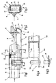
- FIG. 1 shows a wiper arm 10 according to the invention, which comprises a coupling section 12 for connection to a flat wiper blade 14 shown in sections.
- the flat wiper blade 14 has a wiper strip 16, which faces the disk and is shown in FIGS. 2 and 3, has two strap-like elongated support elements 18 and a connection unit 20 connected to the support elements 18.
- a spoiler-like projection 21 is provided on the side facing away from the wiper strip 16.
- the wiper arm 10 is U-shaped in cross-section and has a back 22 and two side walls 24 and 26.
- the back 22 is not perpendicular to the side walls 24 and 26, but is slightly inclined in the direction 27 of the side from which the wind against the wiper arm 10 flows.
- the coupling section 12 comprises a freestanding wall section 28 protruding in the longitudinal direction of the spine 22 and the side wall 24 and a hinge pin 30 extending transversely on the wall section 28.
- the hinge pin 30 engages in a receptacle 32 in the form of a blind hole provided on the connection unit 20 one.
- the wiper blade 14 is disposed at least partially pendulum about the hinge pin 30.
- the hinge pin 30 is, as is clear from Figure 5, riveted to the wall portion 28.
- the wall section 28 provides a hole, or a bore 34, in front.
- wall portion 28 extends in extension of the side wall 26 no separate manufacturing steps for the provision of the wall portion 28 are required. As is apparent from FIG. 1, the wall section 28 lies in the plane of the side wall 26.
- the coupling section 12 provides a lug 36 adjoining the back 22 and having an L-shaped cross-section according to FIG.
- the L-shaped projection 36 in this case has a transverse to the longitudinal direction extending web 38 and a parallel to the wall portion 28 formed stop 40.
- the stop 40 interacts with a counter stop 42, which is inserted laterally on the connection unit 20.
- transverse forces acting on the wiper blade 14 are discharged into the wiper arm 10.
- connection unit 20 On the side facing away from the stop 42, the connection unit 20 is at least in sections, preferably largely free of play, on the wall portion facing her 28th As is clear from Figure 1, the back 22 is formed narrower in the transverse direction, as the hinge pin 30 is long in the transverse direction. It can thereby be achieved that the wiper blade 14 is arranged laterally next to the wiper arm 10 in the mounted state, as a result of which an overall very flat wiper device can be realized.
- FIG. 4 shows a second embodiment of a wiper arm 100 according to the invention.
- the wiper arm 100 has a wall section 128 corresponding to the wall section 28 of the wiper arm 10, on which a hinge pin 130 according to FIG. 5 is arranged by means of a riveted connection.
- the wall portion 128 projects beyond the two side walls 126 and 124 of the cross-sectionally U-shaped wiper arm.
- the back 122 of the wiper arm 100 is made wider than the hinge pin 130 is long in the transverse direction. In this way it can be achieved that a wiper blade to be arranged on the hinge pin 130 is partially covered by the wiper arm 100.
- the wiper blade is then located between the two side walls 124 and 126.
- a wiper arm 100 with a coupling portion 112 shown has the advantage that it can be produced with minimal manufacturing effort. For this purpose, a very narrow wiper device is realized, which obstructs the driver only insignificantly.
Landscapes
- Engineering & Computer Science (AREA)
- Mechanical Engineering (AREA)
- Pivots And Pivotal Connections (AREA)
- Cleaning Implements For Floors, Carpets, Furniture, Walls, And The Like (AREA)
- Baking, Grill, Roasting (AREA)
- Coating Apparatus (AREA)
- Coating With Molten Metal (AREA)
- Power Steering Mechanism (AREA)
- Seal Device For Vehicle (AREA)
Description
- Die Erfindung betrifft einen Wischarm einer Wischvorrichtung mit einem Kopplungsabschnitt zur Anbindung eines Flachwischblatts, wobei der Wischarm wenigstens abschnittsweise im Querschnitt U-artig, mit einem Rücken und zwei Seitenwänden, ausgebildet ist.
- Ein derartiger Wischarm ist aus der
WO 00/73113 A1 - Der Kopplungsabschnitt des Wischarms dient zur Anbindung an ein Flachwischblatt, das eine der zu wischenden Scheibe zugewandte Wischleiste, wenigstens ein bandartig langgestrecktes Tragelement und einen Verbindungsabschnitt zur Anbindung an den Kopplungsabschnitt umfasst. Derartige Flachwischblätter, die keinen kaskadenartigen Bügelaufbau aufweisen, finden zunehmend Verbreitung. Sie bauen regelmäßig sehr flach und sehr schmal, was erhebliche Vorteile mit sich bringt.
- Der vorliegenden Erfindung liegt die Aufgabe zugrunde, einen Wischarm mit einem Kopplungsabschnitt bereitzustellen, an den Flachwischblätter, wie sie insbesondere in der
WO 00/73113 A1 - Diese Aufgabe wird mit einem Wischarm der eingangs beschriebenen Art erfindungsgemäß dadurch gelöst, dass der Kopplungsabschnitt einen in Längsrichtung den Rücken und eine Seitenwand überragenden, freistehenden Wandabschnitt der anderen Seitenwand und einen an diesem Wandabschnitt befestigten Gelenkbolzen zur Kopplung mit einem Verbindungsabschnitt des Wischblatts umfasst. Dabei ist vorteilhaft, wenn der freistehende Wandabschnitt in geradliniger Verlängerung zu der Seitenwand, dessen Teil er ist, verläuft. Der Wandabschnitt liegt dann folglich in der Ebene der zugehörigen Seitenwand.
- Dies hat den Vorteil, dass im Vergleich zum nächstliegenden Stand der Technik der Bereich des Kopplungsabschnitts, an dem der Gelenkbolzen angeordnet ist, lediglich einwandig freistehend ausgebildet ist. Hierdurch wird die Fertigung erheblich vereinfacht. Außerdem ist vorteilhaft, dass der Wischarm, beziehungsweise der Kopplungsabschnitt, schlanker baut, als der Kopplungsabschnitt des nächstliegenden Standes der Technik. Hierdurch kann eine Sichtbehinderung des Fahrzeuglenkers durch die Breite des Wischarms im Bereich des Kopplungsabschnitts minimiert werden.
- Eine vorteilhafte Ausführungsform der Erfindung ergibt sich dann, wenn der Rücken in Querrichtung breiter ausgebildet ist, als der Gelenkbolzen in Querrichtung lang ist. Dadurch kann vorteilhafterweise erreicht werden, dass die Mittellängsachse des Wischarms weitgehend über der Mittellängsachse des Wischblatts liegt. Folglich kann eine Wischvorrichtung realisiert werden, die in Draufsicht auf die zu wischende Scheibe sehr schmal baut und für den Fahrzeuglenker lediglich eine geringe Sichtbeeinträchtigung darstellt.
- Vorteilhaft ist, wenn der Rücken ein an dem Wischarm angeordnetes Wischblatt wenigstens weitgehend abdeckt. Dadurch wird der Teil des Wischblatts, der unter dem Rücken des Wischarms liegt, geschützt.
- Eine sehr flach bauende Wischvorrichtung ergibt sich dann, wenn das Wischblatt wenigstens abschnittsweise zwischen den Seitenwänden des Wischarms angeordnet ist. Außerdem wird das Wischblatt hierdurch geschützt.
- Bei einer anderen Ausführungsform der Erfindung kann vorgesehen sein, dass der Rücken in Querrichtung schmaler ausgebildet ist, als der Gelenkbolzen in Querrichtung lang ist. Dadurch kann eine Wischvorrichtung realisiert werden, die sehr flach baut.
- Erfindungsgemäß kann vorgesehen sein, dass der Kopplungsabschnitt einen sich an den Rücken anschließenden, im Querschnitt L-förmigen Ansatz umfasst, der einen sich quer zur Längsrichtung erstreckenden Steg und einen parallel zum Wandabschnitt ausgebildeten Anschlag aufweist. Hierdurch wird eine fertigungstechnisch einfach zu realisierende Anbindung an ein aus der
WO 00/73113 A1 - Gemäß der Erfindung kann vorgesehen sein, dass das Wischblatt im montierten Zustand seitlich neben dem Wischarm angeordnet ist. Ein derartiges Wischblatt hat den Vorteil, dass es flach baut.
- Der Wischarm ist vorteilhafterweise so ausgebildet, dass der Gelenkbolzen mit dem Wandabschnitt vernietet ist, was fertigungstechnisch einfach zu realisieren ist.
- Die eingangs genannte Aufgabe wird außerdem gelöst durch eine Wischvorrichtung, die einen erfindungsgemäßen Wischarm und ein an den Kopplungsabschnitt des Wischarms anbindbares Flachwischblatt umfasst.
- Weitere Vorteile und vorteilhafte Ausgestaltungen der Erfindung sind der nachfolgenden Beschreibung zu entnehmen, in der die Erfindung anhand der in der Zeichnung dargestellten Ausführungsbeispiele näher beschrieben und erläutert ist.
-
- Figur 1
- einen Teilschnitt auf eine Draufsicht auf einen ersten erfindungsgemäßen Wischarm;
- Figur 2
- einen Schnitt entlang der Linie II;
- Figur 3
- einen Schnitt entlang der Linie III;
- Figur 4
- die Draufsicht auf einen zweiten erfindungsgemäßen Wischarm; und
- Figur 5
- eine Detaildarstellung des Gelenkbolzens der Wischarme gemäß den Figuren 1 und 4.
- In der Figur 1 ist ein erfindungsgemäßer Wischarm 10 dargestellt, der einen Kopplungsabschnitt 12 zu Anbindung an ein abschnittsweise dargestelltes Flachwischblatt 14 umfasst. Das Flachwischblatt 14 weist eine der Scheibe zugewandte, in den Figuren 2 und 3 dargestellte, Wischleiste 16, zwei bandartig langgestreckte Tragelemente 18 und eine mit den Tragelementen 18 verbundene Verbindungseinheit 20 auf. Auf der der Wischleiste 16 abgewandten Seite ist ein spoilerartiger Ansatz 21 vorgesehen.
- Wie aus Figur 2 deutlich wird, ist der Wischarm 10 im Querschnitt U-artig ausgebildet und weist einen Rücken 22 sowie zwei Seitenwände 24 und 26 auf. Der Rücken 22 verläuft allerdings nicht rechtwinklig zu den Seitenwänden 24 und 26, sondern ist in Richtung 27 der Seite, von der der Fahrtwind gegen den Wischarm 10 strömt, leicht geneigt.
- Der Kopplungsabschnitt 12 umfasst einen in Längsrichtung den Rücken 22 und die Seitenwand 24 überragenden, freistehenden Wandabschnitt 28 und einen an dem Wandabschnitt 28, sich in Querrichtung erstreckenden Gelenkbolzen 30. Der Gelenkbolzen 30 greift in eine an der Verbindungseinheit 20 vorgesehene Aufnahme 32 in Form eines Sackloches ein. Im montierten Zustand ist das Wischblatt 14 um den Gelenkbolzen 30 wenigstens bedingt pendelbar angeordnet.
- Der Gelenkbolzen 30 ist, wie aus Figur 5 deutlich wird, mit dem Wandabschnitt 28 vernietet. Dazu sieht der Wandabschnitt 28 ein Loch, beziehungsweise eine Bohrung 34, vor.
- Dadurch, dass sich der Wandabschnitt 28 in Verlängerung der Seitenwand 26 erstreckt, sind keine separaten Herstellungsschritte für die Bereitstellung des Wandabschnitts 28 erforderlich. Der Wandabschnitt 28 liegt, wie aus der Figur 1 deutlich wird, in der Ebene der Seitenwand 26.
- Aus den Figuren 1 und 3 ist erkennbar, dass der Kopplungsabschnitt 12 einen sich an den Rücken 22 anschließenden, im Querschnitt gemäß Figur 3 L-förmigen Ansatz 36 vorsieht. Der L-förmige Ansatz 36 weist hierbei einen sich quer zur Längsrichtung erstreckenden Steg 38 und einen parallel zum Wandabschnitt 28 ausgebildeten Anschlag 40 auf. Im montierten Zustand, wie er in der Figur 1 dargestellt ist, wirkt der Anschlag 40 mit einem seitlich an der Verbindungseinheit 20 eingelassenen Gegenanschlag 42 zusammen. Dadurch werden auf das Wischblatt 14 wirkende Querkräfte in den Wischarm 10 abgeleitet. Auf der dem Anschlag 42 abgewandten Seite liegt die Verbindungseinheit 20 wenigstens abschnittsweise, vorzugsweise weitgehend spielfrei, an dem ihr zugewandten Wandabschnitt 28.
Wie aus der Figur 1 deutlich wird, ist der Rücken 22 in Querrichtung schmaler ausgebildet, als der Gelenkbolzen 30 in Querrichtung lang ist. Dadurch kann erreicht werden, dass das Wischblatt 14 im montierten Zustand seitlich neben dem Wischarm 10 angeordnet ist, wodurch eine insgesamt sehr flach bauende Wischvorrichtung realisiert werden kann. - In der Figur 4 ist eine zweite Ausführungsform eines erfindungsgemäßen Wischarms 100 dargestellt. Der Wischarm 100 weist einen dem Wandabschnitt 28 des Wischarms 10 entsprechenden Wandabschnitt 128 auf, an dem ein Gelenkbolzen 130 entsprechend der Figur 5 mittels einer Nietverbindung angeordnet ist. Der Wandabschnitt 128 überragt freistehend die beiden Seitenwände 126 und 124 des im Querschnitt U-förmig ausgebildeten Wischarms. Bei dem in der Figur 4 dargestellten Wischarm 100 ist der Rücken 122 des Wischarms 100 breiter ausgebildet, als der Gelenkbolzen 130 in Querrichtung lang ist. Hierdurch kann erreicht werden, dass ein an den Gelenkbolzen 130 anzuordnendes Wischblatt teilweise von dem Wischarm 100 abgedeckt wird. Das Wischblatt liegt dann zwischen den beiden Seitenwänden 124 und 126. Ein Wischarm 100 mit einem dargestellten Kopplungsabschnitt 112 hat den Vorteil, dass er mit minimalem Fertigungsaufwand herstellbar ist. Dazu wird eine sehr schmale Wischvorrichtung realisiert, die den Fahrzeuglenker nur unwesentlich behindert.
Claims (9)
- Wischarm (10, 100) einer Wischvorrichtung mit einem Kopplungsabschnitt (12, 112) zur Anbindung eines Flachwischblatts (14), wobei der Wischarm (10) wenigstens abschnittsweise im Querschnitt U-artig, mit einem Rücken (22) und zwei Seitenwänden (24, 26), ausgebildet ist, dadurch gekennzeichnet, dass der Kopplungsabschnitt (12, 112) einen in Längsrichtung den Rücken (22) und eine Seitenwand (24) überragenden, freistehenden Wandabschnitt (28) der anderen Seitenwand (26) und einen an diesem Wandabschnitt (28) befestigten Gelenkbolzen (30) zur Kopplung mit einem Verbindungsabschnitt (20) des Wischblatts (14) umfasst.
- Wischarm (100) nach Anspruch 1, dadurch gekennzeichnet, dass der Rücken (122) in Querrichtung breiter ausgebildet ist, als der Gelenkbolzen (130) in Querrichtung lang ist.
- Wischarm (100) nach Anspruch 2, dadurch gekennzeichnet, dass der Rücken (122) ein an dem Wischarm (100) angeordnetes Wischblatt wenigstens weitgehend abgedeckt.
- Wischarm (100) nach Anspruch 2 oder 3, dadurch gekennzeichnet, dass das Wischblatt wenigstens abschnittweise zwischen den Seitenwänden ( 124, 126) des Wischarms (100) angeordnet ist.
- Wischarm (10) nach Anspruch 1, dadurch gekennzeichnet, dass der Rücken (22) in Querrichtung schmaler ausgebildet ist, als der Gelenkbolzen (30) in Querrichtung lang ist.
- Wischarm (10) nach Anspruch 5, dadurch gekennzeichnet, dass der Kopplungsabschnitt (12) einen sich an den Rücken (22) anschließenden, im Querschnitt L-förmigen Ansatz (36) umfasst, der einen sich quer zur Längsrichtung erstreckenden Steg (38) und einen parallel zum Wandabschnitt (28) ausgebildeten Anschlag (40) aufweist.
- Wischarm (10) nach Anspruch 5 oder 6, dadurch gekennzeichnet, dass das Wischblatt (14) im montierten Zustand seitlich neben dem Wischarm (10) angeordnet ist.
- Wischarm (10, 100) nach einem der vorhergehenden Ansprüche, dadurch gekennzeichnet, dass der Gelenkbolzen (30, 130) mit dem Wandabschnitt (28, 128) vernietet ist.
- Wischvorrichtung umfassend einen Wischarm (10, 100) nach einem der vorhergehenden Ansprüche und ein an dem Kopplungsabschnitt anbindbares Flachwischblatt (14).
Applications Claiming Priority (3)
| Application Number | Priority Date | Filing Date | Title |
|---|---|---|---|
| DE10255576A DE10255576A1 (de) | 2002-11-28 | 2002-11-28 | Wischarm einer Wischvorrichtung |
| DE10255576 | 2002-11-28 | ||
| PCT/EP2003/013063 WO2004048164A1 (de) | 2002-11-28 | 2003-11-21 | Wischarm einer wischvorrichtung |
Publications (2)
| Publication Number | Publication Date |
|---|---|
| EP1565360A1 EP1565360A1 (de) | 2005-08-24 |
| EP1565360B1 true EP1565360B1 (de) | 2007-08-08 |
Family
ID=32318770
Family Applications (1)
| Application Number | Title | Priority Date | Filing Date |
|---|---|---|---|
| EP03767592A Expired - Lifetime EP1565360B1 (de) | 2002-11-28 | 2003-11-21 | Wischarm einer wischvorrichtung |
Country Status (7)
| Country | Link |
|---|---|
| US (1) | US20060137126A1 (de) |
| EP (1) | EP1565360B1 (de) |
| AT (1) | ATE369273T1 (de) |
| AU (1) | AU2003292062A1 (de) |
| DE (2) | DE10255576A1 (de) |
| ES (1) | ES2291695T3 (de) |
| WO (1) | WO2004048164A1 (de) |
Families Citing this family (2)
| Publication number | Priority date | Publication date | Assignee | Title |
|---|---|---|---|---|
| DE102009001809A1 (de) | 2009-03-24 | 2010-09-30 | Robert Bosch Gmbh | Anschlussvorrichtung zum gelenkigen Verbinden eines Wischarms mit einem Wischblatt nach einem Sidelockprinzip |
| KR101335312B1 (ko) * | 2012-10-26 | 2013-12-05 | 케이씨더블류 주식회사 | 와이퍼 블레이드 |
Family Cites Families (10)
| Publication number | Priority date | Publication date | Assignee | Title |
|---|---|---|---|---|
| US2046495A (en) * | 1934-01-04 | 1936-07-07 | Stewart Warner Corp | Wiper arm and blade connection |
| US3147506A (en) * | 1962-04-26 | 1964-09-08 | Gen Motors Corp | Wiper arm-to-blade connector support |
| FR2324489A1 (fr) * | 1975-09-16 | 1977-04-15 | Journee Paul Sa | Dispositif de fixation d'un balai d'essuie-glace sur un bras |
| US4300259A (en) * | 1978-06-23 | 1981-11-17 | Arman S.P.A. | Device for connecting a wiper blade holder to a wiper arm |
| FR2705074B1 (fr) * | 1993-05-11 | 1995-06-23 | Journee Paul Sa | Dispositif d'essuie-glace, notamment pour vehicules automobiles. |
| DE19924662B4 (de) * | 1999-05-28 | 2007-06-28 | Robert Bosch Gmbh | Wischvorrichtung für Scheiben von Kraftfahrzeugen |
| CZ295915B6 (cs) * | 1999-05-28 | 2005-11-16 | Robert Bosch Gmbh | List stěrače |
| DE10038992B4 (de) * | 2000-08-10 | 2015-10-08 | Valeo Auto-Electric Wischer Und Motoren Gmbh | Wischvorrichtung |
| DE10100847A1 (de) * | 2001-01-05 | 2002-07-11 | Volkswagen Ag | Wischervorrichtung mit einem Anschlußelement zur Befestigung des Wischblatts an dem Wischerarm |
| DE10259856B4 (de) * | 2002-12-20 | 2016-06-30 | Robert Bosch Gmbh | Wischerarm einer Wischvorrichtung für Scheiben von Kraftfahrzeugen |
-
2002
- 2002-11-28 DE DE10255576A patent/DE10255576A1/de not_active Withdrawn
-
2003
- 2003-11-21 DE DE50307908T patent/DE50307908D1/de not_active Expired - Lifetime
- 2003-11-21 WO PCT/EP2003/013063 patent/WO2004048164A1/de not_active Ceased
- 2003-11-21 ES ES03767592T patent/ES2291695T3/es not_active Expired - Lifetime
- 2003-11-21 EP EP03767592A patent/EP1565360B1/de not_active Expired - Lifetime
- 2003-11-21 AT AT03767592T patent/ATE369273T1/de not_active IP Right Cessation
- 2003-11-21 AU AU2003292062A patent/AU2003292062A1/en not_active Abandoned
- 2003-11-21 US US10/537,004 patent/US20060137126A1/en not_active Abandoned
Non-Patent Citations (1)
| Title |
|---|
| None * |
Also Published As
| Publication number | Publication date |
|---|---|
| WO2004048164A1 (de) | 2004-06-10 |
| US20060137126A1 (en) | 2006-06-29 |
| ES2291695T3 (es) | 2008-03-01 |
| DE50307908D1 (de) | 2007-09-20 |
| AU2003292062A1 (en) | 2004-06-18 |
| DE10255576A1 (de) | 2004-06-17 |
| ATE369273T1 (de) | 2007-08-15 |
| EP1565360A1 (de) | 2005-08-24 |
Similar Documents
| Publication | Publication Date | Title |
|---|---|---|
| EP2190703B1 (de) | Wischblatt | |
| DE19941459A1 (de) | Verbindungsstück zum Verbinden eines Wischblatts mit einem Wischerarm | |
| EP2838766B1 (de) | Wischblattvorrichtung | |
| EP1517818A1 (de) | Befestigungsteil für einen wischerarm eines fahrzeug-scheibenwischers | |
| EP2820721B1 (de) | VORRICHTUNG ZUM VERSCHLIEßEN EINES GEHÄUSES EINES STECKVERBINDERS | |
| DE3632733C2 (de) | ||
| EP1335099B1 (de) | Dichtungsvorrichtung für eine Tür oder ein Fenster | |
| EP1565360B1 (de) | Wischarm einer wischvorrichtung | |
| DE3625063C2 (de) | ||
| EP0709267B1 (de) | Wischvorrichtung für Scheiben von Kraftfahrzeugen | |
| DE19938661B4 (de) | Scheibenwischvorrichtung zum Reinigen von Scheiben an Kraftfahrzeugen | |
| EP1992756A2 (de) | Lamellendach | |
| EP1234737B1 (de) | Wischvorrichtung, insbesondere für ein Kraftfahrzeug | |
| WO2005002934A1 (de) | Verbindung zwischen einem wischblatt und einem wischarm einer wischvorrichtung für scheiben an fahrzeugen, sowie wischvorrichtung mit einer solchen verbindung | |
| DE102009058956A1 (de) | Scharnier für eine Tür, eine Klappe oder dgl. eines Kraftfahrzeugs | |
| EP1780345B1 (de) | Verbinder für rinnenförmige Profilstäbe und Verbindungsanordnung | |
| WO2008049686A1 (de) | Wischblatt | |
| EP0871271B1 (de) | Montageelement für eine elektrische Anschlussdose | |
| DE202007009167U1 (de) | Fassadensystem mit Dichtungsschienenverschlussmitteln | |
| WO1991004887A1 (de) | Wischanlage und wischarm für eine wischanlage | |
| DE202025000422U1 (de) | Verbindungssystem und eine Vorrichtung zum Verbinden von zwei Bauelementen | |
| EP1968826B1 (de) | Befestigungsteil mit erhöhter torsionssteifigkeit | |
| DE2636646A1 (de) | Wischvorrichtung fuer scheiben von kraftfahrzeugen | |
| DE102010054474B4 (de) | Kettenanschluss für ein Hubtor | |
| DE8119737U1 (de) | Wischvorrichtung fuer scheiben von kraftfahrzeugen |
Legal Events
| Date | Code | Title | Description |
|---|---|---|---|
| PUAI | Public reference made under article 153(3) epc to a published international application that has entered the european phase |
Free format text: ORIGINAL CODE: 0009012 |
|
| 17P | Request for examination filed |
Effective date: 20050517 |
|
| AK | Designated contracting states |
Kind code of ref document: A1 Designated state(s): AT BE BG CH CY CZ DE DK EE ES FI FR GB GR HU IE IT LI LU MC NL PT RO SE SI SK TR |
|
| AX | Request for extension of the european patent |
Extension state: AL LT LV MK |
|
| DAX | Request for extension of the european patent (deleted) | ||
| GRAP | Despatch of communication of intention to grant a patent |
Free format text: ORIGINAL CODE: EPIDOSNIGR1 |
|
| RAP1 | Party data changed (applicant data changed or rights of an application transferred) |
Owner name: VALEO SYSTEMES D'ESSUYAGE |
|
| GRAS | Grant fee paid |
Free format text: ORIGINAL CODE: EPIDOSNIGR3 |
|
| GRAA | (expected) grant |
Free format text: ORIGINAL CODE: 0009210 |
|
| AK | Designated contracting states |
Kind code of ref document: B1 Designated state(s): AT BE BG CH CY CZ DE DK EE ES FI FR GB GR HU IE IT LI LU MC NL PT RO SE SI SK TR |
|
| REG | Reference to a national code |
Ref country code: GB Ref legal event code: FG4D Free format text: NOT ENGLISH |
|
| REG | Reference to a national code |
Ref country code: CH Ref legal event code: EP |
|
| REG | Reference to a national code |
Ref country code: IE Ref legal event code: FG4D Free format text: LANGUAGE OF EP DOCUMENT: GERMAN |
|
| REF | Corresponds to: |
Ref document number: 50307908 Country of ref document: DE Date of ref document: 20070920 Kind code of ref document: P |
|
| ET | Fr: translation filed | ||
| PG25 | Lapsed in a contracting state [announced via postgrant information from national office to epo] |
Ref country code: NL Free format text: LAPSE BECAUSE OF FAILURE TO SUBMIT A TRANSLATION OF THE DESCRIPTION OR TO PAY THE FEE WITHIN THE PRESCRIBED TIME-LIMIT Effective date: 20070808 Ref country code: FI Free format text: LAPSE BECAUSE OF FAILURE TO SUBMIT A TRANSLATION OF THE DESCRIPTION OR TO PAY THE FEE WITHIN THE PRESCRIBED TIME-LIMIT Effective date: 20070808 Ref country code: BG Free format text: LAPSE BECAUSE OF FAILURE TO SUBMIT A TRANSLATION OF THE DESCRIPTION OR TO PAY THE FEE WITHIN THE PRESCRIBED TIME-LIMIT Effective date: 20071108 |
|
| NLV1 | Nl: lapsed or annulled due to failure to fulfill the requirements of art. 29p and 29m of the patents act | ||
| REG | Reference to a national code |
Ref country code: ES Ref legal event code: FG2A Ref document number: 2291695 Country of ref document: ES Kind code of ref document: T3 |
|
| GBV | Gb: ep patent (uk) treated as always having been void in accordance with gb section 77(7)/1977 [no translation filed] |
Effective date: 20070808 |
|
| REG | Reference to a national code |
Ref country code: IE Ref legal event code: FD4D |
|
| PG25 | Lapsed in a contracting state [announced via postgrant information from national office to epo] |
Ref country code: GR Free format text: LAPSE BECAUSE OF FAILURE TO SUBMIT A TRANSLATION OF THE DESCRIPTION OR TO PAY THE FEE WITHIN THE PRESCRIBED TIME-LIMIT Effective date: 20071109 Ref country code: DK Free format text: LAPSE BECAUSE OF FAILURE TO SUBMIT A TRANSLATION OF THE DESCRIPTION OR TO PAY THE FEE WITHIN THE PRESCRIBED TIME-LIMIT Effective date: 20070808 |
|
| PGFP | Annual fee paid to national office [announced via postgrant information from national office to epo] |
Ref country code: GB Payment date: 20071114 Year of fee payment: 5 |
|
| PG25 | Lapsed in a contracting state [announced via postgrant information from national office to epo] |
Ref country code: CZ Free format text: LAPSE BECAUSE OF FAILURE TO SUBMIT A TRANSLATION OF THE DESCRIPTION OR TO PAY THE FEE WITHIN THE PRESCRIBED TIME-LIMIT Effective date: 20070808 Ref country code: SK Free format text: LAPSE BECAUSE OF FAILURE TO SUBMIT A TRANSLATION OF THE DESCRIPTION OR TO PAY THE FEE WITHIN THE PRESCRIBED TIME-LIMIT Effective date: 20070808 Ref country code: IE Free format text: LAPSE BECAUSE OF FAILURE TO SUBMIT A TRANSLATION OF THE DESCRIPTION OR TO PAY THE FEE WITHIN THE PRESCRIBED TIME-LIMIT Effective date: 20070808 Ref country code: GB Free format text: LAPSE BECAUSE OF FAILURE TO SUBMIT A TRANSLATION OF THE DESCRIPTION OR TO PAY THE FEE WITHIN THE PRESCRIBED TIME-LIMIT Effective date: 20070808 Ref country code: PT Free format text: LAPSE BECAUSE OF FAILURE TO SUBMIT A TRANSLATION OF THE DESCRIPTION OR TO PAY THE FEE WITHIN THE PRESCRIBED TIME-LIMIT Effective date: 20080108 |
|
| PLBE | No opposition filed within time limit |
Free format text: ORIGINAL CODE: 0009261 |
|
| STAA | Information on the status of an ep patent application or granted ep patent |
Free format text: STATUS: NO OPPOSITION FILED WITHIN TIME LIMIT |
|
| PG25 | Lapsed in a contracting state [announced via postgrant information from national office to epo] |
Ref country code: SE Free format text: LAPSE BECAUSE OF FAILURE TO SUBMIT A TRANSLATION OF THE DESCRIPTION OR TO PAY THE FEE WITHIN THE PRESCRIBED TIME-LIMIT Effective date: 20071108 Ref country code: MC Free format text: LAPSE BECAUSE OF NON-PAYMENT OF DUE FEES Effective date: 20071130 Ref country code: RO Free format text: LAPSE BECAUSE OF FAILURE TO SUBMIT A TRANSLATION OF THE DESCRIPTION OR TO PAY THE FEE WITHIN THE PRESCRIBED TIME-LIMIT Effective date: 20070808 |
|
| 26N | No opposition filed |
Effective date: 20080509 |
|
| PG25 | Lapsed in a contracting state [announced via postgrant information from national office to epo] |
Ref country code: LI Free format text: LAPSE BECAUSE OF NON-PAYMENT OF DUE FEES Effective date: 20071130 Ref country code: CH Free format text: LAPSE BECAUSE OF NON-PAYMENT OF DUE FEES Effective date: 20071130 |
|
| REG | Reference to a national code |
Ref country code: CH Ref legal event code: PL |
|
| PG25 | Lapsed in a contracting state [announced via postgrant information from national office to epo] |
Ref country code: EE Free format text: LAPSE BECAUSE OF FAILURE TO SUBMIT A TRANSLATION OF THE DESCRIPTION OR TO PAY THE FEE WITHIN THE PRESCRIBED TIME-LIMIT Effective date: 20070808 |
|
| PG25 | Lapsed in a contracting state [announced via postgrant information from national office to epo] |
Ref country code: AT Free format text: LAPSE BECAUSE OF NON-PAYMENT OF DUE FEES Effective date: 20071121 |
|
| PG25 | Lapsed in a contracting state [announced via postgrant information from national office to epo] |
Ref country code: SI Free format text: LAPSE BECAUSE OF FAILURE TO SUBMIT A TRANSLATION OF THE DESCRIPTION OR TO PAY THE FEE WITHIN THE PRESCRIBED TIME-LIMIT Effective date: 20070808 |
|
| PG25 | Lapsed in a contracting state [announced via postgrant information from national office to epo] |
Ref country code: CY Free format text: LAPSE BECAUSE OF FAILURE TO SUBMIT A TRANSLATION OF THE DESCRIPTION OR TO PAY THE FEE WITHIN THE PRESCRIBED TIME-LIMIT Effective date: 20070808 |
|
| PG25 | Lapsed in a contracting state [announced via postgrant information from national office to epo] |
Ref country code: LU Free format text: LAPSE BECAUSE OF NON-PAYMENT OF DUE FEES Effective date: 20071121 |
|
| PG25 | Lapsed in a contracting state [announced via postgrant information from national office to epo] |
Ref country code: HU Free format text: LAPSE BECAUSE OF FAILURE TO SUBMIT A TRANSLATION OF THE DESCRIPTION OR TO PAY THE FEE WITHIN THE PRESCRIBED TIME-LIMIT Effective date: 20080209 Ref country code: TR Free format text: LAPSE BECAUSE OF FAILURE TO SUBMIT A TRANSLATION OF THE DESCRIPTION OR TO PAY THE FEE WITHIN THE PRESCRIBED TIME-LIMIT Effective date: 20070808 |
|
| REG | Reference to a national code |
Ref country code: FR Ref legal event code: PLFP Year of fee payment: 13 |
|
| REG | Reference to a national code |
Ref country code: FR Ref legal event code: PLFP Year of fee payment: 14 |
|
| PGFP | Annual fee paid to national office [announced via postgrant information from national office to epo] |
Ref country code: IT Payment date: 20161116 Year of fee payment: 14 Ref country code: ES Payment date: 20161130 Year of fee payment: 14 |
|
| REG | Reference to a national code |
Ref country code: FR Ref legal event code: PLFP Year of fee payment: 15 |
|
| PG25 | Lapsed in a contracting state [announced via postgrant information from national office to epo] |
Ref country code: IT Free format text: LAPSE BECAUSE OF NON-PAYMENT OF DUE FEES Effective date: 20171121 |
|
| PG25 | Lapsed in a contracting state [announced via postgrant information from national office to epo] |
Ref country code: ES Free format text: LAPSE BECAUSE OF NON-PAYMENT OF DUE FEES Effective date: 20171122 |
|
| PGFP | Annual fee paid to national office [announced via postgrant information from national office to epo] |
Ref country code: BE Payment date: 20191126 Year of fee payment: 17 Ref country code: FR Payment date: 20191129 Year of fee payment: 17 |
|
| PGFP | Annual fee paid to national office [announced via postgrant information from national office to epo] |
Ref country code: DE Payment date: 20201109 Year of fee payment: 18 |
|
| REG | Reference to a national code |
Ref country code: BE Ref legal event code: MM Effective date: 20201130 |
|
| PG25 | Lapsed in a contracting state [announced via postgrant information from national office to epo] |
Ref country code: FR Free format text: LAPSE BECAUSE OF NON-PAYMENT OF DUE FEES Effective date: 20201130 |
|
| REG | Reference to a national code |
Ref country code: DE Ref legal event code: R119 Ref document number: 50307908 Country of ref document: DE |
|
| PG25 | Lapsed in a contracting state [announced via postgrant information from national office to epo] |
Ref country code: BE Free format text: LAPSE BECAUSE OF NON-PAYMENT OF DUE FEES Effective date: 20201130 |
|
| PG25 | Lapsed in a contracting state [announced via postgrant information from national office to epo] |
Ref country code: DE Free format text: LAPSE BECAUSE OF NON-PAYMENT OF DUE FEES Effective date: 20220601 |