EP1565298B1 - Verfahren zur herstellung einer drosselklappe und drosselklappenstutzen mit einer drosselklappe - Google Patents
Verfahren zur herstellung einer drosselklappe und drosselklappenstutzen mit einer drosselklappe Download PDFInfo
- Publication number
- EP1565298B1 EP1565298B1 EP03770892A EP03770892A EP1565298B1 EP 1565298 B1 EP1565298 B1 EP 1565298B1 EP 03770892 A EP03770892 A EP 03770892A EP 03770892 A EP03770892 A EP 03770892A EP 1565298 B1 EP1565298 B1 EP 1565298B1
- Authority
- EP
- European Patent Office
- Prior art keywords
- plastic
- throttle valve
- mixed
- preform
- ring
- Prior art date
- Legal status (The legal status is an assumption and is not a legal conclusion. Google has not performed a legal analysis and makes no representation as to the accuracy of the status listed.)
- Expired - Lifetime
Links
- 238000004519 manufacturing process Methods 0.000 title claims description 11
- 239000004033 plastic Substances 0.000 claims abstract description 34
- 229920003023 plastic Polymers 0.000 claims abstract description 34
- 238000000034 method Methods 0.000 claims abstract description 14
- 238000001746 injection moulding Methods 0.000 claims abstract description 12
- 239000000945 filler Substances 0.000 claims description 11
- 239000003365 glass fiber Substances 0.000 claims description 10
- 239000004734 Polyphenylene sulfide Substances 0.000 claims description 5
- 229920000069 polyphenylene sulfide Polymers 0.000 claims description 5
- 238000002347 injection Methods 0.000 claims description 4
- 239000007924 injection Substances 0.000 claims description 4
- 239000004952 Polyamide Substances 0.000 claims description 3
- 229920002647 polyamide Polymers 0.000 claims description 3
- -1 polybutylene terephthalate Polymers 0.000 claims description 3
- 229920001707 polybutylene terephthalate Polymers 0.000 claims description 3
- 229920001643 poly(ether ketone) Polymers 0.000 claims description 2
- 239000004954 Polyphthalamide Substances 0.000 claims 2
- 239000002991 molded plastic Substances 0.000 claims 2
- 229920006375 polyphtalamide Polymers 0.000 claims 2
- 230000002093 peripheral effect Effects 0.000 claims 1
- 238000000465 moulding Methods 0.000 abstract 4
- 239000000463 material Substances 0.000 description 4
- 230000015572 biosynthetic process Effects 0.000 description 3
- 238000007789 sealing Methods 0.000 description 3
- 238000012805 post-processing Methods 0.000 description 2
- 244000241796 Christia obcordata Species 0.000 description 1
- 238000001816 cooling Methods 0.000 description 1
- 229910052500 inorganic mineral Inorganic materials 0.000 description 1
- 239000011707 mineral Substances 0.000 description 1
- 239000000203 mixture Substances 0.000 description 1
- 239000003566 sealing material Substances 0.000 description 1
- KKEYFWRCBNTPAC-UHFFFAOYSA-L terephthalate(2-) Chemical compound [O-]C(=O)C1=CC=C(C([O-])=O)C=C1 KKEYFWRCBNTPAC-UHFFFAOYSA-L 0.000 description 1
Images
Classifications
-
- B—PERFORMING OPERATIONS; TRANSPORTING
- B29—WORKING OF PLASTICS; WORKING OF SUBSTANCES IN A PLASTIC STATE IN GENERAL
- B29C—SHAPING OR JOINING OF PLASTICS; SHAPING OF MATERIAL IN A PLASTIC STATE, NOT OTHERWISE PROVIDED FOR; AFTER-TREATMENT OF THE SHAPED PRODUCTS, e.g. REPAIRING
- B29C45/00—Injection moulding, i.e. forcing the required volume of moulding material through a nozzle into a closed mould; Apparatus therefor
- B29C45/16—Making multilayered or multicoloured articles
- B29C45/1676—Making multilayered or multicoloured articles using a soft material and a rigid material, e.g. making articles with a sealing part
-
- F—MECHANICAL ENGINEERING; LIGHTING; HEATING; WEAPONS; BLASTING
- F16—ENGINEERING ELEMENTS AND UNITS; GENERAL MEASURES FOR PRODUCING AND MAINTAINING EFFECTIVE FUNCTIONING OF MACHINES OR INSTALLATIONS; THERMAL INSULATION IN GENERAL
- F16K—VALVES; TAPS; COCKS; ACTUATING-FLOATS; DEVICES FOR VENTING OR AERATING
- F16K1/00—Lift valves or globe valves, i.e. cut-off apparatus with closure members having at least a component of their opening and closing motion perpendicular to the closing faces
- F16K1/16—Lift valves or globe valves, i.e. cut-off apparatus with closure members having at least a component of their opening and closing motion perpendicular to the closing faces with pivoted closure-members
- F16K1/18—Lift valves or globe valves, i.e. cut-off apparatus with closure members having at least a component of their opening and closing motion perpendicular to the closing faces with pivoted closure-members with pivoted discs or flaps
- F16K1/22—Lift valves or globe valves, i.e. cut-off apparatus with closure members having at least a component of their opening and closing motion perpendicular to the closing faces with pivoted closure-members with pivoted discs or flaps with axis of rotation crossing the valve member, e.g. butterfly valves
- F16K1/226—Shaping or arrangements of the sealing
- F16K1/2261—Shaping or arrangements of the sealing the sealing being arranged on the valve member
-
- B—PERFORMING OPERATIONS; TRANSPORTING
- B29—WORKING OF PLASTICS; WORKING OF SUBSTANCES IN A PLASTIC STATE IN GENERAL
- B29C—SHAPING OR JOINING OF PLASTICS; SHAPING OF MATERIAL IN A PLASTIC STATE, NOT OTHERWISE PROVIDED FOR; AFTER-TREATMENT OF THE SHAPED PRODUCTS, e.g. REPAIRING
- B29C45/00—Injection moulding, i.e. forcing the required volume of moulding material through a nozzle into a closed mould; Apparatus therefor
- B29C45/0001—Injection moulding, i.e. forcing the required volume of moulding material through a nozzle into a closed mould; Apparatus therefor characterised by the choice of material
-
- B—PERFORMING OPERATIONS; TRANSPORTING
- B29—WORKING OF PLASTICS; WORKING OF SUBSTANCES IN A PLASTIC STATE IN GENERAL
- B29C—SHAPING OR JOINING OF PLASTICS; SHAPING OF MATERIAL IN A PLASTIC STATE, NOT OTHERWISE PROVIDED FOR; AFTER-TREATMENT OF THE SHAPED PRODUCTS, e.g. REPAIRING
- B29C45/00—Injection moulding, i.e. forcing the required volume of moulding material through a nozzle into a closed mould; Apparatus therefor
- B29C45/0005—Injection moulding, i.e. forcing the required volume of moulding material through a nozzle into a closed mould; Apparatus therefor using fibre reinforcements
-
- B—PERFORMING OPERATIONS; TRANSPORTING
- B29—WORKING OF PLASTICS; WORKING OF SUBSTANCES IN A PLASTIC STATE IN GENERAL
- B29C—SHAPING OR JOINING OF PLASTICS; SHAPING OF MATERIAL IN A PLASTIC STATE, NOT OTHERWISE PROVIDED FOR; AFTER-TREATMENT OF THE SHAPED PRODUCTS, e.g. REPAIRING
- B29C45/00—Injection moulding, i.e. forcing the required volume of moulding material through a nozzle into a closed mould; Apparatus therefor
- B29C45/0013—Injection moulding, i.e. forcing the required volume of moulding material through a nozzle into a closed mould; Apparatus therefor using fillers dispersed in the moulding material, e.g. metal particles
-
- B—PERFORMING OPERATIONS; TRANSPORTING
- B29—WORKING OF PLASTICS; WORKING OF SUBSTANCES IN A PLASTIC STATE IN GENERAL
- B29C—SHAPING OR JOINING OF PLASTICS; SHAPING OF MATERIAL IN A PLASTIC STATE, NOT OTHERWISE PROVIDED FOR; AFTER-TREATMENT OF THE SHAPED PRODUCTS, e.g. REPAIRING
- B29C45/00—Injection moulding, i.e. forcing the required volume of moulding material through a nozzle into a closed mould; Apparatus therefor
- B29C45/16—Making multilayered or multicoloured articles
- B29C45/1657—Making multilayered or multicoloured articles using means for adhering or bonding the layers or parts to each other
-
- B—PERFORMING OPERATIONS; TRANSPORTING
- B29—WORKING OF PLASTICS; WORKING OF SUBSTANCES IN A PLASTIC STATE IN GENERAL
- B29L—INDEXING SCHEME ASSOCIATED WITH SUBCLASS B29C, RELATING TO PARTICULAR ARTICLES
- B29L2031/00—Other particular articles
- B29L2031/748—Machines or parts thereof not otherwise provided for
- B29L2031/7506—Valves
Definitions
- the invention relates to a method for producing a throttle valve and to a throttle body made of plastic.
- Throttles in throttle body are known.
- a throttle body is described with a tubular housing in which a throttle valve is mounted on a throttle shaft which is rotatably supported transversely to the longitudinal axis of the tubular housing at their free ends by recesses in the housing wall.
- the throttle valve is usually stamped from a sheet and turned very finely with great precision, with very low tolerances must be met. Care must be taken that the throttle valve is as close as possible to the inner wall of the throttle body, but the inner wall is not too firmly touched, otherwise it can lead to jamming of the throttle.
- a two-stage process for throttle production is out of the WO 00/23701 and the GB 2 093 955 A
- a method is described in which, in a first step, a circular, disk-shaped preform made of a first plastic is produced by injection molding, and then after hardening of the preform in a second step, a ring of a second plastic around the narrow side of Pre-injection is arranged by injection molding on the pre-molded part and is also brought to the curing.
- the former document also leads to the reduced shrinkage in the region of the throttle valve gap as a merit of a two-stage production of the throttle valve.
- a flexible material is provided at the edge of the throttle flap as a sealing edge or sealing lip.
- the invention is therefore based on the object to provide a method for producing a throttle valve, wherein the required tolerances for the throttle valve are maintained.
- the object underlying the invention is achieved by a method for producing a throttle valve with the features of claim 1 and by a throttle body with a throttle valve according to claim 4.
- the first and second plastic plastics can be used, which can be processed by injection molding and which have a temperature resistance up to 150 ° C. In the actual injection molding multi-component tools are used. It has surprisingly been found that the problem of relatively high shrinkage of plastic can be avoided by the executed in claim 1 two-stage injection molding. This is achieved by making the largest part of the shrinkage on the pre-molded part, which is produced in the first step of the process. The shrinkage of the subsequently to be arranged in the second step ring is significantly lower, so that the required tolerances can be adjusted in a relatively simple manner, with a post-processing of the finished throttle is not required. The method is also relatively simple and inexpensive to perform.
- the first plastic used is a polyphenylene sulfide mixed with fillers or a polybuthylene terephthalate admixed with fillers or a polybutylene terephthalate mixed with glass fibers or a polyether ketone mixed with glass fibers or a polyamide mixed with glass fibers and the first plastic as the second plastic become.
- the fillers are usually a mixture of glass fibers and minerals. Their share is usually over 60 wt .-%. It is advantageous that the throttle has a relatively high hardness and at the same time is a little softer on the edge, which helps to maintain the required tight tolerances.
- the proportion of glass fibers can be, for example, 30 or 50 wt .-%.
- a ring with a width of 1 to 3.5 mm is arranged in the second step.
- a preferred width of the ring is 3 mm. In this ring width, only a relatively small shrinkage of the plastic in the cooling phase is recorded, which simplifies compliance with the low tolerances in particular.
- a polyphenylene sulfide mixed with fillers having a proportion of fillers of 64 to 66% by weight is used as the first and second plastic.
- a circumferential projection is arranged on the narrow side of the preform. This circumferential projection is usually centered.
- the formation of the projection in the first step facilitates the bond between the pre-molded part and the ring, which in the second step is arranged around the narrow side of the pre-molded part by injection molding.
- a throttle valve produced according to the invention is particularly suitable for the arrangement in a throttle body made of plastic.
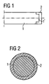
- a throttle valve produced by the method is shown in half in cross section in a simplified, schematic form.
- a circular disk-shaped preform 1 made of a first plastic is produced by injection molding in a first step.
- a ring 2 made of a second plastic is then arranged in a second step around the narrow side of the preform 1 by injection molding on the preform 1 and also brought to hardening.
- the width of the ring 2 is in the range of 1 to 3.5 mm. It is advantageous if in the first step at the Narrow side of the preform 1 a circumferential projection 1 'is arranged. By this measure, the bond between the pre-molded part 1 and the ring 2 is reinforced.
- a throttle valve with the pre-molded part 1 and the arranged ring 2 is shown in simplified form.
- a throttle valve is particularly suitable for use in a throttle body made of plastic.
Landscapes
- Engineering & Computer Science (AREA)
- General Engineering & Computer Science (AREA)
- Mechanical Engineering (AREA)
- Manufacturing & Machinery (AREA)
- Injection Moulding Of Plastics Or The Like (AREA)
- Fuel-Injection Apparatus (AREA)
Abstract
Description
- Die Erfindung bezieht sich auf ein Verfahren zur Herstellung einer Drosselklappe sowie auf einen Drosselklappenstutzen aus Kunststoff.
- Drosselklappen in Drosselklappenstutzen sind bekannt. In der
DE 195 12 729 A1 wird ein Drosselklappenstutzen mit einem rohrartigen Gehäuse beschrieben, in dem eine Drosselklappe auf einer Drosselklappenwelle befestigt ist, die quer zur Längsachse des rohrartigen Gehäuses an ihren freien Enden durch Ausnehmungen in der Gehäusewand durchführend drehbar gelagert ist. Bei der Anordnung der Drosselklappen in Drosselklappenstutzen ist oftmals nachteilig, dass aufgrund von teilweise extrem kleinen Leckage-Vorgaben mit hoher Präzision und Oberflächengüte gearbeitet werden muss, um eine Bildung von Leckluft zu vermeiden. Die Drosselklappe wird dabei in der Regel aus einem Blech gestanzt und mit großem Präzisionsaufwand feinst gedreht, wobei sehr geringe Toleranzen eingehalten werden müssen. Dabei muss darauf geachtet werden, dass die Drosselklappe möglichst dicht an der Innenwand des Drosselklappenstutzens anliegt, die Innenwand aber nicht zu fest berührt, da es sonst zu einem Verklemmen der Drosselklappe kommen kann. Zur Vereinfachung des Herstellungsverfahrens der Drosselklappe ist man inzwischen dazu übergegangen, die Drosselklappe aus Kunststoff zu fertigen. Aufgrund des Schrumpfverhaltens der dabei eingesetzten Kunststoffe ist es jedoch besonders schwierig, die erforderlichen Toleranzen einzuhalten. Eine Nachbearbeitung der aus Kunststoff gefertigten Drosselklappe ist daher in der Regel zwingend notwendig. - Ein zweistufiges Verfahren zur Drosselklappenherstellung ist aus der
WO 00/23701 GB 2 093 955 A - In beiden Dokumenten ist jedoch am Rand der Drosselklappe ein flexibles Material als Dichtungsrand beziehungsweise Dichtlippe vorgesehen.
- Die Anbringung eines separat hergestellten Dichtelements an Drosselklappenflügeln ist aus der
EP 1 028 238 A2 bekannt, während dieDE 43 29 526 A1 das Anspritzen von Dichtmaterial an einem Drosselklappenflügel in bestimmten Zonen beschreibt. Schließlich sind aus Altmann O. "Drosselklappen in Serie, Kunststoff-Drosselklappen im Ausgangskanal sind möglich", Kunststoffe, Carl Hanser Verlag München, Werkstoffe für in einem einzigen Schritt aus Kunststoff hergestellte Drosselklappen bekannt, wobei eine Klappe mit einer Breite von 3 mm offenbart ist. - Der Erfindung liegt daher die Aufgabe zugrunde, ein Verfahren zur Herstellung einer Drosselklappe zu schaffen, bei welchem die geforderten Toleranzen für die Drosselklappe eingehalten werden.
- Die der Erfindung zugrunde liegende Aufgabe wird durch ein Verfahren zur Herstellung einer Drosselklappe mit den Merkmalen des Anspruches 1 und durch einen Drosselklappenstutzen mit einer Drosselklappe nach Anspruch 4 gelöst. Als erster und als zweiter Kunststoff können dabei Kunststoffe eingesetzt werden, die durch Spritzgießen verarbeitet werden können und die eine Temperaturbeständigkeit bis zu 150° C aufweisen. Bei dem eigentlichen Spritzgießen werden Mehrkomponentenwerkzeuge eingesetzt. Es hat sich in überraschender Weise gezeigt, dass das Problem des relativ starken Schrumpfens von Kunststoff durch das im Anspruch 1 ausgeführte zweistufige Spritzgießverfahren vermieden werden kann. Dies wird dadurch erreicht, dass der größte Teil der Schrumpfung am Vorspritzling erfolgt, der im ersten Schritt des Verfahrens hergestellt wird. Die Schrumpfung des anschließend im zweiten Schritt anzuordnenden Ringes ist deutlich geringer, so dass die erforderlichen Toleranzen auf relativ einfache Weise eingestellt werden können, wobei eine Nachbearbeitung der fertigen Drosselklappe nicht erforderlich ist. Das Verfahren ist darüber hinaus relativ einfach und kostengünstig durchzuführen.
- Eine wesentliche Eigenschaft des erfindungsgemäßen Verfahrens besteht darin, dass als erster Kunststoff ein mit Füllstoffen versetztes Polyphenylensulfid oder ein mit Füllstoffen versetztes Polyphtalamid oder ein mit Glasfasern versetztes Polybuthylenterephthalat oder ein mit Glasfasern versetztes Polyetherketon oder ein mit Glasfasern versetztes Polyamid und als zweiter Kunststoff der erste Kunststoff eingesetzt werden. Bei den Füllstoffen handelt es sich in der Regel um eine Mischung aus Glasfasern und Mineralstoffen. Ihr Anteil liegt dabei in der Regel über 60 Gew.-%. Dabei ist vorteilhaft, dass die Drosselklappe eine relativ hohe Härte aufweist und gleichzeitig am Rand etwas weicher ist, was der Einhaltung der erforderlichen engen Toleranzen zugute kommt. Der Anteil an Glasfasern kann beispielsweise bei 30 oder 50 Gew.-% liegen. Der Einsatz jeweils gleicher Kunststoffe im ersten Schritt sowie im zweiten Schritt des Verfahrens vereinfacht die Durchführung des Verfahrens, wobei eine Vermeidung von Leckluft in ausreichendem Maße sichergestellt ist. Nach einem weiteren Merkmal wird im zweiten Schritt ein Ring mit einer Breite von 1 bis 3,5 mm angeordnet. Eine bevorzugte Breite des Rings beträgt dabei 3 mm. Bei dieser Ringbreite ist nur eine relativ geringe Schrumpfung des Kunststoffes in der Abkühlphase zu verzeichnen, was die Einhaltung der niedrigen Toleranzen in besonderem Maße vereinfacht.
- Nach einer weiteren Ausgestaltung der Erfindung wird als erster und als zweiter Kunststoff ein mit Füllstoffen versetztes Polyphenylensulfid mit einem Anteil an Füllstoffen von 64 bis 66 Gew.-% eingesetzt. Dadurch lässt sich die Bildung von Leckluft nahezu vollständig vermeiden. Gleichzeitig ist eine relativ hohe Härte der Drosselklappe sichergestellt.
- Gemäß einer weiteren bevorzugten Ausgestaltung der Erfindung ist vorgesehen, dass im ersten Schritt an der Schmalseite des Vorspritzlings ein umlaufender Vorsprung angeordnet wird. Dieser umlaufende Vorsprung verläuft in der Regel mittig. Die Bildung des Vorsprungs im ersten Schritt erleichtert die Bindung zwischen dem Vorspritzling und dem Ring, der im zweiten Schritt um die Schmalseite des Vorspritzlings durch Spritzgießen angeordnet wird.
- In neuester Zeit geht man dazu über, den Drosselklappenstutzen nicht mehr aus Gussmaterial, sondern aus Kunststoff zu fertigen. Aufgrund der Materialaffinität eignet sich eine erfindungsgemäß hergestellte Drosselklappe besonders für die Anordnung in einem Drosselklappenstutzen aus Kunststoff.
- Die Erfindung wird nachfolgend anhand der Zeichnung (
Fig. 1, Fig. 2 ) näher und beispielhaft erläutert. - Fig. 1
- zeigt eine nach dem Verfahren hergestellte Drosselklappe hälftig im Querschnitt.
- Fig. 2
- zeigt eine nach dem Verfahren hergestellte Drosselklappe in der Draufsicht.
- In
Fig. 1 ist eine nach dem Verfahren hergestellte Drosselklappe hälftig im Querschnitt in vereinfachter, schematischer Form dargestellt. Bei dem Verfahren zur Herstellung einer Drosselklappe wird in einem ersten Schritt ein kreisrunder scheibenförmiger Vorspritzling 1 aus einem ersten Kunststoff durch Spritzgießen hergestellt. Nach Aushärtung des Vorspritzlings 1 wird anschließend in einem zweiten Schritt ein Ring 2 aus einem zweiten Kunststoff um die Schmalseite des Vorspritzlings 1 durch Spritzgießen an dem Vorspritzling 1 angeordnet und ebenfalls zur Aushärtung gebracht. Die Breite des Ringes 2 liegt im Bereich von 1 bis 3,5 mm. Dabei ist vorteilhaft, wenn im ersten Schritt an der Schmalseite des Vorspritzlings 1 ein umlaufender Vorsprung 1' angeordnet wird. Durch diese Maßnahme wird die Bindung zwischen dem Vorspritzling 1 und dem Ring 2 verstärkt. - In
Fig. 2 ist die Draufsicht auf eine Drosselklappe mit dem Vorspritzling 1 und dem angeordneten Ring 2 vereinfacht dargestellt. Eine solche Drosselklappe eignet sich besonders für den Einsatz in einem Drosselklappenstutzen aus Kunststoff.
Claims (4)
- Verfahren zur Herstellung einer Drosselklappe, bei dem in einem ersten Schritt ein kreisrunder, scheibenförmiger Vorspritzling (1) aus einem ersten Kunststoff durch Spritzgießen hergestellt wird, und anschließend nach Aushärtung des Vorspritzlings (1) in einem zweiten Schritt ein Ring (2) aus einem zweiten Kunststoff um die Schmalseite des Vorspritzlings (1) durch Spritzgießen an dem Vorspritzling (1) angeordnet wird und ebenfalls zur Aushärtung gebracht wird, dadurch gekennzeichnet, dass im zweiten Schritt der Ring (2) mit einer Breite von 1 bis 3,5 mm angeordnet wird und als erster Kunststoff ein mit Füllstoffen versetztes Polyphenylensulfid oder ein mit Füllstoffen versetztes Polyphtalamid oder ein mit Glasfasern versetztes Polybuthylenterephthalat oder ein mit Glasfasern versetztes Polyetherketon oder ein mit Glasfasern versetztes Polyamid und als zweiter Kunststoff der jeweils erste Kunststoff eingesetzt wird.
- Verfahren nach Anspruch 1, bei dem als erster und als zweiter Kunststoff ein mit Füllstoffen versetztes Polyphenylensulfid mit einem Anteil an Füllstoffen von 64 bis 66 Gew.-% eingesetzt wird.
- Verfahren nach Anspruch 1 oder 2, bei dem im ersten Schritt an der Schmalseite des Vorspritzlings (1) ein umlaufender Vorsprung (1') angeordnet wird.
- Drosselklappenstutzen aus Kunststoff mit einer Drosselklappe, die aus einem Vorspritzling (1) aus einem ersten spritzgegossenen Kunststoff und einem Ring (2) aus einem zweiten spritzgegossenen Kunststoff besteht, wobei der Ring (2) um die Schmalseite des Vorspritzlings (1) angeordnet ist, dadurch gekennzeichnet, dass der Ring eine Breite von 1 bis 3,5 mm aufweist und der erste Kunststoff ein mit Füllstoffen versetztes Polyphenylensulfid oder ein mit Füllstoffen versetztes Polyphtalamid oder ein mit Glasfasern versetztes Polybuthylenterephthalat oder ein mit Glasfasern versetztes Polyetherketon oder ein mit Glasfasern versetztes Polyamid und der zweite Kunststoff der jeweils erste Kunststoff ist.
Applications Claiming Priority (3)
| Application Number | Priority Date | Filing Date | Title |
|---|---|---|---|
| DE10255339A DE10255339A1 (de) | 2002-11-27 | 2002-11-27 | Verfahren zur Herstellung einer Drosselklappe |
| DE10255339 | 2002-11-27 | ||
| PCT/DE2003/003290 WO2004048066A1 (de) | 2002-11-27 | 2003-10-02 | Verfahren zur herstellung einer drosselklappe |
Publications (2)
| Publication Number | Publication Date |
|---|---|
| EP1565298A1 EP1565298A1 (de) | 2005-08-24 |
| EP1565298B1 true EP1565298B1 (de) | 2009-03-04 |
Family
ID=32308753
Family Applications (1)
| Application Number | Title | Priority Date | Filing Date |
|---|---|---|---|
| EP03770892A Expired - Lifetime EP1565298B1 (de) | 2002-11-27 | 2003-10-02 | Verfahren zur herstellung einer drosselklappe und drosselklappenstutzen mit einer drosselklappe |
Country Status (5)
| Country | Link |
|---|---|
| US (1) | US20050206036A1 (de) |
| EP (1) | EP1565298B1 (de) |
| BR (1) | BR0315631A (de) |
| DE (2) | DE10255339A1 (de) |
| WO (1) | WO2004048066A1 (de) |
Cited By (1)
| Publication number | Priority date | Publication date | Assignee | Title |
|---|---|---|---|---|
| RU2845258C1 (ru) * | 2024-08-13 | 2025-08-15 | Андрей Викторович Литвиненко | Способ изготовления сепаратора полимерного для подшипников |
Families Citing this family (3)
| Publication number | Priority date | Publication date | Assignee | Title |
|---|---|---|---|---|
| US7048001B2 (en) * | 2004-04-13 | 2006-05-23 | Nelson Irrigation Corporation | Pressure regulator with single strut regulator seat |
| JP4434138B2 (ja) * | 2005-12-20 | 2010-03-17 | 株式会社デンソー | バルブユニットの製造方法及び組付方法 |
| ITMC20070062A1 (it) * | 2007-03-28 | 2008-09-29 | O M C E Di Rocchetti Amleto Spa | Rubinetto o valvola a farfalla, in particolare per serbatoi. |
Family Cites Families (14)
| Publication number | Priority date | Publication date | Assignee | Title |
|---|---|---|---|---|
| DE1755596A1 (de) * | 1968-05-27 | 1971-11-18 | Liverpa Gmbh | Profilleiste fuer Kraftfahrzeuge |
| DE2905617A1 (de) * | 1979-02-14 | 1980-08-21 | Daimler Benz Ag | Rueckschlagklappenventil, insbesondere zur entlueftung von fahrgastraeumen von personenkraftwagen |
| GB2093955A (en) * | 1981-02-25 | 1982-09-08 | Clearplas Ltd | Fluid flow controlling valves |
| JPH032015A (ja) * | 1989-05-31 | 1991-01-08 | Daikyo Inc | 通気用フラップの製造方法 |
| US5163773A (en) * | 1991-06-07 | 1992-11-17 | General Motors Corporation | Self-locking ball-and-socket mechanism |
| FR2692622B1 (fr) * | 1992-06-17 | 1994-09-16 | Solex | Organe d'étranglement rotatif pour installation d'alimentation de moteur à combustion interne et corps de papillon en comportant application. |
| DE4329526A1 (de) * | 1993-09-02 | 1995-03-09 | Mann & Hummel Filter | Drosseleinrichtung |
| DE4423370A1 (de) * | 1994-07-04 | 1996-01-11 | Bayerische Motoren Werke Ag | Drosselklappen-Stutzen für eine Brennkraftmaschine |
| DE19706734C2 (de) * | 1997-02-20 | 2000-11-02 | Opel Adam Ag | Entlüftungsvorrichtung und Verfahren zu ihrer Herstellung |
| DE19848440A1 (de) * | 1998-10-21 | 2000-04-27 | Mann & Hummel Filter | Klappenmechanismus |
| US6135418A (en) * | 1999-02-10 | 2000-10-24 | Eaton Corporation | Low-leakage air valve for variable air intake system |
| JP2001198955A (ja) * | 2000-01-18 | 2001-07-24 | Denso Corp | 通風路切替用ドアの製造方法 |
| JP4300340B2 (ja) * | 2000-02-14 | 2009-07-22 | 株式会社デンソー | 通風路切替用ドア |
| JP3971898B2 (ja) * | 2000-05-25 | 2007-09-05 | 株式会社日立製作所 | スロットルボディ |
-
2002
- 2002-11-27 DE DE10255339A patent/DE10255339A1/de not_active Withdrawn
-
2003
- 2003-10-02 DE DE50311253T patent/DE50311253D1/de not_active Expired - Lifetime
- 2003-10-02 WO PCT/DE2003/003290 patent/WO2004048066A1/de not_active Ceased
- 2003-10-02 EP EP03770892A patent/EP1565298B1/de not_active Expired - Lifetime
- 2003-10-02 BR BR0315631-1A patent/BR0315631A/pt not_active IP Right Cessation
-
2005
- 2005-04-22 US US11/111,950 patent/US20050206036A1/en not_active Abandoned
Cited By (2)
| Publication number | Priority date | Publication date | Assignee | Title |
|---|---|---|---|---|
| RU2845258C1 (ru) * | 2024-08-13 | 2025-08-15 | Андрей Викторович Литвиненко | Способ изготовления сепаратора полимерного для подшипников |
| RU2845258C9 (ru) * | 2024-08-13 | 2025-09-29 | Андрей Викторович Литвиненко | Способ изготовления сепаратора полимерного для подшипников |
Also Published As
| Publication number | Publication date |
|---|---|
| US20050206036A1 (en) | 2005-09-22 |
| WO2004048066A1 (de) | 2004-06-10 |
| BR0315631A (pt) | 2005-08-23 |
| DE10255339A1 (de) | 2004-06-09 |
| DE50311253D1 (de) | 2009-04-16 |
| EP1565298A1 (de) | 2005-08-24 |
Similar Documents
| Publication | Publication Date | Title |
|---|---|---|
| EP1514032B1 (de) | Zwei-komponenten lagerschale für ein umspritztes kugelgelenk | |
| DE102014206870B4 (de) | Lageranordnung und Verfahren zu ihrer Herstellung | |
| DE2753170A1 (de) | Wellendichtung und verfahren zu ihrer herstellung | |
| EP1565298B1 (de) | Verfahren zur herstellung einer drosselklappe und drosselklappenstutzen mit einer drosselklappe | |
| EP0898056A2 (de) | Abdichtung für relativ zueinander hin- und hergehende Maschinenteile | |
| DE10349232B4 (de) | Durch Extrusion geformtes Fahrzeugteil und Verfahren zu dessen Herstellung | |
| DE102013220800B3 (de) | Getrieberad sowie Verfahren und Werkzeug zum Herstellen eines Getrieberads | |
| EP2803792B1 (de) | Schlüssel zum Betätigen eines Schließzylinders sowie Verfahren zur Herstellung des Schlüssels | |
| DE102013100417A1 (de) | Zahnradeinheit | |
| EP2053484B1 (de) | Stellknopf | |
| AT514254B1 (de) | Verfahren zur Herstellung eines Schlüssels sowie eine Vorrichtung zur Durchführung des Verfahrens | |
| EP1498911B1 (de) | Ringmagnet | |
| DE4329526A1 (de) | Drosseleinrichtung | |
| EP0727089B1 (de) | Elektromechanisches bauelement, insbesondere relais, mit dichtem gehäuse | |
| WO2024141140A1 (de) | Ventil zur verwendung in einem fahrzeug-kühlkreislauf sowie verfahren zur herstellung eines derartigen ventils | |
| EP1907715B9 (de) | HÜLSE, INSBESONDERE AUßENHÜLSE FÜR EIN ELASTOMERLAGER, UND VERWENDUNG EINER DERARTIGEN HÜLSE IN EINEM ELASTOMERLAGER | |
| EP1386713B2 (de) | Kunststoff-Spritzguss-Formteil | |
| EP3430288B1 (de) | Stellspindelanordnung für einen linearantrieb | |
| DE102022105648B3 (de) | Verfahren zur Herstellung eines Kunststoffbauteils mit einem Trägerteil und einer darauf aufgebrachten Deckschicht t und verfahrensgemäß hergestelltes Kunststoffbauteil | |
| EP1488142A1 (de) | Dichtungselement | |
| DE102020101075A1 (de) | Mehrkomponentenzahnrad | |
| DE102018207766A1 (de) | Lenkgetriebe und Verfahren zur Herstellung des Lenkgetriebes | |
| DE10333898B3 (de) | Verfahren zur Herstellung von hinterspritzten Formteilen mit unterschiedlichen Wanddicken und Größen | |
| DE102018218557A1 (de) | Lenkgetriebe und Verfahren zur Herstellung des Lenkgetriebes | |
| EP3266585A1 (de) | Kunststoffverzahnungsteil |
Legal Events
| Date | Code | Title | Description |
|---|---|---|---|
| PUAI | Public reference made under article 153(3) epc to a published international application that has entered the european phase |
Free format text: ORIGINAL CODE: 0009012 |
|
| 17P | Request for examination filed |
Effective date: 20050317 |
|
| AK | Designated contracting states |
Kind code of ref document: A1 Designated state(s): AT BE BG CH CY CZ DE DK EE ES FI FR GB GR HU IE IT LI LU MC NL PT RO SE SI SK TR |
|
| AX | Request for extension of the european patent |
Extension state: AL LT LV MK |
|
| DAX | Request for extension of the european patent (deleted) | ||
| RBV | Designated contracting states (corrected) |
Designated state(s): DE FR IT |
|
| RIN1 | Information on inventor provided before grant (corrected) |
Inventor name: SEEGER, ARMIN |
|
| 17Q | First examination report despatched |
Effective date: 20060328 |
|
| RAP1 | Party data changed (applicant data changed or rights of an application transferred) |
Owner name: CONTINENTAL AUTOMOTIVE GMBH |
|
| RTI1 | Title (correction) |
Free format text: METHOD FOR PRODUCING A THROTTLE VALVE AND THROTTLE VALVE SUPPORT WITH A THROTTLE VALVE |
|
| GRAP | Despatch of communication of intention to grant a patent |
Free format text: ORIGINAL CODE: EPIDOSNIGR1 |
|
| GRAS | Grant fee paid |
Free format text: ORIGINAL CODE: EPIDOSNIGR3 |
|
| GRAA | (expected) grant |
Free format text: ORIGINAL CODE: 0009210 |
|
| AK | Designated contracting states |
Kind code of ref document: B1 Designated state(s): DE FR IT |
|
| REF | Corresponds to: |
Ref document number: 50311253 Country of ref document: DE Date of ref document: 20090416 Kind code of ref document: P |
|
| PLBE | No opposition filed within time limit |
Free format text: ORIGINAL CODE: 0009261 |
|
| STAA | Information on the status of an ep patent application or granted ep patent |
Free format text: STATUS: NO OPPOSITION FILED WITHIN TIME LIMIT |
|
| 26N | No opposition filed |
Effective date: 20091207 |
|
| PGFP | Annual fee paid to national office [announced via postgrant information from national office to epo] |
Ref country code: FR Payment date: 20121031 Year of fee payment: 10 |
|
| PGFP | Annual fee paid to national office [announced via postgrant information from national office to epo] |
Ref country code: IT Payment date: 20121025 Year of fee payment: 10 |
|
| REG | Reference to a national code |
Ref country code: FR Ref legal event code: ST Effective date: 20140630 |
|
| PG25 | Lapsed in a contracting state [announced via postgrant information from national office to epo] |
Ref country code: IT Free format text: LAPSE BECAUSE OF NON-PAYMENT OF DUE FEES Effective date: 20131002 Ref country code: FR Free format text: LAPSE BECAUSE OF NON-PAYMENT OF DUE FEES Effective date: 20131031 |
|
| PGFP | Annual fee paid to national office [announced via postgrant information from national office to epo] |
Ref country code: DE Payment date: 20161031 Year of fee payment: 14 |
|
| REG | Reference to a national code |
Ref country code: DE Ref legal event code: R119 Ref document number: 50311253 Country of ref document: DE |
|
| PG25 | Lapsed in a contracting state [announced via postgrant information from national office to epo] |
Ref country code: DE Free format text: LAPSE BECAUSE OF NON-PAYMENT OF DUE FEES Effective date: 20180501 |