EP1564762B1 - Liquid-cooled choke - Google Patents
Liquid-cooled choke Download PDFInfo
- Publication number
- EP1564762B1 EP1564762B1 EP05100872A EP05100872A EP1564762B1 EP 1564762 B1 EP1564762 B1 EP 1564762B1 EP 05100872 A EP05100872 A EP 05100872A EP 05100872 A EP05100872 A EP 05100872A EP 1564762 B1 EP1564762 B1 EP 1564762B1
- Authority
- EP
- European Patent Office
- Prior art keywords
- choke
- cooling
- profile
- core
- cooling profile
- Prior art date
- Legal status (The legal status is an assumption and is not a legal conclusion. Google has not performed a legal analysis and makes no representation as to the accuracy of the status listed.)
- Expired - Lifetime
Links
Images
Classifications
-
- H—ELECTRICITY
- H01—ELECTRIC ELEMENTS
- H01F—MAGNETS; INDUCTANCES; TRANSFORMERS; SELECTION OF MATERIALS FOR THEIR MAGNETIC PROPERTIES
- H01F27/00—Details of transformers or inductances, in general
- H01F27/08—Cooling; Ventilating
- H01F27/10—Liquid cooling
-
- H—ELECTRICITY
- H01—ELECTRIC ELEMENTS
- H01F—MAGNETS; INDUCTANCES; TRANSFORMERS; SELECTION OF MATERIALS FOR THEIR MAGNETIC PROPERTIES
- H01F37/00—Fixed inductances not covered by group H01F17/00
-
- H—ELECTRICITY
- H05—ELECTRIC TECHNIQUES NOT OTHERWISE PROVIDED FOR
- H05K—PRINTED CIRCUITS; CASINGS OR CONSTRUCTIONAL DETAILS OF ELECTRIC APPARATUS; MANUFACTURE OF ASSEMBLAGES OF ELECTRICAL COMPONENTS
- H05K7/00—Constructional details common to different types of electric apparatus
- H05K7/20—Modifications to facilitate cooling, ventilating, or heating
Definitions
- the invention relates to a liquid-cooled choke comprising a choke core, a choke coil and a path for a cooling liquid to cool the choke wherein the choke core is divided into at least two parts arranged in a cooling profile to which the path for the cooling liquid is arranged and which at the same time provides the choke with a frame and an assembly jig.
- US Patent 1790906 discloses a known solution where a two-piece coil is encapsulated such that a cooling liquid is circulated between the adjacent coils and on their edges in water channels arranged in the middle and ends of the encapsulation.
- the implementation is relatively complex, and only the coil will be cooled in this way.
- Typical of the former structures is that the cooling is in one way or another implemented in connection with the coil. These implementations also make the assembly and structure of the choke difficult and complex.
- the choke core is formed of two plate packs and the cooling profile comprises recesses for the plate packs on two opposing sides of the profile, whereby the cooling profile extends in between the plate packs and from there to two sides of each plate pack, and around the sides of the cooling profile covering the plate packs and the two bare sides of the plate packs there is an insulation and on top of the insulation there is the choke coil.
- the choke core is formed of three plate packs, and the cooling profile comprises on its edges or circumference recesses for the plate packs at regular intervals, the plate packs being symmetrically arranged with respect to the central axis of the cooling profile, whereby the cooling profile extends into the middle of the plate packs and from there to two sides of each plate pack, and around the profile parts between the plate packs and the bare sides of each plate pack there is an insulation and on top of the insulation there is the choke coil.
- This solution enables a more efficient cooling both for the core and the coil.
- the plate packs can be shortened and, if desired, three chokes can be arranged in the same cooling profile column by only insulating the core plate packs from each other, which saves material and space.
- the choke core is formed of three columns and the cooling profile comprises three openings on the same circular arch at regular intervals, into which the columns are positioned, the surfaces of the columns being lined with an insulation and a coil arranged on top of the insulation.
- three separate chokes are in a way connected to the same cooling body of the invention to form one choke unit. If chokes are used, for instance, in the branches of an IGBT module, three three-column chokes are needed for one converter. Correspondingly, nine "one-column" chokes according to the first implementation are needed.
- the path of the cooling liquid to the cooling profile is preferably arranged symmetrically in the middle of the choke core parts, the material of the cooling profile being preferably aluminium or a mixture thereof. If required, at desired points the cooling profile can be provided with additional cooling channels according to cooling power demand.
- the output of an inverter typically comprises an output choke as a part of the filter to limit du/dt, i.e. change of voltage (u) with respect to time (t), and common mode currents, which further cause bearing currents and insulation load on the motor.
- the choke is a yoke-free type of choke.
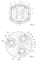
- Figure 1 shows a "one-column" liquid-cooled choke of the invention, comprising a choke core 1, a choke coil 2 and a path 3 for a cooling liquid to cool the choke.
- the choke core is divided into two parts 1a and 1b arranged in a cooling profile 4 to which the path 3 for the cooling liquid is arranged and which at the same time provides the choke with a frame and an assembly jig, as will be described in the following.
- the divided choke core 1 is formed of two identical iron plate packs 1a and 1b, for which the cooling profile 4 comprises accurately dimensioned recesses 5 on its two opposing sides.
- the plates of the plate packs 1a and 1b are piled into the recesses 5 so that the cooling profile 4 extends in between the plate packs 1a and 1b and from there to two sides of each plate pack 1a and 1b, having a tight contact with the plate packs 1a and 1b.
- an insulation 6 is wrapped around the sides of the cooling profile 4 covering these plate or core packs 1a and 1b and around the two bare sides, i.e. sides not covered with the cooling profile 4, of the core packs 1a and 1b, and the choke coil 2 made of profiled copper is coiled on top of the insulation.
- the packet thus formed is insulated and lacquered.
- the path for the cooling liquid is here a channel 3 bored into the cooling profile 4 or formed in the extrusion phase, passing through the cooling profile 4 in the middle of the core packs 1a and 1b. Only two connections, input and output, are needed to circulate the cooling liquid. In this way, the core packs 1a and 1b are cooled effectively, and since the majority of the coil 2 is on top of the cooling profile 4, the effective cooling of the coil 2 is also secured.
- the material of the cooling profile 4 is preferably aluminium or a suitable mixture thereof.
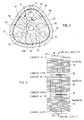
- the choke shown in Figure 2 differs from the structure of Figure 1 primarily in that the choke core 10 is formed of three plate packs 10a, 10b and 10c.
- the cooling profile 40 comprises on its edges or circumference at regular intervals recesses 50 for the plate packs 10a, 10b and 10c, which are formed as in Figure 1 .
- the plate packs 10a, 10b and 10c are arranged symmetrically with respect to the central axis of the cooling profile 40, and the cooling profile 40 extends into the middle of the plate pacts 10a, 10b and 10c and from there to two sides of each plate pack.
- an insulation 60 is arranged around the profile parts between the plate packs 10a, 10b and 10c and around the bare side of each plate pack 10a, 10b and 10c and a choke coil 20 is arranged on top of the insulation.
- a path 30 for a cooling liquid is a channel 30 bored into the cooling profile 40 or formed in the extrusion phase, passing through the cooling profile 40 in the middle of the plate packs 10a, 10b and 10c.
- the figure shows feasible additional cooling channels 31, which may be located between each two core packs, for instance. These channels 31 can be connected to the main channel 30 by means of connecting channels 32.
- the cross section of the cooling profile 40 is preferably an intermediate form between a triangle and a circle, where no sharp angles are present and the coiling is easy to implement.
- the solution of Figure 2 enables a more efficient cooling for both the core plate packs 10a, 10b and 10c and the coil 20, as was already stated in the beginning.
- the plate packs 10a, 10b and 10c can be shortened and, if desired, three different chokes can be arranged according to Figure 3 in the same cooling profile column 41 by only insulating the plate packs 10a, 10b and 10c of the chokes from each other by means of insulations 70.
- Measurements have shown that crosstalk takes place so that the current of the middlemost, also hottest, branch of the IGBT module decreases suitably. Crosstalk can be controlled by changing the distance of the coils 20.
- the choke provided with the cooling profiles 4 and 40 not only eliminates problems associated with cooling but also prevents the twisting of the iron core pack in conventional chokes, while the coil is coiled around it. It is, namely, difficult to coil thick profiled copper around the plate pack provided only with corner supports in such a manner that the pack will not be twisted.
- Compromises with respect to the cross-sectional surface of the coil 2 and 20 can be made with an efficient cooling.
- the reduction of the cross-sectional surface increases resistance, which is, up to a certain extent, useful in the yoke-free output choke of the inverter.
- FIG. 4 shows a third implementation of the choke of the invention.
- a choke core 100 is formed of three columns 100a, 100b and 100c, and a cooling profile 140 comprises three openings 150 on the same circular arch at regular intervals, into which the columns are positioned, the surfaces of the columns being lined with an insulation 160 and a coil 120 arranged on top of the insulation.
- three separate chokes are in a way connected to the same cooling body of the invention to form one choke unit, as was already stated in the beginning.
- the path for the cooling liquid is arranged in the cooling profile as a channel 130 extending in the middle of the choke core parts, as was the case also in Figures 1 and 2 , and the cooling profile is preferably made of aluminium or an aluminium mixture.
Landscapes
- Engineering & Computer Science (AREA)
- Power Engineering (AREA)
- Physics & Mathematics (AREA)
- Thermal Sciences (AREA)
- Microelectronics & Electronic Packaging (AREA)
- Transformer Cooling (AREA)
- Coils Or Transformers For Communication (AREA)
- Coils Of Transformers For General Uses (AREA)
- Separation By Low-Temperature Treatments (AREA)
- Fuses (AREA)
- Fats And Perfumes (AREA)
Applications Claiming Priority (2)
| Application Number | Priority Date | Filing Date | Title |
|---|---|---|---|
| FI20040230 | 2004-02-13 | ||
| FI20040230A FI118397B (fi) | 2004-02-13 | 2004-02-13 | Nestejäähdytetty kuristin |
Publications (3)
| Publication Number | Publication Date |
|---|---|
| EP1564762A2 EP1564762A2 (en) | 2005-08-17 |
| EP1564762A3 EP1564762A3 (en) | 2006-03-22 |
| EP1564762B1 true EP1564762B1 (en) | 2012-05-09 |
Family
ID=31725708
Family Applications (1)
| Application Number | Title | Priority Date | Filing Date |
|---|---|---|---|
| EP05100872A Expired - Lifetime EP1564762B1 (en) | 2004-02-13 | 2005-02-09 | Liquid-cooled choke |
Country Status (4)
| Country | Link |
|---|---|
| US (1) | US7245197B2 (fi) |
| EP (1) | EP1564762B1 (fi) |
| AT (1) | ATE557404T1 (fi) |
| FI (1) | FI118397B (fi) |
Families Citing this family (5)
| Publication number | Priority date | Publication date | Assignee | Title |
|---|---|---|---|---|
| US7129808B2 (en) * | 2004-09-01 | 2006-10-31 | Rockwell Automation Technologies, Inc. | Core cooling for electrical components |
| US7508289B1 (en) | 2008-01-11 | 2009-03-24 | Ise Corporation | Cooled high power vehicle inductor and method |
| FI122043B (fi) | 2008-08-13 | 2011-07-29 | Abb Oy | Taajuusmuuttajan kuristinlaite |
| EP3288046B1 (de) * | 2016-08-25 | 2021-04-14 | Siemens Aktiengesellschaft | Spulenvorrichtung |
| DE102017222243A1 (de) * | 2017-12-08 | 2019-06-13 | Zf Friedrichshafen Ag | Drossel mit Kühlvorrichtung |
Family Cites Families (13)
| Publication number | Priority date | Publication date | Assignee | Title |
|---|---|---|---|---|
| US2547045A (en) * | 1947-12-04 | 1951-04-03 | Ohio Crankshaft Co | Means for cooling magnetic cores of electrical apparatus |
| GB732841A (en) | 1952-08-22 | 1955-06-29 | British Thomson Houston Co Ltd | Improvements relating to electric induction apparatus |
| US3299383A (en) * | 1965-11-04 | 1967-01-17 | Westinghouse Electric Corp | Current transformer having fluid carry passages in high voltage conductor |
| GB1595094A (en) | 1977-10-19 | 1981-08-05 | Gen Electric | Method and system for cooling electrical apparatus |
| US4337569A (en) * | 1978-02-27 | 1982-07-06 | General Electric Company | Method of making integrally formed transformer cooling ducts |
| DE3522740A1 (de) | 1985-04-12 | 1986-10-23 | BCL-Lichttechnik Inh. Claudia C. Berger, 8000 München | Ringkerntransformator oder -drossel |
| JPS62141711A (ja) * | 1985-12-16 | 1987-06-25 | Mitsubishi Electric Corp | 変流器 |
| JP2553157B2 (ja) | 1988-08-03 | 1996-11-13 | 株式会社東芝 | 静止誘導機器 |
| DE3843807A1 (de) | 1988-12-24 | 1990-07-12 | Lahmeyer Ag Fuer Energiewirtsc | Selbstgekuehlter hochspannungstransformator |
| DE4017750A1 (de) | 1990-06-01 | 1991-12-05 | Abb Patent Gmbh | Fluessigkeitsgekuehlte drosselspule |
| DE9307081U1 (de) * | 1993-05-10 | 1993-07-01 | Siemens AG, 8000 München | Flüssigkeitsgekühlte Ventildrossel |
| US6157282A (en) * | 1998-12-29 | 2000-12-05 | Square D Company | Transformer cooling method and apparatus therefor |
| DE10117847C1 (de) | 2001-04-04 | 2003-02-06 | Siemens Ag | Transformator mit forcierter Flüssigkeitskühlung |
-
2004
- 2004-02-13 FI FI20040230A patent/FI118397B/fi not_active IP Right Cessation
-
2005
- 2005-01-31 US US11/045,520 patent/US7245197B2/en not_active Expired - Fee Related
- 2005-02-09 AT AT05100872T patent/ATE557404T1/de active
- 2005-02-09 EP EP05100872A patent/EP1564762B1/en not_active Expired - Lifetime
Also Published As
| Publication number | Publication date |
|---|---|
| FI118397B (fi) | 2007-10-31 |
| FI20040230L (fi) | 2005-08-14 |
| US20050179513A1 (en) | 2005-08-18 |
| EP1564762A3 (en) | 2006-03-22 |
| FI20040230A0 (fi) | 2004-02-13 |
| EP1564762A2 (en) | 2005-08-17 |
| US7245197B2 (en) | 2007-07-17 |
| ATE557404T1 (de) | 2012-05-15 |
Similar Documents
| Publication | Publication Date | Title |
|---|---|---|
| US7034648B2 (en) | Amorphous metal core transformer | |
| EP2406798B1 (en) | An electric transformer with improved cooling system | |
| US4326181A (en) | High voltage winding for dry type transformer | |
| US3659239A (en) | Power transformer incorporating improved heat dissipation means | |
| US4902998A (en) | Inductor assembly with cooled winding turns | |
| DE10348214A1 (de) | Elektromotor mit konzentrierter Wicklung und optimierter Wicklungskühlung und Schlitzfüllung | |
| EP0407167B1 (en) | Bus bar for power supply | |
| EP1564762B1 (en) | Liquid-cooled choke | |
| EA001129B1 (ru) | Вращающаяся электрическая машина с радиальным охлаждением | |
| WO1998034239A1 (en) | Horizontal air-cooling in a transformer | |
| US5866960A (en) | Gas-cooled electrical machine | |
| JP5845931B2 (ja) | セグメントコイル、ステータ及びセグメントコイルの製造方法、ステータの製造方法 | |
| EP0040262B1 (en) | Electrical reactor with foil windings | |
| KR102626342B1 (ko) | 인덕터 및 이를 포함하는 직류 컨버터 | |
| US4477791A (en) | Spacer block pattern for electrical inductive apparatus | |
| CN201044200Y (zh) | 换位导线 | |
| EP2187409B1 (en) | Double active parts structure of reactor | |
| US3668584A (en) | Electrical power apparatus | |
| CN113972049A (zh) | 开关电源变压器 | |
| JPH0992557A (ja) | 計器用変圧器の一次巻線 | |
| JPH08213254A (ja) | 静止誘導電気機器 | |
| GB2126059A (en) | Multilayer cylindrical induction coil | |
| JPH0341446Y2 (fi) | ||
| WO1998041998A1 (en) | A transformer winding structure and profiled conductive strip for the same | |
| JPH06244034A (ja) | 油入誘導電器の冷却方法および構造 |
Legal Events
| Date | Code | Title | Description |
|---|---|---|---|
| PUAI | Public reference made under article 153(3) epc to a published international application that has entered the european phase |
Free format text: ORIGINAL CODE: 0009012 |
|
| AK | Designated contracting states |
Kind code of ref document: A2 Designated state(s): AT BE BG CH CY CZ DE DK EE ES FI FR GB GR HU IE IS IT LI LT LU MC NL PL PT RO SE SI SK TR |
|
| AX | Request for extension of the european patent |
Extension state: AL BA HR LV MK YU |
|
| PUAL | Search report despatched |
Free format text: ORIGINAL CODE: 0009013 |
|
| AK | Designated contracting states |
Kind code of ref document: A3 Designated state(s): AT BE BG CH CY CZ DE DK EE ES FI FR GB GR HU IE IS IT LI LT LU MC NL PL PT RO SE SI SK TR |
|
| AX | Request for extension of the european patent |
Extension state: AL BA HR LV MK YU |
|
| 17P | Request for examination filed |
Effective date: 20060320 |
|
| AKX | Designation fees paid |
Designated state(s): AT BE BG CH CY CZ DE DK EE ES FI FR GB GR HU IE IS IT LI LT LU MC NL PL PT RO SE SI SK TR |
|
| 17Q | First examination report despatched |
Effective date: 20070531 |
|
| GRAP | Despatch of communication of intention to grant a patent |
Free format text: ORIGINAL CODE: EPIDOSNIGR1 |
|
| GRAS | Grant fee paid |
Free format text: ORIGINAL CODE: EPIDOSNIGR3 |
|
| GRAA | (expected) grant |
Free format text: ORIGINAL CODE: 0009210 |
|
| AK | Designated contracting states |
Kind code of ref document: B1 Designated state(s): AT BE BG CH CY CZ DE DK EE ES FI FR GB GR HU IE IS IT LI LT LU MC NL PL PT RO SE SI SK TR |
|
| REG | Reference to a national code |
Ref country code: GB Ref legal event code: FG4D |
|
| REG | Reference to a national code |
Ref country code: CH Ref legal event code: EP Ref country code: AT Ref legal event code: REF Ref document number: 557404 Country of ref document: AT Kind code of ref document: T Effective date: 20120515 |
|
| REG | Reference to a national code |
Ref country code: IE Ref legal event code: FG4D |
|
| REG | Reference to a national code |
Ref country code: DE Ref legal event code: R096 Ref document number: 602005034073 Country of ref document: DE Effective date: 20120705 |
|
| REG | Reference to a national code |
Ref country code: NL Ref legal event code: VDEP Effective date: 20120509 |
|
| REG | Reference to a national code |
Ref country code: LT Ref legal event code: MG4D Effective date: 20120509 |
|
| PG25 | Lapsed in a contracting state [announced via postgrant information from national office to epo] |
Ref country code: IS Free format text: LAPSE BECAUSE OF FAILURE TO SUBMIT A TRANSLATION OF THE DESCRIPTION OR TO PAY THE FEE WITHIN THE PRESCRIBED TIME-LIMIT Effective date: 20120909 Ref country code: FI Free format text: LAPSE BECAUSE OF FAILURE TO SUBMIT A TRANSLATION OF THE DESCRIPTION OR TO PAY THE FEE WITHIN THE PRESCRIBED TIME-LIMIT Effective date: 20120509 Ref country code: PL Free format text: LAPSE BECAUSE OF FAILURE TO SUBMIT A TRANSLATION OF THE DESCRIPTION OR TO PAY THE FEE WITHIN THE PRESCRIBED TIME-LIMIT Effective date: 20120509 Ref country code: LT Free format text: LAPSE BECAUSE OF FAILURE TO SUBMIT A TRANSLATION OF THE DESCRIPTION OR TO PAY THE FEE WITHIN THE PRESCRIBED TIME-LIMIT Effective date: 20120509 Ref country code: CY Free format text: LAPSE BECAUSE OF FAILURE TO SUBMIT A TRANSLATION OF THE DESCRIPTION OR TO PAY THE FEE WITHIN THE PRESCRIBED TIME-LIMIT Effective date: 20120509 Ref country code: SE Free format text: LAPSE BECAUSE OF FAILURE TO SUBMIT A TRANSLATION OF THE DESCRIPTION OR TO PAY THE FEE WITHIN THE PRESCRIBED TIME-LIMIT Effective date: 20120509 |
|
| REG | Reference to a national code |
Ref country code: AT Ref legal event code: MK05 Ref document number: 557404 Country of ref document: AT Kind code of ref document: T Effective date: 20120509 |
|
| PG25 | Lapsed in a contracting state [announced via postgrant information from national office to epo] |
Ref country code: PT Free format text: LAPSE BECAUSE OF FAILURE TO SUBMIT A TRANSLATION OF THE DESCRIPTION OR TO PAY THE FEE WITHIN THE PRESCRIBED TIME-LIMIT Effective date: 20120910 Ref country code: SI Free format text: LAPSE BECAUSE OF FAILURE TO SUBMIT A TRANSLATION OF THE DESCRIPTION OR TO PAY THE FEE WITHIN THE PRESCRIBED TIME-LIMIT Effective date: 20120509 Ref country code: GR Free format text: LAPSE BECAUSE OF FAILURE TO SUBMIT A TRANSLATION OF THE DESCRIPTION OR TO PAY THE FEE WITHIN THE PRESCRIBED TIME-LIMIT Effective date: 20120810 |
|
| PG25 | Lapsed in a contracting state [announced via postgrant information from national office to epo] |
Ref country code: BE Free format text: LAPSE BECAUSE OF FAILURE TO SUBMIT A TRANSLATION OF THE DESCRIPTION OR TO PAY THE FEE WITHIN THE PRESCRIBED TIME-LIMIT Effective date: 20120509 |
|
| PG25 | Lapsed in a contracting state [announced via postgrant information from national office to epo] |
Ref country code: CZ Free format text: LAPSE BECAUSE OF FAILURE TO SUBMIT A TRANSLATION OF THE DESCRIPTION OR TO PAY THE FEE WITHIN THE PRESCRIBED TIME-LIMIT Effective date: 20120509 Ref country code: SK Free format text: LAPSE BECAUSE OF FAILURE TO SUBMIT A TRANSLATION OF THE DESCRIPTION OR TO PAY THE FEE WITHIN THE PRESCRIBED TIME-LIMIT Effective date: 20120509 Ref country code: RO Free format text: LAPSE BECAUSE OF FAILURE TO SUBMIT A TRANSLATION OF THE DESCRIPTION OR TO PAY THE FEE WITHIN THE PRESCRIBED TIME-LIMIT Effective date: 20120509 Ref country code: DK Free format text: LAPSE BECAUSE OF FAILURE TO SUBMIT A TRANSLATION OF THE DESCRIPTION OR TO PAY THE FEE WITHIN THE PRESCRIBED TIME-LIMIT Effective date: 20120509 Ref country code: AT Free format text: LAPSE BECAUSE OF FAILURE TO SUBMIT A TRANSLATION OF THE DESCRIPTION OR TO PAY THE FEE WITHIN THE PRESCRIBED TIME-LIMIT Effective date: 20120509 Ref country code: NL Free format text: LAPSE BECAUSE OF FAILURE TO SUBMIT A TRANSLATION OF THE DESCRIPTION OR TO PAY THE FEE WITHIN THE PRESCRIBED TIME-LIMIT Effective date: 20120509 Ref country code: EE Free format text: LAPSE BECAUSE OF FAILURE TO SUBMIT A TRANSLATION OF THE DESCRIPTION OR TO PAY THE FEE WITHIN THE PRESCRIBED TIME-LIMIT Effective date: 20120509 |
|
| PLBE | No opposition filed within time limit |
Free format text: ORIGINAL CODE: 0009261 |
|
| STAA | Information on the status of an ep patent application or granted ep patent |
Free format text: STATUS: NO OPPOSITION FILED WITHIN TIME LIMIT |
|
| 26N | No opposition filed |
Effective date: 20130212 |
|
| PG25 | Lapsed in a contracting state [announced via postgrant information from national office to epo] |
Ref country code: ES Free format text: LAPSE BECAUSE OF FAILURE TO SUBMIT A TRANSLATION OF THE DESCRIPTION OR TO PAY THE FEE WITHIN THE PRESCRIBED TIME-LIMIT Effective date: 20120820 |
|
| REG | Reference to a national code |
Ref country code: DE Ref legal event code: R097 Ref document number: 602005034073 Country of ref document: DE Effective date: 20130212 |
|
| PG25 | Lapsed in a contracting state [announced via postgrant information from national office to epo] |
Ref country code: BG Free format text: LAPSE BECAUSE OF FAILURE TO SUBMIT A TRANSLATION OF THE DESCRIPTION OR TO PAY THE FEE WITHIN THE PRESCRIBED TIME-LIMIT Effective date: 20120809 |
|
| PG25 | Lapsed in a contracting state [announced via postgrant information from national office to epo] |
Ref country code: MC Free format text: LAPSE BECAUSE OF NON-PAYMENT OF DUE FEES Effective date: 20130228 |
|
| REG | Reference to a national code |
Ref country code: CH Ref legal event code: PL |
|
| PG25 | Lapsed in a contracting state [announced via postgrant information from national office to epo] |
Ref country code: LI Free format text: LAPSE BECAUSE OF NON-PAYMENT OF DUE FEES Effective date: 20130228 Ref country code: CH Free format text: LAPSE BECAUSE OF NON-PAYMENT OF DUE FEES Effective date: 20130228 |
|
| REG | Reference to a national code |
Ref country code: IE Ref legal event code: MM4A |
|
| PG25 | Lapsed in a contracting state [announced via postgrant information from national office to epo] |
Ref country code: IE Free format text: LAPSE BECAUSE OF NON-PAYMENT OF DUE FEES Effective date: 20130209 |
|
| REG | Reference to a national code |
Ref country code: FR Ref legal event code: PLFP Year of fee payment: 11 |
|
| PGFP | Annual fee paid to national office [announced via postgrant information from national office to epo] |
Ref country code: IT Payment date: 20150225 Year of fee payment: 11 Ref country code: DE Payment date: 20150219 Year of fee payment: 11 |
|
| PGFP | Annual fee paid to national office [announced via postgrant information from national office to epo] |
Ref country code: GB Payment date: 20150218 Year of fee payment: 11 Ref country code: FR Payment date: 20150219 Year of fee payment: 11 |
|
| PG25 | Lapsed in a contracting state [announced via postgrant information from national office to epo] |
Ref country code: TR Free format text: LAPSE BECAUSE OF FAILURE TO SUBMIT A TRANSLATION OF THE DESCRIPTION OR TO PAY THE FEE WITHIN THE PRESCRIBED TIME-LIMIT Effective date: 20120509 |
|
| PG25 | Lapsed in a contracting state [announced via postgrant information from national office to epo] |
Ref country code: LU Free format text: LAPSE BECAUSE OF NON-PAYMENT OF DUE FEES Effective date: 20130209 Ref country code: HU Free format text: LAPSE BECAUSE OF FAILURE TO SUBMIT A TRANSLATION OF THE DESCRIPTION OR TO PAY THE FEE WITHIN THE PRESCRIBED TIME-LIMIT; INVALID AB INITIO Effective date: 20050209 |
|
| REG | Reference to a national code |
Ref country code: DE Ref legal event code: R119 Ref document number: 602005034073 Country of ref document: DE |
|
| GBPC | Gb: european patent ceased through non-payment of renewal fee |
Effective date: 20160209 |
|
| REG | Reference to a national code |
Ref country code: FR Ref legal event code: ST Effective date: 20161028 |
|
| PG25 | Lapsed in a contracting state [announced via postgrant information from national office to epo] |
Ref country code: IT Free format text: LAPSE BECAUSE OF NON-PAYMENT OF DUE FEES Effective date: 20160209 |
|
| PG25 | Lapsed in a contracting state [announced via postgrant information from national office to epo] |
Ref country code: DE Free format text: LAPSE BECAUSE OF NON-PAYMENT OF DUE FEES Effective date: 20160901 Ref country code: GB Free format text: LAPSE BECAUSE OF NON-PAYMENT OF DUE FEES Effective date: 20160209 Ref country code: FR Free format text: LAPSE BECAUSE OF NON-PAYMENT OF DUE FEES Effective date: 20160229 |