EP1564688B1 - Dispositif et procédé de surveillance pour surveiller l'état d'une machine de travail - Google Patents
Dispositif et procédé de surveillance pour surveiller l'état d'une machine de travail Download PDFInfo
- Publication number
- EP1564688B1 EP1564688B1 EP05100822A EP05100822A EP1564688B1 EP 1564688 B1 EP1564688 B1 EP 1564688B1 EP 05100822 A EP05100822 A EP 05100822A EP 05100822 A EP05100822 A EP 05100822A EP 1564688 B1 EP1564688 B1 EP 1564688B1
- Authority
- EP
- European Patent Office
- Prior art keywords
- database
- working
- machine
- fault
- operator
- Prior art date
- Legal status (The legal status is an assumption and is not a legal conclusion. Google has not performed a legal analysis and makes no representation as to the accuracy of the status listed.)
- Expired - Lifetime
Links
Images

Classifications
-
- G—PHYSICS
- G07—CHECKING-DEVICES
- G07C—TIME OR ATTENDANCE REGISTERS; REGISTERING OR INDICATING THE WORKING OF MACHINES; GENERATING RANDOM NUMBERS; VOTING OR LOTTERY APPARATUS; ARRANGEMENTS, SYSTEMS OR APPARATUS FOR CHECKING NOT PROVIDED FOR ELSEWHERE
- G07C3/00—Registering or indicating the condition or the working of machines or other apparatus, other than vehicles
-
- A—HUMAN NECESSITIES
- A01—AGRICULTURE; FORESTRY; ANIMAL HUSBANDRY; HUNTING; TRAPPING; FISHING
- A01D—HARVESTING; MOWING
- A01D41/00—Combines, i.e. harvesters or mowers combined with threshing devices
- A01D41/12—Details of combines
- A01D41/127—Control or measuring arrangements specially adapted for combines
-
- G—PHYSICS
- G01—MEASURING; TESTING
- G01H—MEASUREMENT OF MECHANICAL VIBRATIONS OR ULTRASONIC, SONIC OR INFRASONIC WAVES
- G01H1/00—Measuring characteristics of vibrations in solids by using direct conduction to the detector
-
- G—PHYSICS
- G01—MEASURING; TESTING
- G01H—MEASUREMENT OF MECHANICAL VIBRATIONS OR ULTRASONIC, SONIC OR INFRASONIC WAVES
- G01H1/00—Measuring characteristics of vibrations in solids by using direct conduction to the detector
- G01H1/003—Measuring characteristics of vibrations in solids by using direct conduction to the detector of rotating machines
-
- G—PHYSICS
- G07—CHECKING-DEVICES
- G07C—TIME OR ATTENDANCE REGISTERS; REGISTERING OR INDICATING THE WORKING OF MACHINES; GENERATING RANDOM NUMBERS; VOTING OR LOTTERY APPARATUS; ARRANGEMENTS, SYSTEMS OR APPARATUS FOR CHECKING NOT PROVIDED FOR ELSEWHERE
- G07C5/00—Registering or indicating the working of vehicles
- G07C5/008—Registering or indicating the working of vehicles communicating information to a remotely located station
-
- G—PHYSICS
- G07—CHECKING-DEVICES
- G07C—TIME OR ATTENDANCE REGISTERS; REGISTERING OR INDICATING THE WORKING OF MACHINES; GENERATING RANDOM NUMBERS; VOTING OR LOTTERY APPARATUS; ARRANGEMENTS, SYSTEMS OR APPARATUS FOR CHECKING NOT PROVIDED FOR ELSEWHERE
- G07C5/00—Registering or indicating the working of vehicles
- G07C5/08—Registering or indicating performance data other than driving, working, idle, or waiting time, with or without registering driving, working, idle or waiting time
- G07C5/0841—Registering performance data
- G07C5/085—Registering performance data using electronic data carriers
Definitions
- the invention relates to a method and a monitoring system for monitoring the condition of working machines.
- a monitoring device for a work machine includes one or more sensors that detect noise generated by moving elements of the work machine.
- the signals from the sensors are compared with comparison values to find out if the work machine is operating correctly or if there is a fault that gives rise to a repair.
- the comparison values come from fault-free machines, are recorded on the examined machine or correspond to machines with a known error.
- the DE 199 38 722 A describes a method for analyzing rolling bearings in machines.
- a signal is recorded, which is generated by the rolling motion of the rolling bearing.
- the amplitude of the signal is evaluated to determine the presence and, if necessary, depth of damage in a rolling bearing raceway.
- the analysis is based on a dynamic model of the rolling bearing in the machine. It uses a database that contains data regarding specific properties of the warehouse. When capturing a machine not yet registered in the database, the properties of the warehouse are recorded, partly by measurements. In addition, the sounds of the camp are detected. After a successful measurement, ie when there is damage, all machine and storage data flow back into the central database. In this way, the database is constantly being improved.
- An analysis of damage patterns is also in the DE 102 20 124 A disclosed. There, the measured data are first assigned by comparison with stored patterns of a class and processed by means of a neural network. There are several damage classes stored in this network. If a new damage can not be clearly assigned to the existing classes, a new class is opened.
- the DE 101 45 571 A describes a system for monitoring construction machinery. Reference is made to known methods by which data on the operating state of a defective construction machine, including measured fault data and a visual inspection-based error code, are sent wirelessly to the management department of a manufacturer. There, an examination of the data and, if necessary, an instigation of a repair. The criteria for damage are fixed.
- a method and system for diagnosing vehicles is described.
- Several vehicles are equipped with sensors to record their operating status.
- a local server includes a database of reference data that is compared with data provided by the sensors of the vehicles to detect possible errors of the vehicle. If the comparison gives an indication of a possible error, information regarding the presence of a possible error is given to an operator. The latter can input information about an actually found error into an input device. This information is sent to a central claims database, which is updated based on the received data and, in turn, passes updated data to the local server databases.
- the system described is suitable only for a single type of vehicles.
- the object underlying the invention is to provide a method and a monitoring system for monitoring the condition of working machines, which is applicable to relatively complicated machines, in which the vibration behavior and other effects such as temperature changes (for example in bearings, clutches) in Connection with component defects, can not be described by simple theoretical models and just as easy to analyze.
- a method and monitoring system for monitoring the condition of a plurality of work machines is proposed.
- the work machines are equipped with sensors that detect their operating condition and / or noises or vibrations generated by moving elements of the work machine.
- a first database is provided which contains design data of the machine, ie information about the respective physical structure of the machine.
- a second database containing reference data.
- This database may, for example, contain information about the noises or vibrations occurring in certain cases of damage and / or other typical measured value profiles in the event of damage. It is possible to consider different parameters such as temperature, speeds, power, etc.
- the combination of different metrics may be a better indication of an error than a single metric, or may be useful for better localization of an error.
- the signals from the sensors are analyzed using the first database and the second database.
- the first database On the basis of the first database, it is possible to see which signal curves are suitable as error indicators in the given configuration of the machine.
- the measured signal profiles are only compared with the possible error signal profiles, ie only the reference data selected on the basis of the first database from the second database are used for a comparison.
- the second database On the basis of the second database, it can be recognized whether a signal profile is critical or not.
- an operator of the work machine or a responsible person is informed by being signaled to him the existence of a possible error and the determined fault location.
- the person in charge can be called in via a wireless or wired connection, in particular a telephone connection, email or the like, in order to assess the error. This procedure is particularly useful when the machine is working unmanned.
- the operator can now inspect the defect and, if necessary, repair the damage or consult a repair service. If the operator actually detects the diagnosed error, he can make a corresponding input. Otherwise, he can enter that no error has been found, or that a mistake has been found elsewhere.
- the measured values before the occurrence of the fault diagnosis and / or the analysis results derived therefrom are transmitted to a central damage database, which is maintained and operated by the manufacturer of the working machines, for example.
- a central loss database which is maintained and operated by the manufacturer of the working machines, for example.
- successive new measured values which have led to errors, and the information of the operator to the errors a.
- the central loss database will be updated gradually. It also serves to update the second damage database for the machine.
- the sensors allow a check whether a performed repair was successful. It therefore makes sense, after carrying out a repair, to subject the measured values of the sensors again to an analysis for errors of the machine.
- the first database is to be changed if the work machine is changed by installing and / or removing parts.
- the invention is particularly suitable for monitoring agricultural machines, in particular harvesters.
- FIG. 1 shows an agricultural combine harvester 10 with a chassis 12 and from this downwardly extending ground wheels 14, on the example of the invention explains becomes.
- a crop gathering device 16 in the form of a header is used to pick up crop material and feed it to an inclined conveyor 18.
- the crop is fed by the feeder 18 of a guide drum 20.
- the baffle 20 forwards the crop upward through an inlet transition region to an axial separation device 22.
- the Axialtrennvoriques 22 threshes and separates the harvested good. Grain and chaff fall through grates at the bottom of the axial separator 22 into a cleaning system 26.
- the cleaning system 26 removes the chaff and feeds the clean grain to a grain elevator (not shown).
- the grain elevator deposits the clean grain in a grain tank 28.
- the clean grain in the grain tank 28 may be unloaded by a discharge auger 30 into a trailer or truck.
- Threshed straw freed of grain is fed out of the axial separation device 22 through an outlet 32 to a discharge drum 34.
- the axial separation device 22 comprises a cylindrical rotor housing 38 and a rotor 39 arranged in the rotor housing 38.
- the delivery drum 34 ejects the straw at the rear end of the combine 10.
- the operation of the combine harvester 10 takes place from a driver's cab 36.
- a computer device 46 is arranged, which is connected to various sensors.
- a sensor 48 is mounted on the axial separator 22 and senses vibrations of the rotor housing 38. Attached to the chassis 12 near the dispensing drum 34 is a sensor 50 which senses vibrations of the chassis 12 carrying it from the dispenser drum 34. In the vicinity of a blower or fan 52 of the cleaning device on the chassis 12, a sensor 54 is arranged. A speed sensor 58 detects the rotational speed of the rotor 39 inductively by a permanent magnet 60 mounted on the rotor 39. A sensor 56 is mounted on the chassis 12 above the cleaning system 26.
- the sensors 48, 50, 54 and 56 are per se known sensors which are arranged to generate signals which contain information about the sound waves picked up by the sensors 48, 50, 54 and 56. In particular, these may be acoustic or acceleration sensors.
- the sensor 48 primarily (mainly) provides information about the movement of the rotor housing 38 and thus vibrations caused by the rotating rotor 39.
- the sensor 50 primarily provides information about vibrations of the chassis 12 caused by the delivery drum 34.
- the sensor 54 primarily provides information about the vibrations caused by the fan 52.
- the sensor 56 provides information about the vibrations of the chassis caused by all the moving elements of the combine 10.
- the sensors 48, 50, 54, 56 and 58 are electrically (or optically) connected to the computer 46, preferably via a bus line.
- the computer 46 digitizes the analog signals of the sensors, evaluates them and gives the operator in the driver's cab 36 on a display device 62 an error message when the error of the combine harvester 10 can be seen from the signals.
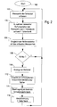
- the FIG. 2 gives a flowchart after which the monitoring system of the combine harvester 10 operates.
- the measured values of the sensors 48, 50, 54, 56 and 58 are detected in step 102 in the computer 46.
- a first database is queried in step 104. All relevant physical characteristics of the combine harvester are entered in this database, in particular information regarding its moving elements.
- the first database records that it has an axial separator 22 (and therefore no straw walkers), including its part number.
- the first database is stored in a memory of the computer 46.
- the data in the first database are determined by the machine design and change at most during a conversion or conversion on the machine.
- the data must be easy to customize. For example, at the start of the monitoring system, they could be made from a machine-specific one File to be read out.
- various possible machine configurations can be taken into account, in which case a corresponding change of the configuration data must be made during a conversion.
- a corresponding new file must be created or a change made to the file, for example by the workshop personnel involved in the conversion.
- the computing device 46 Based on the first database, the computing device 46 has information as to how the combine harvester 10 is configured. On the basis of this information, reference data relevant to the specific configuration of the combine harvester 10 are read out in step 104 from a second database, which is also stored in a memory of the computer device 46.
- Such reference data can be, for example, time-dependent and / or frequency-dependent measured values recorded at a delivery drum 34 with defective bearings, and / or setpoint and threshold values of the sensor signals and / or reference patterns for the combination of specific sensor signals. It can also be stored, for example, temperature curves that occur in defective bearings of the axial separation device 22. Only the reference data that applies to the current configuration of the machine is used.
- the reference data of the axial separation device 22 are selected based on their part number in order to use correct reference data can.
- the trend of results of the previous analysis, assigned to specific assemblies can be stored in the second database.
- the first and second databases can also be integrated with each other; but in many cases it makes more sense to separate them.
- the machine status can be monitored.
- the measured signals or signal patterns can be assigned to a specific component and to a specific damage to the component. More about this assignment is the DE 101 00 522 A and the other publications mentioned in the introduction, the disclosure of which is incorporated by reference into the present documents.
- a query is thus made in step 108 by the computer device 46 as to whether an error has been determined on the basis of this comparison. If this is not the case, step 102 follows again. It can also be recognized in step 108 that an error develops slowly. Based on the results of the signal analysis can be concluded to some extent on the type of damage, z. B. imbalance, striking parts, loose connections.
- step 110 follows, in which the display device 62 indicates to the operator that an error has occurred. It also shows where the error location can be found. The operator can then go to the fault indicated and check the error. In addition, suggestions for a targeted error diagnosis by the operator and suggestions for the repair can be given. For this dialog operation, information from the repair manual and from the spare parts catalog can be made available electronically to the operator or to a service technician involved. This can be done interactively and / or iteratively, ie hints or questions are displayed and the operator indicates whether a particular issue is given or not. In this way, the operator can assist the computer 46 Encircle mistakes.
- the operator can fix it, if possible, or call a repair service. If the operator decides that damage is present but is still acceptable at the moment, he can make a corresponding input and weight the error (eg, light, medium, hard). In this case, the monitoring system will focus on monitoring the symptom of this error and report when the trend goes into a critical area.
- the error eg, light, medium, hard
- the operator or the repair service confirms after the repair has been completed that an error has actually occurred by making a corresponding entry in step 112 into an input device 64, which includes a keyboard, connected to the computer device 46.
- an evaluation of the error can be made, for. Eg using the criteria light, strong, critical, failure o. ⁇ ..
- the automatic weighting of the error can be improved by the monitoring system.
- the operator may enter a corresponding input into the input device 64.
- an input can be made if the computer device 46 has detected no error in step 108, but the operator detected him on his own or a greater damage occurred that was otherwise detectable, especially led to a standstill of the combine 10.
- Information about the type and location of the error is usually entered. In this case, there is the possibility that the computer 46 searches the second database again to determine whether a hitherto unregistered change in the signals or signal patterns can be detected and that these possible changes also make sense to the corresponding component and damage to let.
- Step 112 is followed by step 114, in which a transmission of the measured values and / or the analysis results derived therefrom as well as the inputs of the operator from the computer device 46 a central damage database 66 (in FIG. 1 schematically drawn) takes place.
- the central damage database 66 is located at an arbitrary location, generally spaced from the combine 10. It is preferably operated by the manufacturer of the combine 10.
- the transmission of the measured values can take place wirelessly via a data connection via the telephone network or the Internet in the form of an e-mail or the like. It is also conceivable that the information mentioned initially remain stored in the computer device 46 and transmitted to the central damage database when the combine harvester 10 is in a workshop or is serviced by personnel authorized by the manufacturer.
- step 116 the second database of the combine harvester 10 is updated based on the meanwhile updated damage database 66.
- the transfer takes place analogously to the transfer in step 114, d. H. for example wirelessly over a data connection over the telephone network or in the form of an e-mail or by downloading data from the Internet or during on-site or workshop maintenance by authorized personnel.
- step 102 the updating of the second database can also take place immediately after step 112, so that the new data can be immediately taken into account in a subsequent monitoring.
- step 106 constellations are possible in which the measured values can be assigned to different errors.
- information is preferably stored as to how often the relevant errors in the Past occurred.
- the operator is preferably shown the most frequently encountered error first.
- the possible errors are displayed with the expected probability (derived from the frequency).
- the second database can initially contain only these first reference data. Later, the reference data is accumulated by the method according to the invention.
- the second database contains only the reference data given by the first database. As a result, the memory requirement can be reduced.
- the first database is included in the second database in this embodiment. When the work machine is changed, only the second database is to be updated with the now relevant reference data (i.e., the reference data corresponding to the new state of the machine).
Landscapes
- Physics & Mathematics (AREA)
- General Physics & Mathematics (AREA)
- Life Sciences & Earth Sciences (AREA)
- Environmental Sciences (AREA)
- Management, Administration, Business Operations System, And Electronic Commerce (AREA)
- Testing And Monitoring For Control Systems (AREA)
Claims (8)
- Procédé de surveillance de l'état de machines de travail comprenant les étapes suivantes :fourniture de plusieurs machines de travail,fourniture de capteurs (48, 50, 54, 56, 58) pour détecter l'état de fonctionnement des machines de travail, notamment des bruits et/ou des vibrations généré(e)s par les éléments mobiles de la machine de travail,fourniture d'une première base de données spécifique aux machines de travail avec des données de construction pour chacune des machines de travail,fourniture d'une deuxième base de données spécifique aux machines de travail avec des données de référence spécifiques à l'évaluation pour chacune des machines de travail,acquisition de valeurs mesurées des capteurs (48, 50, 54, 56, 58) d'une machine de travail,analyse des valeurs mesurées des capteurs (48, 50, 54, 56, 58) en ce qui concerne d'éventuels défauts de la machine de travail en utilisant la première et la deuxième bases de données,si l'analyse des valeurs mesurées indique un défaut de la machine de travail, remise d'une information à un opérateur concernant la présence d'une défaut possible et un point de défaut déterminé,fourniture d'un dispositif de saisie (64) qui peut être utilisé pour prendre en charge les saisies d'un opérateur concernant un défaut de la machine de travail réellement découvert par lui,transmission des valeurs mesurées et/ou des résultats d'analyse qui en sont dérivés et des saisies de l'opérateur à une base de données des défauts centrale (66) et actualisation de la base de données des défauts centrale (66) au moyen des données reçues et actualisation de la deuxième base de données en se basant sur la base de données des défauts (66) actualisée.
- Procédé selon la revendication 1, dans lequel, après la saisie d'une exécution d'une réparation, une analyse supplémentaire des valeurs mesurées des capteurs (48, 50, 54, 56, 58) est exécutée.
- Procédé selon la revendication 1 ou 2, dans lequel, après la saisie d'une exécution d'une réparation et/ou d'une modification de la machine de travail, la première base de données spécifique aux machines de travail est actualisée.
- Procédé selon l'une des revendications précédentes, dans lequel la transmission des valeurs mesurées et/ou des résultats d'analyse qui en sont dérivés et des informations de l'opérateur à la base de données des défauts centrale (66) n'a lieu que de temps en temps, par exemple lors d'une maintenance dans un atelier.
- Procédé selon l'une des revendications précédentes, dans lequel la deuxième base de données contient une information concernant la fréquence à laquelle un type de défaut a été constaté dans le passé et, en cas d'apparition d'un défaut pour lequel il existe des valeurs mesurées similaires avec des causes différentes, le défaut qui est indiqué à l'opérateur est de préférence celui qui présente la fréquence la plus élevée.
- Procédé selon l'une des revendications précédentes, dans lequel une évolution du défaut n'est enregistrée dans la base de données des défauts centrale (66) que lorsque le nombre de ses occurrences dépasse une valeur de seuil.
- Système de surveillance pour surveiller l'état de machines de travail, conçu pour exécuter le procédé selon l'une des revendications précédentes.
- Machine de travail, notamment machine de travail agricole, de préférence moissonneuse, équipée d'un système de surveillance selon la revendication 7.
Applications Claiming Priority (2)
| Application Number | Priority Date | Filing Date | Title |
|---|---|---|---|
| DE102004006848 | 2004-02-12 | ||
| DE102004006848A DE102004006848A1 (de) | 2004-02-12 | 2004-02-12 | Verfahren und Überwachungssystem zur Überwachung des Zustands von Arbeitsmaschinen |
Publications (2)
| Publication Number | Publication Date |
|---|---|
| EP1564688A1 EP1564688A1 (fr) | 2005-08-17 |
| EP1564688B1 true EP1564688B1 (fr) | 2011-03-30 |
Family
ID=34684017
Family Applications (1)
| Application Number | Title | Priority Date | Filing Date |
|---|---|---|---|
| EP05100822A Expired - Lifetime EP1564688B1 (fr) | 2004-02-12 | 2005-02-07 | Dispositif et procédé de surveillance pour surveiller l'état d'une machine de travail |
Country Status (3)
| Country | Link |
|---|---|
| US (1) | US20060020402A1 (fr) |
| EP (1) | EP1564688B1 (fr) |
| DE (2) | DE102004006848A1 (fr) |
Cited By (1)
| Publication number | Priority date | Publication date | Assignee | Title |
|---|---|---|---|---|
| US12033439B2 (en) | 2021-05-14 | 2024-07-09 | Deere & Company | Fault detection and mitigation on an agricultural machine |
Families Citing this family (42)
| Publication number | Priority date | Publication date | Assignee | Title |
|---|---|---|---|---|
| DE102005023256A1 (de) * | 2005-05-20 | 2006-11-23 | Deere & Company, Moline | Überwachungseinrichtung und ein Verfahren zur Überwachung der Funktion der Komponenten einer landwirtschaftlichen Arbeitsmaschine |
| JP4717579B2 (ja) * | 2005-09-30 | 2011-07-06 | 株式会社小松製作所 | 作業機械のメンテナンス作業管理システム |
| EP1791094A1 (fr) * | 2005-11-10 | 2007-05-30 | Siemens Aktiengesellschaft | Automatic maintenance system for an technical installation |
| DE102006004717A1 (de) * | 2006-01-31 | 2007-08-16 | Claas Selbstfahrende Erntemaschinen Gmbh | Anzeigeneinheit antriebsspezifischer Zustandsinformationen auf einem landwirtschaftlich nutzbaren Motorfahrzeug |
| DE102006030970A1 (de) | 2006-07-03 | 2008-01-17 | Claas Selbstfahrende Erntemaschinen Gmbh | Methode zur Datenkonfiguration und Bereitstellung insbesondere für landwirtschaftliche Arbeitsmaschinen |
| DE102008021362B3 (de) | 2008-04-29 | 2009-07-02 | Siemens Aktiengesellschaft | Verfahren und Vorrichtung zum Erkennen eines Zustandes einer zu untersuchenden geräuscherzeugenden Maschine |
| DE102009046821B4 (de) * | 2009-11-18 | 2015-12-24 | Deere & Company | Anordnung zur selbsttätigen Erkennung des Übersetzungsverhältnisses eines Antriebsstrangs für ein Arbeitsorgan und/oder der Anzahl an aktiven beweglichen Elementen eines Arbeitsorgans einer landwirtschaftlichen Erntemaschine |
| ES2386180B1 (es) * | 2010-05-05 | 2013-07-01 | Universidad De Valladolid | Metodo y dispositivo de deteccion de averias en maquinaria de trabajo en campo mediante sonido |
| US20120101863A1 (en) * | 2010-10-22 | 2012-04-26 | Byron Edwin Truax | Machine-management system |
| US20120253743A1 (en) * | 2010-12-30 | 2012-10-04 | Agco Corporation | Real-Time Determination of Machine Performance for Fleet Management |
| US20140160152A1 (en) * | 2012-12-07 | 2014-06-12 | General Electric Company | Methods and systems for integrated plot training |
| US9761027B2 (en) | 2012-12-07 | 2017-09-12 | General Electric Company | Methods and systems for integrated plot training |
| US9826682B2 (en) * | 2013-03-18 | 2017-11-28 | Deere & Company | Operating state detection system for work machine with fusion considering sensor value reliability |
| RU2658981C2 (ru) * | 2013-06-18 | 2018-06-26 | Дир Энд Компани | Система выявления рабочего состояния для рабочей машины с объединением, учитывающим достоверность значений датчиков |
| BR112015008318A2 (pt) | 2013-09-23 | 2017-07-04 | Farmobile Llc | dispositivo de retransmissão, e, sistemas de troca de dados de agricultura e de servidor |
| CN103558837B (zh) * | 2013-10-10 | 2015-11-18 | 浙江大学 | 一种空分设备工况波动的修复方法 |
| US20150212025A1 (en) * | 2014-01-30 | 2015-07-30 | Caterpillar Inc. | Harness Diagnostics System for a Machine |
| CN104122865B (zh) * | 2014-07-17 | 2017-04-12 | 江苏大学 | 农机故障分析维修方法和系统 |
| US9901031B2 (en) * | 2014-09-24 | 2018-02-27 | Deere & Company | Automatic tuning of an intelligent combine |
| US9934538B2 (en) | 2014-09-24 | 2018-04-03 | Deere & Company | Recalling crop-specific performance targets for controlling a mobile machine |
| DE102014219586A1 (de) | 2014-09-26 | 2016-03-31 | Deere & Company | Landwirtschaftliche Erntemaschine mit einem austauschbaren Erntegutbearbeitungselement |
| JP6392101B2 (ja) * | 2014-12-05 | 2018-09-19 | 日立建機株式会社 | 建設機械の管理システム |
| DE102015207895A1 (de) * | 2015-04-29 | 2016-11-03 | Continental Automotive Gmbh | Verfahren zur Überwachung eines elektronischen Steuergeräts und Steuergerät für ein Kraftfahrzeug |
| ITUB20155784A1 (it) * | 2015-11-20 | 2017-05-20 | Cnh Ind Italia Spa | Metodo e sistema per la diagnosi predittiva |
| DE102016213584A1 (de) | 2016-07-25 | 2018-01-25 | Deere & Company | Verfahren, tragbares Gerät und Kombination aus einer mobilen Arbeitsmaschine und einem tragbaren Gerät zur Unterstützung des Auffindens einer zu Fehlerbehebungs -, Störungsbeseitigungs- oder Wartungsarbeiten aufzusuchenden Position an einer mobilen Arbeitsmaschine oder einem damit gekoppelten Gerät |
| US10773665B2 (en) * | 2018-10-16 | 2020-09-15 | Cnh Industrial America Llc | System and method for detecting a damage condition associated with an agricultural machine |
| US11475717B2 (en) * | 2019-01-11 | 2022-10-18 | Cnh Industrial America Llc | System and method for detecting worn or damaged components of an agricultural machine based on acoustic data |
| DE102019108278A1 (de) * | 2019-03-29 | 2020-10-01 | Liebherr-Components Biberach Gmbh | Vorrichtung zum Ermitteln des Ist-Zustands und/oder der Restlebensdauer einer Baumaschine |
| DE102019112569A1 (de) * | 2019-05-14 | 2020-11-19 | Claas Selbstfahrende Erntemaschinen Gmbh | Verfahren zur Ermittlung einer Fehlerursache bei einer landwirtschaftlichen Arbeitsmaschine |
| US11212963B2 (en) * | 2019-05-16 | 2022-01-04 | Cnh Industrial America Llc | Failsafe mode for articulating harvesting header |
| DE102019120217A1 (de) * | 2019-07-26 | 2021-01-28 | Pöttinger Landtechnik Gmbh | Landwirtschaftliche Maschine |
| DE102019220530A1 (de) * | 2019-12-23 | 2021-06-24 | Robert Bosch Gesellschaft mit beschränkter Haftung | Verfahren und Vorrichtung zur Ermittlung einer Bauteileigenschaft während eines Fertigungsprozesses |
| US12016257B2 (en) | 2020-02-19 | 2024-06-25 | Sabanto, Inc. | Methods for detecting and clearing debris from planter gauge wheels, closing wheels and seed tubes |
| DE102020202479A1 (de) | 2020-02-26 | 2021-08-26 | Man Energy Solutions Se | Verfahren und Vorrichtung zum Extrahieren von Sequenzmustern aus erfassten Zustandsdaten zur Zustandsüberwachung einer Maschine |
| US12461083B2 (en) | 2020-08-03 | 2025-11-04 | Sabanto, Inc. | Methods for improved agricultural procedures |
| US11776329B2 (en) | 2020-09-15 | 2023-10-03 | Deere & Company | Sound analysis to identify a damaged component in a work machine |
| EP4062744B1 (fr) * | 2021-03-26 | 2025-05-28 | CNH Industrial Belgium N.V. | Surveillance des vibrations dans machines de récolte agricoles |
| DE102021120491A1 (de) | 2021-05-06 | 2022-11-10 | Liebherr-Components Biberach Gmbh | Vorrichtung zum Bestimmen des Ist-Zustands und/oder der Restlebensdauer von Strukturbauteilen einer Arbeitsmaschine |
| DE102022205289A1 (de) | 2022-05-25 | 2023-11-30 | Robert Bosch Gesellschaft mit beschränkter Haftung | Hydraulikgerät mit Statusanzeige |
| DE102022132216A1 (de) * | 2022-12-05 | 2024-06-06 | Lenze Se | Verfahren zur Überwachung einer technischen Einrichtung |
| US12520758B2 (en) | 2024-05-23 | 2026-01-13 | Deere & Company | Controlling an agricultural harvester based upon material other than grain (MOG) content characteristics |
| CN120240137B (zh) * | 2025-05-30 | 2025-11-28 | 山东常美机械制造有限公司 | 一种基于强化学习的玉米收割机节能调控方法、系统 |
Family Cites Families (24)
| Publication number | Priority date | Publication date | Assignee | Title |
|---|---|---|---|---|
| US4985857A (en) * | 1988-08-19 | 1991-01-15 | General Motors Corporation | Method and apparatus for diagnosing machines |
| JPH0692914B2 (ja) * | 1989-04-14 | 1994-11-16 | 株式会社日立製作所 | 機器/設備の状態診断システム |
| DE4127395A1 (de) * | 1991-08-19 | 1993-02-25 | Siemens Ag | Verfahren und vorrichtung zum erkennen und orten von veraenderungen an einem bauteil einer turbine |
| GB2271004A (en) * | 1992-09-28 | 1994-03-30 | Ford Motor Co | Expert system for diagnosing machines. |
| DE4406723B4 (de) * | 1993-02-27 | 2005-02-03 | Dr. Boetius + Partner Informationssysteme Gmbh | Verfahren zur Überwachung des Betriebszustands einer Maschine oder Anlage |
| DE19545008C5 (de) * | 1995-12-02 | 2004-07-22 | Reilhofer Kg | Verfahren zur Überwachung von periodisch arbeitenden Maschinen |
| DE19711338B4 (de) * | 1997-03-18 | 2005-09-29 | Bayerische Motoren Werke Ag | Verfahren zum Signalisieren einer Service-Maßnahme |
| DE19725028A1 (de) * | 1997-06-13 | 1998-12-17 | Claas Selbstfahr Erntemasch | Sensor für Erntemaschinen |
| DE19808197C2 (de) * | 1998-02-27 | 2001-08-09 | Mtu Aero Engines Gmbh | System und Verfahren zur Diagnose von Triebwerkszuständen |
| GB9811024D0 (en) * | 1998-05-22 | 1998-07-22 | Ford New Holland Nv | Harvester with crop flow rate sensor |
| DE19902326C2 (de) * | 1999-01-21 | 2003-05-08 | Medav Digitale Signalverarbeit | Verfahren zur Schadensfrüherkennung von rotierenden Maschinen |
| US6505145B1 (en) * | 1999-02-22 | 2003-01-07 | Northeast Equipment Inc. | Apparatus and method for monitoring and maintaining plant equipment |
| US6553336B1 (en) * | 1999-06-25 | 2003-04-22 | Telemonitor, Inc. | Smart remote monitoring system and method |
| EP1111550B1 (fr) * | 1999-12-23 | 2003-08-27 | Abb Ab | Méthode et système pour surveiller le fonctionnement d'une machine isolée |
| DE10024211B4 (de) * | 2000-05-17 | 2010-05-12 | Volkswagen Ag | Diagnoseverfahren für den Zustand eines Kraftfahrzeuges |
| US20020007237A1 (en) * | 2000-06-14 | 2002-01-17 | Phung Tam A. | Method and system for the diagnosis of vehicles |
| DE10064754A1 (de) * | 2000-12-22 | 2002-07-04 | Daimler Chrysler Ag | Verfahren und Anordnung zur Bestimmung eines Geräuschsignals einer Geräuschquelle |
| DE10100522B4 (de) * | 2001-01-08 | 2013-03-28 | Deere & Company | Überwachungseinrichtung zur Überwachung der Funktion einer Arbeitsmaschine |
| DE10100444A1 (de) * | 2001-01-08 | 2002-07-18 | Dieter Frey | Vorrichtung um Schwingungen und die dazu gehörenden Geräusche technischer Einrichtungen zu erfassen und auszuwerten |
| US20020116107A1 (en) * | 2001-02-07 | 2002-08-22 | Deere & Company | Method of monitoring equipment of an agricultural machine |
| US7089154B2 (en) * | 2001-08-09 | 2006-08-08 | Rovsing Dynamics A/S | Automatic machinery fault diagnostic method and apparatus |
| US20030236601A1 (en) * | 2002-03-18 | 2003-12-25 | Club Car, Inc. | Control and diagnostic system for vehicles |
| US6745151B2 (en) * | 2002-05-16 | 2004-06-01 | Ford Global Technologies, Llc | Remote diagnostics and prognostics methods for complex systems |
| US7689394B2 (en) * | 2003-08-26 | 2010-03-30 | Siemens Industry, Inc. | System and method for remotely analyzing machine performance |
-
2004
- 2004-02-12 DE DE102004006848A patent/DE102004006848A1/de not_active Ceased
-
2005
- 2005-02-07 EP EP05100822A patent/EP1564688B1/fr not_active Expired - Lifetime
- 2005-02-07 DE DE502005011181T patent/DE502005011181D1/de not_active Expired - Lifetime
- 2005-08-05 US US11/198,585 patent/US20060020402A1/en not_active Abandoned
Cited By (1)
| Publication number | Priority date | Publication date | Assignee | Title |
|---|---|---|---|---|
| US12033439B2 (en) | 2021-05-14 | 2024-07-09 | Deere & Company | Fault detection and mitigation on an agricultural machine |
Also Published As
| Publication number | Publication date |
|---|---|
| DE102004006848A1 (de) | 2005-09-01 |
| EP1564688A1 (fr) | 2005-08-17 |
| US20060020402A1 (en) | 2006-01-26 |
| DE502005011181D1 (de) | 2011-05-12 |
Similar Documents
| Publication | Publication Date | Title |
|---|---|---|
| EP1564688B1 (fr) | Dispositif et procédé de surveillance pour surveiller l'état d'une machine de travail | |
| EP1724730B1 (fr) | Dispositif et procédé de surveillance de la fonction des constituantes d'une machine de travail agricole | |
| DE10100522B4 (de) | Überwachungseinrichtung zur Überwachung der Funktion einer Arbeitsmaschine | |
| EP2730906B1 (fr) | Dispositif et procédé de surveillance de l'état d'un palier à roulement | |
| EP1839478B1 (fr) | Unité de détection de vibrations corporelles | |
| WO2003058561A2 (fr) | Systeme de surveillance destine a un parc de machines agricoles | |
| EP2132974B1 (fr) | Moissonneuse agricole | |
| DE10204076B4 (de) | Überwachungseinrichtung für eine landwirtschaftliche Maschine | |
| DE102017211043B3 (de) | Verfahren zur Analyse und/oder zur zumindest teilweisen Kompensation von Lenkraddrehschwingungen | |
| EP2728523A1 (fr) | Système d'assistance pour l'optimisation du fonctionnement d'un véhicule | |
| DE10148214A1 (de) | Verfahren zur Bereitstellung eines Wartungsalgorithmus | |
| EP2083338A2 (fr) | Procödé et dispositif de surveillance d'une machine | |
| DE102015225144A1 (de) | System und Verfahren zur Diagnose von zumindest einer wartungsbedürftigen Komponente eines Geräts und/oder Anlage | |
| DE60011142T2 (de) | Vorrichtung und verfahren für leistungs- und fehlerdatenanalyse | |
| EP1332658A1 (fr) | Machine avec commande portable | |
| DE102021106067A1 (de) | Echtzeit-erkennung von riemenausfällen | |
| DE102021203806A1 (de) | Verfahren zur Überwachung des Betriebs eines Ventilators, Vorrichtung und Ventilator | |
| EP1900272B1 (fr) | Machine de travail agricole | |
| DE102018131748B4 (de) | Verfahren und Überwachungssystem zur akustischen Überwachung einer mobilen Landmaschine | |
| DE102008019463A1 (de) | Verfahren zum Vorhersagen von Ausfallereignissen | |
| EP4256939B1 (fr) | Engin d'abattage-façonnage permettant de traiter les produits de la récolte et procédés de détermination des propriétés des produits de la récolte | |
| EP2184658A2 (fr) | Dispositif et procédé de collecte et de préparation de données d'au moins une presse | |
| DE102024112075A1 (de) | Landwirtschaftliche Arbeitsmaschine sowie Verfahren und Vorrichtung zum Überwachen des Schmiermittelsystems einer solchen Maschine | |
| DE102023121771A1 (de) | Verfahren zum Bestimmen eines Verschleißzustands einer landwirtschaftlichen Ballenpresse | |
| EP4049098A1 (fr) | Système et procédé de détection et d'évaluation de données de mesure, de fonctionnement et/ou de production pertinentes en termes d'entretien et de maintenance |
Legal Events
| Date | Code | Title | Description |
|---|---|---|---|
| PUAI | Public reference made under article 153(3) epc to a published international application that has entered the european phase |
Free format text: ORIGINAL CODE: 0009012 |
|
| AK | Designated contracting states |
Kind code of ref document: A1 Designated state(s): AT BE BG CH CY CZ DE DK EE ES FI FR GB GR HU IE IS IT LI LT LU MC NL PL PT RO SE SI SK TR |
|
| AX | Request for extension of the european patent |
Extension state: AL BA HR LV MK YU |
|
| 17P | Request for examination filed |
Effective date: 20060217 |
|
| AKX | Designation fees paid |
Designated state(s): BE DE FI IT |
|
| GRAP | Despatch of communication of intention to grant a patent |
Free format text: ORIGINAL CODE: EPIDOSNIGR1 |
|
| GRAS | Grant fee paid |
Free format text: ORIGINAL CODE: EPIDOSNIGR3 |
|
| GRAA | (expected) grant |
Free format text: ORIGINAL CODE: 0009210 |
|
| AK | Designated contracting states |
Kind code of ref document: B1 Designated state(s): BE DE FI IT |
|
| REF | Corresponds to: |
Ref document number: 502005011181 Country of ref document: DE Date of ref document: 20110512 Kind code of ref document: P |
|
| REG | Reference to a national code |
Ref country code: DE Ref legal event code: R096 Ref document number: 502005011181 Country of ref document: DE Effective date: 20110512 |
|
| PG25 | Lapsed in a contracting state [announced via postgrant information from national office to epo] |
Ref country code: FI Free format text: LAPSE BECAUSE OF FAILURE TO SUBMIT A TRANSLATION OF THE DESCRIPTION OR TO PAY THE FEE WITHIN THE PRESCRIBED TIME-LIMIT Effective date: 20110330 |
|
| PLBE | No opposition filed within time limit |
Free format text: ORIGINAL CODE: 0009261 |
|
| STAA | Information on the status of an ep patent application or granted ep patent |
Free format text: STATUS: NO OPPOSITION FILED WITHIN TIME LIMIT |
|
| 26N | No opposition filed |
Effective date: 20120102 |
|
| REG | Reference to a national code |
Ref country code: DE Ref legal event code: R097 Ref document number: 502005011181 Country of ref document: DE Effective date: 20120102 |
|
| PGFP | Annual fee paid to national office [announced via postgrant information from national office to epo] |
Ref country code: IT Payment date: 20190222 Year of fee payment: 15 |
|
| PGFP | Annual fee paid to national office [announced via postgrant information from national office to epo] |
Ref country code: BE Payment date: 20190227 Year of fee payment: 15 |
|
| REG | Reference to a national code |
Ref country code: BE Ref legal event code: MM Effective date: 20200229 |
|
| PG25 | Lapsed in a contracting state [announced via postgrant information from national office to epo] |
Ref country code: BE Free format text: LAPSE BECAUSE OF NON-PAYMENT OF DUE FEES Effective date: 20200229 |
|
| PG25 | Lapsed in a contracting state [announced via postgrant information from national office to epo] |
Ref country code: IT Free format text: LAPSE BECAUSE OF NON-PAYMENT OF DUE FEES Effective date: 20200207 |
|
| PGFP | Annual fee paid to national office [announced via postgrant information from national office to epo] |
Ref country code: DE Payment date: 20240119 Year of fee payment: 20 |
|
| REG | Reference to a national code |
Ref country code: DE Ref legal event code: R071 Ref document number: 502005011181 Country of ref document: DE |