EP1564688B1 - Monitoring system and device for monitoring the condition of a working machine - Google Patents
Monitoring system and device for monitoring the condition of a working machine Download PDFInfo
- Publication number
- EP1564688B1 EP1564688B1 EP05100822A EP05100822A EP1564688B1 EP 1564688 B1 EP1564688 B1 EP 1564688B1 EP 05100822 A EP05100822 A EP 05100822A EP 05100822 A EP05100822 A EP 05100822A EP 1564688 B1 EP1564688 B1 EP 1564688B1
- Authority
- EP
- European Patent Office
- Prior art keywords
- database
- working
- machine
- fault
- operator
- Prior art date
- Legal status (The legal status is an assumption and is not a legal conclusion. Google has not performed a legal analysis and makes no representation as to the accuracy of the status listed.)
- Expired - Lifetime
Links
Images

Classifications
-
- G—PHYSICS
- G07—CHECKING-DEVICES
- G07C—TIME OR ATTENDANCE REGISTERS; REGISTERING OR INDICATING THE WORKING OF MACHINES; GENERATING RANDOM NUMBERS; VOTING OR LOTTERY APPARATUS; ARRANGEMENTS, SYSTEMS OR APPARATUS FOR CHECKING NOT PROVIDED FOR ELSEWHERE
- G07C3/00—Registering or indicating the condition or the working of machines or other apparatus, other than vehicles
-
- A—HUMAN NECESSITIES
- A01—AGRICULTURE; FORESTRY; ANIMAL HUSBANDRY; HUNTING; TRAPPING; FISHING
- A01D—HARVESTING; MOWING
- A01D41/00—Combines, i.e. harvesters or mowers combined with threshing devices
- A01D41/12—Details of combines
- A01D41/127—Control or measuring arrangements specially adapted for combines
-
- G—PHYSICS
- G01—MEASURING; TESTING
- G01H—MEASUREMENT OF MECHANICAL VIBRATIONS OR ULTRASONIC, SONIC OR INFRASONIC WAVES
- G01H1/00—Measuring characteristics of vibrations in solids by using direct conduction to the detector
-
- G—PHYSICS
- G01—MEASURING; TESTING
- G01H—MEASUREMENT OF MECHANICAL VIBRATIONS OR ULTRASONIC, SONIC OR INFRASONIC WAVES
- G01H1/00—Measuring characteristics of vibrations in solids by using direct conduction to the detector
- G01H1/003—Measuring characteristics of vibrations in solids by using direct conduction to the detector of rotating machines
-
- G—PHYSICS
- G07—CHECKING-DEVICES
- G07C—TIME OR ATTENDANCE REGISTERS; REGISTERING OR INDICATING THE WORKING OF MACHINES; GENERATING RANDOM NUMBERS; VOTING OR LOTTERY APPARATUS; ARRANGEMENTS, SYSTEMS OR APPARATUS FOR CHECKING NOT PROVIDED FOR ELSEWHERE
- G07C5/00—Registering or indicating the working of vehicles
- G07C5/008—Registering or indicating the working of vehicles communicating information to a remotely located station
-
- G—PHYSICS
- G07—CHECKING-DEVICES
- G07C—TIME OR ATTENDANCE REGISTERS; REGISTERING OR INDICATING THE WORKING OF MACHINES; GENERATING RANDOM NUMBERS; VOTING OR LOTTERY APPARATUS; ARRANGEMENTS, SYSTEMS OR APPARATUS FOR CHECKING NOT PROVIDED FOR ELSEWHERE
- G07C5/00—Registering or indicating the working of vehicles
- G07C5/08—Registering or indicating performance data other than driving, working, idle, or waiting time, with or without registering driving, working, idle or waiting time
- G07C5/0841—Registering performance data
- G07C5/085—Registering performance data using electronic data carriers
Definitions
- the invention relates to a method and a monitoring system for monitoring the condition of working machines.
- a monitoring device for a work machine includes one or more sensors that detect noise generated by moving elements of the work machine.
- the signals from the sensors are compared with comparison values to find out if the work machine is operating correctly or if there is a fault that gives rise to a repair.
- the comparison values come from fault-free machines, are recorded on the examined machine or correspond to machines with a known error.
- the DE 199 38 722 A describes a method for analyzing rolling bearings in machines.
- a signal is recorded, which is generated by the rolling motion of the rolling bearing.
- the amplitude of the signal is evaluated to determine the presence and, if necessary, depth of damage in a rolling bearing raceway.
- the analysis is based on a dynamic model of the rolling bearing in the machine. It uses a database that contains data regarding specific properties of the warehouse. When capturing a machine not yet registered in the database, the properties of the warehouse are recorded, partly by measurements. In addition, the sounds of the camp are detected. After a successful measurement, ie when there is damage, all machine and storage data flow back into the central database. In this way, the database is constantly being improved.
- An analysis of damage patterns is also in the DE 102 20 124 A disclosed. There, the measured data are first assigned by comparison with stored patterns of a class and processed by means of a neural network. There are several damage classes stored in this network. If a new damage can not be clearly assigned to the existing classes, a new class is opened.
- the DE 101 45 571 A describes a system for monitoring construction machinery. Reference is made to known methods by which data on the operating state of a defective construction machine, including measured fault data and a visual inspection-based error code, are sent wirelessly to the management department of a manufacturer. There, an examination of the data and, if necessary, an instigation of a repair. The criteria for damage are fixed.
- a method and system for diagnosing vehicles is described.
- Several vehicles are equipped with sensors to record their operating status.
- a local server includes a database of reference data that is compared with data provided by the sensors of the vehicles to detect possible errors of the vehicle. If the comparison gives an indication of a possible error, information regarding the presence of a possible error is given to an operator. The latter can input information about an actually found error into an input device. This information is sent to a central claims database, which is updated based on the received data and, in turn, passes updated data to the local server databases.
- the system described is suitable only for a single type of vehicles.
- the object underlying the invention is to provide a method and a monitoring system for monitoring the condition of working machines, which is applicable to relatively complicated machines, in which the vibration behavior and other effects such as temperature changes (for example in bearings, clutches) in Connection with component defects, can not be described by simple theoretical models and just as easy to analyze.
- a method and monitoring system for monitoring the condition of a plurality of work machines is proposed.
- the work machines are equipped with sensors that detect their operating condition and / or noises or vibrations generated by moving elements of the work machine.
- a first database is provided which contains design data of the machine, ie information about the respective physical structure of the machine.
- a second database containing reference data.
- This database may, for example, contain information about the noises or vibrations occurring in certain cases of damage and / or other typical measured value profiles in the event of damage. It is possible to consider different parameters such as temperature, speeds, power, etc.
- the combination of different metrics may be a better indication of an error than a single metric, or may be useful for better localization of an error.
- the signals from the sensors are analyzed using the first database and the second database.
- the first database On the basis of the first database, it is possible to see which signal curves are suitable as error indicators in the given configuration of the machine.
- the measured signal profiles are only compared with the possible error signal profiles, ie only the reference data selected on the basis of the first database from the second database are used for a comparison.
- the second database On the basis of the second database, it can be recognized whether a signal profile is critical or not.
- an operator of the work machine or a responsible person is informed by being signaled to him the existence of a possible error and the determined fault location.
- the person in charge can be called in via a wireless or wired connection, in particular a telephone connection, email or the like, in order to assess the error. This procedure is particularly useful when the machine is working unmanned.
- the operator can now inspect the defect and, if necessary, repair the damage or consult a repair service. If the operator actually detects the diagnosed error, he can make a corresponding input. Otherwise, he can enter that no error has been found, or that a mistake has been found elsewhere.
- the measured values before the occurrence of the fault diagnosis and / or the analysis results derived therefrom are transmitted to a central damage database, which is maintained and operated by the manufacturer of the working machines, for example.
- a central loss database which is maintained and operated by the manufacturer of the working machines, for example.
- successive new measured values which have led to errors, and the information of the operator to the errors a.
- the central loss database will be updated gradually. It also serves to update the second damage database for the machine.
- the sensors allow a check whether a performed repair was successful. It therefore makes sense, after carrying out a repair, to subject the measured values of the sensors again to an analysis for errors of the machine.
- the first database is to be changed if the work machine is changed by installing and / or removing parts.
- the invention is particularly suitable for monitoring agricultural machines, in particular harvesters.
- FIG. 1 shows an agricultural combine harvester 10 with a chassis 12 and from this downwardly extending ground wheels 14, on the example of the invention explains becomes.
- a crop gathering device 16 in the form of a header is used to pick up crop material and feed it to an inclined conveyor 18.
- the crop is fed by the feeder 18 of a guide drum 20.
- the baffle 20 forwards the crop upward through an inlet transition region to an axial separation device 22.
- the Axialtrennvoriques 22 threshes and separates the harvested good. Grain and chaff fall through grates at the bottom of the axial separator 22 into a cleaning system 26.
- the cleaning system 26 removes the chaff and feeds the clean grain to a grain elevator (not shown).
- the grain elevator deposits the clean grain in a grain tank 28.
- the clean grain in the grain tank 28 may be unloaded by a discharge auger 30 into a trailer or truck.
- Threshed straw freed of grain is fed out of the axial separation device 22 through an outlet 32 to a discharge drum 34.
- the axial separation device 22 comprises a cylindrical rotor housing 38 and a rotor 39 arranged in the rotor housing 38.
- the delivery drum 34 ejects the straw at the rear end of the combine 10.
- the operation of the combine harvester 10 takes place from a driver's cab 36.
- a computer device 46 is arranged, which is connected to various sensors.
- a sensor 48 is mounted on the axial separator 22 and senses vibrations of the rotor housing 38. Attached to the chassis 12 near the dispensing drum 34 is a sensor 50 which senses vibrations of the chassis 12 carrying it from the dispenser drum 34. In the vicinity of a blower or fan 52 of the cleaning device on the chassis 12, a sensor 54 is arranged. A speed sensor 58 detects the rotational speed of the rotor 39 inductively by a permanent magnet 60 mounted on the rotor 39. A sensor 56 is mounted on the chassis 12 above the cleaning system 26.
- the sensors 48, 50, 54 and 56 are per se known sensors which are arranged to generate signals which contain information about the sound waves picked up by the sensors 48, 50, 54 and 56. In particular, these may be acoustic or acceleration sensors.
- the sensor 48 primarily (mainly) provides information about the movement of the rotor housing 38 and thus vibrations caused by the rotating rotor 39.
- the sensor 50 primarily provides information about vibrations of the chassis 12 caused by the delivery drum 34.
- the sensor 54 primarily provides information about the vibrations caused by the fan 52.
- the sensor 56 provides information about the vibrations of the chassis caused by all the moving elements of the combine 10.
- the sensors 48, 50, 54, 56 and 58 are electrically (or optically) connected to the computer 46, preferably via a bus line.
- the computer 46 digitizes the analog signals of the sensors, evaluates them and gives the operator in the driver's cab 36 on a display device 62 an error message when the error of the combine harvester 10 can be seen from the signals.
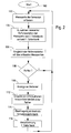
- the FIG. 2 gives a flowchart after which the monitoring system of the combine harvester 10 operates.
- the measured values of the sensors 48, 50, 54, 56 and 58 are detected in step 102 in the computer 46.
- a first database is queried in step 104. All relevant physical characteristics of the combine harvester are entered in this database, in particular information regarding its moving elements.
- the first database records that it has an axial separator 22 (and therefore no straw walkers), including its part number.
- the first database is stored in a memory of the computer 46.
- the data in the first database are determined by the machine design and change at most during a conversion or conversion on the machine.
- the data must be easy to customize. For example, at the start of the monitoring system, they could be made from a machine-specific one File to be read out.
- various possible machine configurations can be taken into account, in which case a corresponding change of the configuration data must be made during a conversion.
- a corresponding new file must be created or a change made to the file, for example by the workshop personnel involved in the conversion.
- the computing device 46 Based on the first database, the computing device 46 has information as to how the combine harvester 10 is configured. On the basis of this information, reference data relevant to the specific configuration of the combine harvester 10 are read out in step 104 from a second database, which is also stored in a memory of the computer device 46.
- Such reference data can be, for example, time-dependent and / or frequency-dependent measured values recorded at a delivery drum 34 with defective bearings, and / or setpoint and threshold values of the sensor signals and / or reference patterns for the combination of specific sensor signals. It can also be stored, for example, temperature curves that occur in defective bearings of the axial separation device 22. Only the reference data that applies to the current configuration of the machine is used.
- the reference data of the axial separation device 22 are selected based on their part number in order to use correct reference data can.
- the trend of results of the previous analysis, assigned to specific assemblies can be stored in the second database.
- the first and second databases can also be integrated with each other; but in many cases it makes more sense to separate them.
- the machine status can be monitored.
- the measured signals or signal patterns can be assigned to a specific component and to a specific damage to the component. More about this assignment is the DE 101 00 522 A and the other publications mentioned in the introduction, the disclosure of which is incorporated by reference into the present documents.
- a query is thus made in step 108 by the computer device 46 as to whether an error has been determined on the basis of this comparison. If this is not the case, step 102 follows again. It can also be recognized in step 108 that an error develops slowly. Based on the results of the signal analysis can be concluded to some extent on the type of damage, z. B. imbalance, striking parts, loose connections.
- step 110 follows, in which the display device 62 indicates to the operator that an error has occurred. It also shows where the error location can be found. The operator can then go to the fault indicated and check the error. In addition, suggestions for a targeted error diagnosis by the operator and suggestions for the repair can be given. For this dialog operation, information from the repair manual and from the spare parts catalog can be made available electronically to the operator or to a service technician involved. This can be done interactively and / or iteratively, ie hints or questions are displayed and the operator indicates whether a particular issue is given or not. In this way, the operator can assist the computer 46 Encircle mistakes.
- the operator can fix it, if possible, or call a repair service. If the operator decides that damage is present but is still acceptable at the moment, he can make a corresponding input and weight the error (eg, light, medium, hard). In this case, the monitoring system will focus on monitoring the symptom of this error and report when the trend goes into a critical area.
- the error eg, light, medium, hard
- the operator or the repair service confirms after the repair has been completed that an error has actually occurred by making a corresponding entry in step 112 into an input device 64, which includes a keyboard, connected to the computer device 46.
- an evaluation of the error can be made, for. Eg using the criteria light, strong, critical, failure o. ⁇ ..
- the automatic weighting of the error can be improved by the monitoring system.
- the operator may enter a corresponding input into the input device 64.
- an input can be made if the computer device 46 has detected no error in step 108, but the operator detected him on his own or a greater damage occurred that was otherwise detectable, especially led to a standstill of the combine 10.
- Information about the type and location of the error is usually entered. In this case, there is the possibility that the computer 46 searches the second database again to determine whether a hitherto unregistered change in the signals or signal patterns can be detected and that these possible changes also make sense to the corresponding component and damage to let.
- Step 112 is followed by step 114, in which a transmission of the measured values and / or the analysis results derived therefrom as well as the inputs of the operator from the computer device 46 a central damage database 66 (in FIG. 1 schematically drawn) takes place.
- the central damage database 66 is located at an arbitrary location, generally spaced from the combine 10. It is preferably operated by the manufacturer of the combine 10.
- the transmission of the measured values can take place wirelessly via a data connection via the telephone network or the Internet in the form of an e-mail or the like. It is also conceivable that the information mentioned initially remain stored in the computer device 46 and transmitted to the central damage database when the combine harvester 10 is in a workshop or is serviced by personnel authorized by the manufacturer.
- step 116 the second database of the combine harvester 10 is updated based on the meanwhile updated damage database 66.
- the transfer takes place analogously to the transfer in step 114, d. H. for example wirelessly over a data connection over the telephone network or in the form of an e-mail or by downloading data from the Internet or during on-site or workshop maintenance by authorized personnel.
- step 102 the updating of the second database can also take place immediately after step 112, so that the new data can be immediately taken into account in a subsequent monitoring.
- step 106 constellations are possible in which the measured values can be assigned to different errors.
- information is preferably stored as to how often the relevant errors in the Past occurred.
- the operator is preferably shown the most frequently encountered error first.
- the possible errors are displayed with the expected probability (derived from the frequency).
- the second database can initially contain only these first reference data. Later, the reference data is accumulated by the method according to the invention.
- the second database contains only the reference data given by the first database. As a result, the memory requirement can be reduced.
- the first database is included in the second database in this embodiment. When the work machine is changed, only the second database is to be updated with the now relevant reference data (i.e., the reference data corresponding to the new state of the machine).
Landscapes
- Physics & Mathematics (AREA)
- General Physics & Mathematics (AREA)
- Life Sciences & Earth Sciences (AREA)
- Environmental Sciences (AREA)
- Management, Administration, Business Operations System, And Electronic Commerce (AREA)
- Testing And Monitoring For Control Systems (AREA)
Description
Die Erfindung betrifft ein Verfahren und ein Überwachungssystem zur Überwachung des Zustands von Arbeitsmaschinen.The invention relates to a method and a monitoring system for monitoring the condition of working machines.
In der
Die
In der
Eine Analyse von Schadensmustern wird auch in der
Die
In der
Es ist somit eine Reihe von Systemen zur automatischen Analyse von Schäden an Maschinen bekannt, die auf einer Analyse aufgenommener Vibrationen und anderer Betriebsdaten der Maschine beruhen. Ein Problem bei der automatischen Analyse von Schäden ist die Zuordnung zwischen den Messwerten der Sensoren und möglichen Fehlern.Thus, a number of systems for automatically analyzing damage to machinery based on analysis of recorded vibrations and other operating data of the machine are known. A problem with the automatic analysis of damages is the correlation between the measured values of the sensors and possible errors.
Bei Wälzlagern lassen sich beherrschbare mathematische Modelle aufstellen, die eine relativ einfache Zuordnung der Messdaten zum Zustand des Lagers erlauben (s.
Die der Erfindung zu Grunde liegende Aufgabe wird darin gesehen, ein Verfahren und ein Überwachungssystem zur Überwachung des Zustands von Arbeitsmaschinen bereitzustellen, das bei relativ komplizierten Arbeitsmaschinen anwendbar ist, bei denen das Schwingungsverhalten und andere Wirkzusammenhänge, wie Temperaturänderungen (beispielsweise in Lagern, Kupplungen) im Zusammenhang mit Bauteilfehlern, sich nicht durch einfache theoretische Modelle beschreiben und ebenso einfach analysieren lassen.The object underlying the invention is to provide a method and a monitoring system for monitoring the condition of working machines, which is applicable to relatively complicated machines, in which the vibration behavior and other effects such as temperature changes (for example in bearings, clutches) in Connection with component defects, can not be described by simple theoretical models and just as easy to analyze.
Diese Aufgabe wird erfindungsgemäß durch die Lehre der Patentansprüche 1 und 7 gelöst, wobei in den weiteren Patentansprüchen Merkmale aufgeführt sind, die die Lösung in vorteilhafter Weise weiterentwickeln.This object is achieved by the teaching of claims 1 and 7, which are listed in the other claims features that further develop the solution in an advantageous manner.
Es wird ein Verfahren und ein Überwachungssystem zur Überwachung des Zustands einer Mehrzahl von Arbeitsmaschinen vorgeschlagen. Die Arbeitsmaschinen sind mit Sensoren ausgestattet, die ihren Betriebszustand und/oder Geräusche oder Vibrationen erfassen, die von beweglichen Elementen der Arbeitsmaschine erzeugt werden. Für jede der einzelnen Arbeitsmaschinen ist eine erste Datenbank vorgesehen, die Konstruktionsdaten der Maschine enthält, d. h. Informationen über den jeweiligen physikalischen Aufbau der Maschine. Außerdem ist eine zweite Datenbank vorhanden, die Referenzdaten enthält. Diese Datenbank kann beispielsweise Informationen über die bei bestimmten Schadensfällen auftretenden Geräusche bzw. Vibrationen und/oder andere typische Messwertverläufe bei Schadensfällen enthalten. Es besteht die Möglichkeit, verschiedene Messgrößen wie Temperatur, Drehzahlen, Leistung usw. zu berücksichtigen. Die Kombination von verschiedenen Messgrößen ist möglicherweise ein besseres Indiz für einen Fehler als eine einzige Messgröße, bzw. kann für eine bessere Lokalisierung eines Fehlers nützlich sein. Ein Beispiel wäre ein höherer Geräuschpegel mit gleichzeitigem Abfall einer Drehzahl, oder ein Geräusch mit gleichzeitiger Temperatur- und/ oder Druckänderung. Letzteres könnte für die Diagnose von Hydrauliksystemen denkbar sein. Die Signale der Sensoren werden anhand der ersten Datenbank und der zweiten Datenbank analysiert. Anhand der ersten Datenbank ist erkennbar, welche Signalverläufe bei der gegebenen Konfiguration der Maschine als Fehlerindikatoren in Frage kommen. Die gemessenen Signalverläufe werden nur mit den möglichen Fehlersignalverläufen verglichen, d. h. es werden nur die anhand der ersten Datenbank aus der zweiten Datenbank ausgewählten Referenzdaten zu einem Vergleich herangezogen. Anhand der zweiten Datenbank ist erkennbar, ob ein Signalverlauf als kritisch anzusehen ist oder nicht. Gegebenenfalls wird ein Bediener der Arbeitsmaschine oder ein Verantwortlicher informiert, indem ihm das Vorliegen eines möglichen Fehlers und die ermittelte Fehlerstelle signalisiert wird. Der Verantwortliche kann über eine drahtlose oder drahtgebundene Verbindung, insbesondere Telefonverbindung, email o. ä. herbeigerufen werden, um den Fehler zu begutachten. Dieses Vorgehen bietet sich insbesondere dann an, wenn die Arbeitsmaschine unbemannt arbeitet. Der Bediener kann nunmehr die Fehlerstelle inspizieren und ggf. den Schaden beheben oder einen Reparaturdienst heranziehen. Stellt der Bediener tatsächlich den diagnostizierten Fehler fest, kann er eine entsprechende Eingabe machen. Anderenfalls kann er eingeben, dass kein Fehler gefunden wurde, oder dass ein Fehler an anderer Stelle aufgefunden wurde. Die Messwerte vor Eintritt der Fehlerdiagnose und/oder die daraus abgeleitete Analyseergebnisse werden an eine zentrale Schadensdatenbank übermittelt, die beispielsweise durch den Hersteller der Arbeitsmaschinen gepflegt und betrieben wird. Hier treffen sukzessive neue Messwerte, die zu Fehlern geführt haben, und die Informationen des Bedieners zu den Fehlern ein. Die zentrale Schadensdatenbank wird somit nach und nach aktualisiert. Sie dient auch zum Aktualisieren der zweiten Schadensdatenbank für die Maschine.A method and monitoring system for monitoring the condition of a plurality of work machines is proposed. The work machines are equipped with sensors that detect their operating condition and / or noises or vibrations generated by moving elements of the work machine. For each of the individual work machines, a first database is provided which contains design data of the machine, ie information about the respective physical structure of the machine. There is also a second database containing reference data. This database may, for example, contain information about the noises or vibrations occurring in certain cases of damage and / or other typical measured value profiles in the event of damage. It is possible to consider different parameters such as temperature, speeds, power, etc. The combination of different metrics may be a better indication of an error than a single metric, or may be useful for better localization of an error. An example would be a higher noise level with a simultaneous decrease of a speed, or a noise with simultaneous temperature and / or pressure change. The latter could be for the Diagnosis of hydraulic systems be conceivable. The signals from the sensors are analyzed using the first database and the second database. On the basis of the first database, it is possible to see which signal curves are suitable as error indicators in the given configuration of the machine. The measured signal profiles are only compared with the possible error signal profiles, ie only the reference data selected on the basis of the first database from the second database are used for a comparison. On the basis of the second database, it can be recognized whether a signal profile is critical or not. If necessary, an operator of the work machine or a responsible person is informed by being signaled to him the existence of a possible error and the determined fault location. The person in charge can be called in via a wireless or wired connection, in particular a telephone connection, email or the like, in order to assess the error. This procedure is particularly useful when the machine is working unmanned. The operator can now inspect the defect and, if necessary, repair the damage or consult a repair service. If the operator actually detects the diagnosed error, he can make a corresponding input. Otherwise, he can enter that no error has been found, or that a mistake has been found elsewhere. The measured values before the occurrence of the fault diagnosis and / or the analysis results derived therefrom are transmitted to a central damage database, which is maintained and operated by the manufacturer of the working machines, for example. Here, successive new measured values, which have led to errors, and the information of the operator to the errors a. The central loss database will be updated gradually. It also serves to update the second damage database for the machine.
Auf diese Weise wird nach und nach eine zentrale Schadensdatenbank aufgebaut, die auf tatsächlichen Schadensfällen basiert. Die für die Analyse der Messwerte verwendete zweite Datenbank wird basierend auf diesen Schadensfällen aktualisiert. Sie wird daher immer zuverlässiger. Durch das ständige Aktualisieren der zweiten Datenbank wird die Diagnose auf immer mehr Bauelemente erweitert und die Lokalisierung der Fehler immer weiter verfeinert. Dadurch wird die Qualität und der Automatisierungseffekt des Überwachungssystems ständig verbessert. Durch die hohe Anzahl an im Einsatz befindlichen Arbeitsmaschinen und die unterschiedlichen auftretenden Einsatz- und Belastungsfälle kann schnell ein umfangreicher, statistisch abgesicherter Erfahrungsschatz zusammengetragen werden. Dieser kann genutzt werden, um schnell ein intelligentes Überwachungssystem zu bekommen.In this way, a central claims database will be built up based on actual claims. The second database used to analyze the measurements is updated based on these claims. It therefore becomes more and more reliable. Constantly updating the second database extends the diagnostics to more and more components and the localization of the mistakes continues to be refined. This constantly improves the quality and automation effect of the monitoring system. Due to the high number of working machines in operation and the different occurrence of use and load cases, a comprehensive, statistically proven wealth of experience can be collected quickly. This can be used to quickly get an intelligent monitoring system.
Die Sensoren erlauben eine Kontrolle, ob eine durchgeführte Reparatur erfolgreich war. Es bietet sich daher an, nach der Durchführung einer Reparatur die Messwerte der Sensoren erneut einer Analyse auf Fehler der Maschine hin zu unterziehen.The sensors allow a check whether a performed repair was successful. It therefore makes sense, after carrying out a repair, to subject the measured values of the sensors again to an analysis for errors of the machine.
Nach Durchführung einer Reparatur ist vorgeschlagen, die erste Datenbank zu aktualisieren, damit die erneuerten Teile bzw. ihr erneuerter Zustand bei späteren Auswertungen berücksichtigt werden können. Analog ist die erste Datenbank zu ändern, wenn die Arbeitsmaschine durch Ein- und/oder Ausbau von Teilen geändert wird.After a repair has been carried out, it is proposed to update the first database so that the renewed parts or their renewed state can be taken into account in later evaluations. Similarly, the first database is to be changed if the work machine is changed by installing and / or removing parts.
Die Erfindung eignet sich insbesondere zur Überwachung von landwirtschaftlichen Arbeitsmaschinen, insbesondere Erntemaschinen.The invention is particularly suitable for monitoring agricultural machines, in particular harvesters.
In den Zeichnungen ist ein nachfolgend näher beschriebenes Ausführungsbeispiel der Erfindung dargestellt. Es zeigt:
- Fig. 1
- eine schematische Seitenansicht eines landwirtschaftlichen Axialmähdreschers, der als Beispiel für eine Arbeitsmaschine herangezogen wird, und
- Fig. 2
- ein Flussdiagram des Überwachungssystems des Mähdreschers.
- Fig. 1
- a schematic side view of an agricultural axial combine, which is used as an example of a working machine, and
- Fig. 2
- a flowchart of the monitoring system of the combine.
Die
Die Axialtrennvorrichtung 22 drischt und trennt das geerntete Gut. Korn und Spreu fallen durch Roste am Boden der Axialtrennvorrichtung 22 in ein Reinigungssystem 26. Das Reinigungssystem 26 entfernt die Spreu und führt das saubere Korn einem (nicht gezeigten) Kornelevator zu. Der Kornelevator legt das saubere Korn in einem Korntank 28 ab. Das saubere Korn im Korntank 28 kann durch eine Entladeschnecke 30 in einen Anhänger oder Lastwagen entladen werden. Gedroschenes, vom Korn befreites Stroh wird aus der Axialtrennvorrichtung 22 durch einen Auslass 32 heraus zu einer Abgabetrommel 34 geführt. Die Axialtrennvorrichtung 22 umfasst ein zylindrisches Rotorgehäuse 38 und einen im Rotorgehäuse 38 angeordneten Rotor 39. Die Abgabetrommel 34 wirft das Stroh am rückwärtigen Ende des Mähdreschers 10 aus.The
Die Bedienung des Mähdreschers 10 erfolgt von einer Fahrerkabine 36 aus. In der Fahrerkabine 36 ist auch eine Rechnereinrichtung 46 angeordnet, die mit verschiedenen Sensoren verbunden ist.The operation of the
Ein Sensor 48 ist an der Axialtrennvorrichtung 22 angebracht und erfasst Schwingungen des Rotorgehäuses 38. In der Nähe der Abgabetrommel 34 ist am Fahrgestell 12 ein Sensor 50 befestigt, der von der Abgabetrommel 34 verursachte Schwingungen der sie tragenden Teile des Fahrgestells 12 erfasst. In der Nähe eines Gebläses oder Ventilators 52 der Reinigungseinrichtung ist am Fahrgestell 12 ein Sensor 54 angeordnet. Ein Drehzahlsensor 58 erfasst die Drehzahl des Rotors 39 induktiv durch einen am Rotor 39 angebrachten Permanentmagneten 60. Ein Sensor 56 ist oberhalb des Reinigungssystems 26 am Fahrgestell 12 angebracht. Die Sensoren 48, 50, 54 und 56 sind an sich bekannte Sensoren, die zur Erzeugung von Signalen eingerichtet sind, die eine Information über die von den Sensoren 48, 50, 54 und 56 aufgenommenen Schallwellen enthalten. Es kann sich insbesondere um akustische oder Beschleunigungs-Sensoren handeln.A
Der Sensor 48 stellt aufgrund seiner Lage primär (hauptsächlich) eine Information über die Bewegung des Rotorgehäuses 38 und somit durch vom drehenden Rotor 39 verursachte Schwingungen bereit. Analog stellt der Sensor 50 primär eine Information über von der Abgabetrommel 34 verursachte Schwingungen des Fahrgestells 12 bereit. Der Sensor 54 stellt primär Informationen über die vom Ventilator 52 verursachten Schwingungen bereit. Der Sensor 56 stellt eine Information über die Schwingungen des Fahrgestells bereit, die von allen beweglichen Elementen des Mähdreschers 10 verursacht werden.Due to its position, the
Die Sensoren 48, 50, 54, 56 und 58 sind elektrisch (oder optisch), vorzugsweise über eine Busleitung, mit der Rechnereinrichtung 46 verbunden. Die Rechnereinrichtung 46 digitalisiert die analogen Signale der Sensoren, wertet sie aus und gibt dem Bediener in der Fahrerkabine 36 auf einer Anzeigeeinrichtung 62 eine Fehlermeldung, wenn aus den Signalen ein Fehler des Mähdreschers 10 erkennbar ist.The
Die
Die Daten in der ersten Datenbank sind maschinenspezifisch konstruktiv festgelegt und ändern sich höchstens bei einem Umbau oder einer Umrüstung an der Maschine. In diesem Fall müssen die Daten einfach angepasst werden können. Sie könnten zum Beispiel beim Start des Überwachungssystems aus einer maschinenspezifischen Datei ausgelesen werden. Dabei können verschiedene mögliche Maschinenkonfigurationen berücksichtigt werden, wobei dann bei einer Umrüstung eine entsprechende Änderung der Konfigurationsdaten zu erfolgen hat. Bei einer konstruktiven Aufrüstung oder Modernisierung des Mähdreschers 10 muss eine entsprechende neue Datei erstellt werden oder eine Änderung der Datei erfolgen, beispielsweise durch das mit dem Umbau befasste Werkstattpersonal.The data in the first database are determined by the machine design and change at most during a conversion or conversion on the machine. In this case, the data must be easy to customize. For example, at the start of the monitoring system, they could be made from a machine-specific one File to be read out. In this case, various possible machine configurations can be taken into account, in which case a corresponding change of the configuration data must be made during a conversion. In the case of a constructive upgrade or modernization of the
Basierend auf der ersten Datenbank liegt der Rechnereinrichtung 46 eine Information vor, wie der Mähdrescher 10 konfiguriert ist. Anhand dieser Information werden im Schritt 104 aus einer zweiten Datenbank, die ebenfalls in einem Speicher der Rechnereinrichtung 46 abgelegt ist, für die spezifische Konfiguration des Mähdreschers 10 relevante Referenzdaten ausgelesen. Derartige Referenzdaten können beispielsweise zeit- und/oder frequenzabhängig abgespeicherte Messwerte sein, die bei einer Abgabetrommel 34 mit defekten Lagern aufgenommen wurden, und/oder Soll- und Schwellenwerte der Sensorsignale und/oder Referenzmuster für die Kombination von bestimmten Sensorsignalen. Es können beispielsweise auch Temperaturverläufe abgespeichert sein, die bei defekten Lagerungen der Axialtrennvorrichtung 22 auftreten. Es werden immer nur die Referenzdaten verwendet, die für die aktuelle Konfiguration der Maschine zutreffen. So werden die Referenzdaten der Axialtrennvorrichtung 22 anhand ihrer Bauteilnummer ausgewählt, um korrekte Referenzdaten verwenden zu können. Außerdem kann in der zweiten Datenbank der Trend von Ergebnissen der bisherigen Analyse, zugeordnet zu bestimmten Baugruppen, abgespeichert sein. Die erste und zweite Datenbank können auch ineinander integriert werden; es ist in vielen Fällen aber sinnvoller, sie zu trennen.Based on the first database, the
Mit der gewählten Struktur der Datenbanken ist es möglich, die gesamte Hard- und Software unabhängig vom Maschinentyp und Maschinenmodell zu gestalten. Maschinenspezifische Daten können einfach über die Software geladen werden.With the chosen structure of the databases it is possible to use the to design entire hardware and software independently of the machine type and machine model. Machine-specific data can easily be loaded via the software.
Basierend auf bestimmten Signalpegeln, Signalmustern und/oder typischer Kombinationen von Signalen verschiedener Sensoren kann der Maschinenzustand überwacht werden. Die gemessenen Signale oder Signalmuster können einem bestimmten Bauteil und einem bestimmten Schaden am Bauteil zugeordnet werden. Näheres zu dieser Zuordnung ist der
Wurde hingegen ein sich entwickelnder oder schon vorliegender Fehler des Mähdreschers 10 festgestellt, folgt der Schritt 110, in dem über die Anzeigeeinrichtung 62 dem Bediener angezeigt wird, dass ein Fehler vorliegt. Außerdem wird angezeigt, wo die Fehlerstelle zu finden ist. Der Bediener kann sich dann an die angezeigte Fehlerstelle begeben und den Fehler überprüfen. Zusätzlich können Vorschläge für eine zielgerichtete Fehlerdiagnose durch den Bediener und Vorschläge für die Reparatur gegeben werden. Für diesen Dialogbetrieb können dem Bediener oder einem herangezogenen Servicetechniker Informationen aus dem Reparaturhandbuch und aus dem Ersatzteilkatalog elektronisch zur Verfügung gestellt werden. Dabei kann interaktiv und/oder iterativ vorgegangen werden, d.h. es werden Hinweise bzw. Fragen angezeigt und der Bediener gibt ein, ob ein bestimmter Sachverhalt gegeben ist oder nicht. Auf diese Weise kann der Bediener durch die Rechnereinrichtung 46 unterstützt den Fehler einkreisen. Liegt tatsächlich ein Fehler vor, kann der Bediener ihn beheben, soweit möglich, oder einen Reparaturdienst heranziehen. Entscheidet der Bediener, dass ein Schaden vorhanden, aber im Moment noch akzeptabel ist, kann er eine entsprechende Eingabe vornehmen und den Fehler mit einer Gewichtung versehen (z. B. leicht, mittel, schwer). In diesem Fall wird das Überwachungssystem das Symptom für diesen Fehler konzentriert beobachten und melden, wenn der Trend in einen kritischen Bereich geht.If, on the other hand, a developing or already existing error of the
Der Bediener oder der Reparaturdienst bestätigt nach Beendigung der Reparatur, dass tatsächlich ein Fehler vorlag, indem im Schritt 112 eine entsprechende Eingabe in eine mit der Rechnereinrichtung 46 verbundene Eingabeeinrichtung 64, die eine Tastatur umfasst, vorgenommen wird. Hierbei kann auch eine Bewertung des Fehlers vorgenommen werden, z. B. unter Verwendung der Kriterien leicht, stark, kritisch, Ausfall o. ä.. So kann die automatische Gewichtung des Fehlers durch das Überwachungssystem verbessert werden.The operator or the repair service confirms after the repair has been completed that an error has actually occurred by making a corresponding entry in
Falls der festgestellte Fehler nicht festgestellt wurde oder an anderer Stelle ein Fehler vorlag, kann der Bediener eine entsprechende Eingabe in die Eingabeeinrichtung 64 eingeben. Analog kann auch eine Eingabe vorgenommen werden, wenn die Rechnereinrichtung 46 im Schritt 108 keinen Fehler festgestellt hat, sondern der Bediener ihn von sich aus feststellte oder ein größerer Schaden auftrat, der anderweitig feststellbar war, insbesondere zum Stillstand des Mähdreschers 10 führte. Es wird in der Regel eine Information über die Art und den Ort des Fehlers eingegeben. In diesem Fall besteht die Möglichkeit, dass die Rechnereinrichtung 46 die zweite Datenbank noch einmal durchsucht, um festzustellen, ob sich hier eine bisher nicht registrierte Änderung in den Signalen oder Signalmustern erkennen lässt und sich diese möglichen Änderungen auch sinnvoll zu dem entsprechenden Bauteil und Schaden zuordnen lassen.If the detected error has not been detected or an error has occurred elsewhere, the operator may enter a corresponding input into the
Dem Schritt 112 folgt der Schritt 114, in dem eine Übertragung der Messwerte und/oder der daraus abgeleiteten Analyseergebnisse sowie der Eingaben des Bedieners von der Rechnereinrichtung 46 an eine zentrale Schadensdatenbank 66 (in
Im folgenden Schritt 116 wird die zweite Datenbank des Mähdreschers 10 aktualisiert, basierend auf der inzwischen aktualisierten Schadensdatenbank 66. Die Übertragung erfolgt analog der Übertragung in Schritt 114, d. h. beispielsweise drahtlos über eine Datenverbindung über das Telefonnetz oder in Form einer E-Mail oder durch Herunterladen von Daten aus dem Internet oder bei einer Wartung vor Ort oder in einer Werkstatt durch autorisiertes Personal. Es folgt dann wieder der Schritt 102. Anders als dargestellt, kann die Aktualisierung der zweiten Datenbank jedoch auch schon unmittelbar nach dem Schritt 112 erfolgen, so dass die neuen Daten bei einer nachfolgenden Überwachung unverzüglich berücksichtigt werden können.In the
Im Schritt 106 sind Konstellationen möglich, bei denen die Messwerte unterschiedlichen Fehlern zugeordnet werden können. In der zweiten Datenbank ist deshalb vorzugsweise eine Information hinterlegt, wie oft die in Betracht kommenden Fehler in der Vergangenheit aufgetreten sind. Dem Bediener wird vorzugsweise der am häufigsten aufgetretene Fehler zuerst angezeigt. Alternativ werden ihm die möglichen Fehler mit der zu erwartenden (aus der Häufigkeit abgeleiteten) Wahrscheinlichkeit angezeigt.In
Manche Fehler treten relativ selten auf, so dass ihre Aufnahme in die zentrale Schadensdatenbank und in die zweite Datenbank einen angesichts ihrer geringen Wahrscheinlichkeit unangemessenen Aufwand bedeuten würde. Es bietet sich daher an, diese Fehlerverläufe zunächst zwischenzuspeichern, in der Regel in der zentralen Schadensdatenbank 66, bis die Anzahl ihres Auftretens einen bestimmten Schwellenwert übersteigt. Erst danach werden diese Fehlerverläufe in die zentrale Schadensdatenbank 66 und von dort aus dann in die zweite Datenbank der Arbeitsmaschinen übertragen.Some errors are relatively rare, so their inclusion in the central claims database and in the second database would mean an inadequate effort given their low probability. It therefore makes sense to temporarily store these error histories, usually in the
Bei Auslieferung der ersten Maschinen einer neuen Serie, für die nur Fehlererfahrungen aus ersten Versuchen vorliegen, kann die zweite Datenbank zunächst nur diese ersten Referenzdaten enthalten. Später werden durch das erfindungsgemäße Verfahren die Referenzdaten angesammelt.Upon delivery of the first machines of a new series, for which only error experiences from first attempts are available, the second database can initially contain only these first reference data. Later, the reference data is accumulated by the method according to the invention.
Anzumerken bleibt, dass es hinreichen kann, wenn die zweite Datenbank nur die Referenzdaten enthält, die durch die erste Datenbank vorgegeben werden. Dadurch kann der Speicherbedarf vermindert werden. Die erste Datenbank ist bei dieser Ausführungsform in der zweiten Datenbank enthalten. Bei einer Änderung der Arbeitsmaschine ist nur die zweite Datenbank mit den nunmehr relevant gewordenen Referenzdaten (d. h. die Referenzdaten, die dem neuen Zustand der Maschine entsprechen) zu aktualisieren.It should be noted that it may suffice if the second database contains only the reference data given by the first database. As a result, the memory requirement can be reduced. The first database is included in the second database in this embodiment. When the work machine is changed, only the second database is to be updated with the now relevant reference data (i.e., the reference data corresponding to the new state of the machine).
Die Vorteile der erfindungsgemäßen Vorgehensweise machen sich insbesondere dann bemerkbar, wenn mehrere Arbeitsmaschinen (wie der Mähdrescher 10) überwacht werden. Jeder Fehler, der an einer der Arbeitsmaschinen auftritt und behoben wird, kann kurze Zeit später an allen anderen überwachten Arbeitsmaschinen nachgewiesen werden, schon bevor ein größerer Schaden auftritt, der kostenaufwändig zu beheben wäre.The advantages of the procedure according to the invention are particularly noticeable when several machines (such as the combine harvester 10) are monitored. Any fault that occurs on one of the work machines and is rectified can be detected a short time later on all other monitored work machines, even before a major damage occurs that would be costly to fix.
Claims (8)
- Method for monitoring the condition of working machines, having the following steps of:providing a plurality of working machines,providing sensors (48, 50, 54, 56, 58) for detecting the operating condition of the working machines, in particular the noises and/orvibrations produced by moving elements of the working machine,providing a first working-machine-specific database having design data for each of the working machines,providing a second working-machine-specific database having evaluation-specific reference data for each of the working machines,detecting measured values from the sensors (48, 50, 54, 56, 58) of a working machine,analysing the measured values from the sensors (48, 50, 54, 56, 58) with respect to possible faults of the working machine using the first and second databases,if the analysis of the measured values indicates a fault of the working machine, delivering an item of information relating to the presence of a possible fault and a determined fault location to an operator,providing an input device (64) which can be operated to accept inputs from an operator with regard to a fault of the working machine which has actually been found by the operator,transmitting the measured values and/or analysis results derived from the latter and inputs by the operator to a central damage database (66) and updating the central damage database (66) using the received data, andupdating the second database on the basis of the updated damage database (66).
- Method according to Claim 1, the measured values from the sensors (48, 50, 54, 56, 58) being analysed further after the performance of a repair has been input.
- Method according to Claim 1 or 2, the first working-machine-specific database being updated after the performance of a repair and/or modification of the working machine has/have been input.
- Method according to one of the preceding claims, the measured values and/or analysis results derived from the latter and the information from the operator being transmitted to the central damage database (66) only from time to time, for example during servicing in a workshop.
- Method according to one of the preceding claims, the second database containing an item of information relating to the frequency with which a type of fault has been found in the past, and, when a fault for which there are similar measured values with different causes occurs, that fault which has the higher frequency preferably being indicated to the operator.
- Method according to one of the preceding claims, a fault profile being entered in the central damage database (66) only when the number of times it occurs exceeds a threshold value.
- Monitoring system for monitoring the condition of working machines, which is set up to carry out the method according to one of the preceding claims.
- Working machine, in particular an agricultural working machine, preferably a harvester, having a monitoring system according to Claim 7.
Applications Claiming Priority (2)
| Application Number | Priority Date | Filing Date | Title |
|---|---|---|---|
| DE102004006848A DE102004006848A1 (en) | 2004-02-12 | 2004-02-12 | Method and monitoring system for monitoring the condition of working machines |
| DE102004006848 | 2004-02-12 |
Publications (2)
| Publication Number | Publication Date |
|---|---|
| EP1564688A1 EP1564688A1 (en) | 2005-08-17 |
| EP1564688B1 true EP1564688B1 (en) | 2011-03-30 |
Family
ID=34684017
Family Applications (1)
| Application Number | Title | Priority Date | Filing Date |
|---|---|---|---|
| EP05100822A Expired - Lifetime EP1564688B1 (en) | 2004-02-12 | 2005-02-07 | Monitoring system and device for monitoring the condition of a working machine |
Country Status (3)
| Country | Link |
|---|---|
| US (1) | US20060020402A1 (en) |
| EP (1) | EP1564688B1 (en) |
| DE (2) | DE102004006848A1 (en) |
Cited By (1)
| Publication number | Priority date | Publication date | Assignee | Title |
|---|---|---|---|---|
| US12033439B2 (en) | 2021-05-14 | 2024-07-09 | Deere & Company | Fault detection and mitigation on an agricultural machine |
Families Citing this family (42)
| Publication number | Priority date | Publication date | Assignee | Title |
|---|---|---|---|---|
| DE102005023256A1 (en) * | 2005-05-20 | 2006-11-23 | Deere & Company, Moline | Monitoring device and a method for monitoring the function of the components of an agricultural machine |
| JP4717579B2 (en) * | 2005-09-30 | 2011-07-06 | 株式会社小松製作所 | Maintenance work management system for work machines |
| EP1791094A1 (en) * | 2005-11-10 | 2007-05-30 | Siemens Aktiengesellschaft | Système de maintenance automatique d'une installation technique |
| DE102006004717A1 (en) * | 2006-01-31 | 2007-08-16 | Claas Selbstfahrende Erntemaschinen Gmbh | Display unit of drive-specific status information on an agriculturally usable motor vehicle |
| DE102006030970A1 (en) | 2006-07-03 | 2008-01-17 | Claas Selbstfahrende Erntemaschinen Gmbh | Method for data configuration and provision especially for agricultural machines |
| DE102008021362B3 (en) | 2008-04-29 | 2009-07-02 | Siemens Aktiengesellschaft | Noise-generating object i.e. letter sorting machine, condition detecting method, involves automatically adapting statistical base-classification model of acoustic characteristics and classifying condition of noise-generating object |
| DE102009046821B4 (en) * | 2009-11-18 | 2015-12-24 | Deere & Company | Arrangement for the automatic recognition of the transmission ratio of a drive train for a working member and / or the number of active movable elements of a working member of an agricultural harvesting machine |
| ES2386180B1 (en) * | 2010-05-05 | 2013-07-01 | Universidad De Valladolid | METHOD AND DEVICE DEVICE DETECTION IN WORK MACHINERY IN FIELD BY SOUND |
| US20120101863A1 (en) * | 2010-10-22 | 2012-04-26 | Byron Edwin Truax | Machine-management system |
| US20120253743A1 (en) * | 2010-12-30 | 2012-10-04 | Agco Corporation | Real-Time Determination of Machine Performance for Fleet Management |
| US9761027B2 (en) | 2012-12-07 | 2017-09-12 | General Electric Company | Methods and systems for integrated plot training |
| US20140160152A1 (en) * | 2012-12-07 | 2014-06-12 | General Electric Company | Methods and systems for integrated plot training |
| US9826682B2 (en) * | 2013-03-18 | 2017-11-28 | Deere & Company | Operating state detection system for work machine with fusion considering sensor value reliability |
| RU2658981C2 (en) * | 2013-06-18 | 2018-06-26 | Дир Энд Компани | Operating state detection system for working machine with fusion considering sensor value reliability |
| WO2015042540A1 (en) | 2013-09-23 | 2015-03-26 | Farmobile, Llc | Farming data collection and exchange system |
| CN103558837B (en) * | 2013-10-10 | 2015-11-18 | 浙江大学 | A kind of restorative procedure of air separation plant fluctuation of operating conditions |
| US20150212025A1 (en) * | 2014-01-30 | 2015-07-30 | Caterpillar Inc. | Harness Diagnostics System for a Machine |
| CN104122865B (en) * | 2014-07-17 | 2017-04-12 | 江苏大学 | Agricultural machine fault analyzing and maintaining method and system |
| US9934538B2 (en) | 2014-09-24 | 2018-04-03 | Deere & Company | Recalling crop-specific performance targets for controlling a mobile machine |
| US9901031B2 (en) * | 2014-09-24 | 2018-02-27 | Deere & Company | Automatic tuning of an intelligent combine |
| DE102014219586A1 (en) | 2014-09-26 | 2016-03-31 | Deere & Company | Agricultural harvester with a replaceable crop processing element |
| JP6392101B2 (en) * | 2014-12-05 | 2018-09-19 | 日立建機株式会社 | Construction machine management system |
| DE102015207895A1 (en) * | 2015-04-29 | 2016-11-03 | Continental Automotive Gmbh | Method for monitoring an electronic control unit and control unit for a motor vehicle |
| ITUB20155784A1 (en) * | 2015-11-20 | 2017-05-20 | Cnh Ind Italia Spa | METHOD AND SYSTEM FOR PREDICTIVE DIAGNOSIS |
| DE102016213584A1 (en) | 2016-07-25 | 2018-01-25 | Deere & Company | A method, a portable device, and a combination of a mobile work machine and a portable device to assist in finding a location to troubleshoot, troubleshoot or service a mobile work machine or a device coupled thereto |
| US10773665B2 (en) * | 2018-10-16 | 2020-09-15 | Cnh Industrial America Llc | System and method for detecting a damage condition associated with an agricultural machine |
| US11475717B2 (en) * | 2019-01-11 | 2022-10-18 | Cnh Industrial America Llc | System and method for detecting worn or damaged components of an agricultural machine based on acoustic data |
| DE102019108278A1 (en) | 2019-03-29 | 2020-10-01 | Liebherr-Components Biberach Gmbh | Device for determining the current state and / or the remaining service life of a construction machine |
| DE102019112569A1 (en) * | 2019-05-14 | 2020-11-19 | Claas Selbstfahrende Erntemaschinen Gmbh | Method for determining a cause of a fault in an agricultural work machine |
| US11212963B2 (en) | 2019-05-16 | 2022-01-04 | Cnh Industrial America Llc | Failsafe mode for articulating harvesting header |
| DE102019120217A1 (en) * | 2019-07-26 | 2021-01-28 | Pöttinger Landtechnik Gmbh | Agricultural machine |
| DE102019220530A1 (en) * | 2019-12-23 | 2021-06-24 | Robert Bosch Gesellschaft mit beschränkter Haftung | Method and device for determining a component property during a manufacturing process |
| US12016257B2 (en) | 2020-02-19 | 2024-06-25 | Sabanto, Inc. | Methods for detecting and clearing debris from planter gauge wheels, closing wheels and seed tubes |
| DE102020202479A1 (en) | 2020-02-26 | 2021-08-26 | Man Energy Solutions Se | Method and device for extracting sequence patterns from acquired status data for status monitoring of a machine |
| US12461083B2 (en) | 2020-08-03 | 2025-11-04 | Sabanto, Inc. | Methods for improved agricultural procedures |
| US11776329B2 (en) | 2020-09-15 | 2023-10-03 | Deere & Company | Sound analysis to identify a damaged component in a work machine |
| EP4062744B1 (en) * | 2021-03-26 | 2025-05-28 | CNH Industrial Belgium N.V. | Monitoring vibrations in agricultural harvesters |
| DE102021120491A1 (en) | 2021-05-06 | 2022-11-10 | Liebherr-Components Biberach Gmbh | Device for determining the actual state and/or the remaining service life of structural components of a working machine |
| DE102022205289A1 (en) | 2022-05-25 | 2023-11-30 | Robert Bosch Gesellschaft mit beschränkter Haftung | Hydraulic device with status display |
| DE102022132216A1 (en) * | 2022-12-05 | 2024-06-06 | Lenze Se | Procedure for monitoring a technical facility |
| US12520758B2 (en) | 2024-05-23 | 2026-01-13 | Deere & Company | Controlling an agricultural harvester based upon material other than grain (MOG) content characteristics |
| CN120240137B (en) * | 2025-05-30 | 2025-11-28 | 山东常美机械制造有限公司 | A reinforcement learning-based energy-saving control method and system for corn harvesters |
Family Cites Families (24)
| Publication number | Priority date | Publication date | Assignee | Title |
|---|---|---|---|---|
| US4985857A (en) * | 1988-08-19 | 1991-01-15 | General Motors Corporation | Method and apparatus for diagnosing machines |
| JPH0692914B2 (en) * | 1989-04-14 | 1994-11-16 | 株式会社日立製作所 | Equipment / facility condition diagnosis system |
| DE4127395A1 (en) * | 1991-08-19 | 1993-02-25 | Siemens Ag | METHOD AND DEVICE FOR DETECTING AND LOCATING CHANGES ON A COMPONENT OF A TURBINE |
| GB2271004A (en) * | 1992-09-28 | 1994-03-30 | Ford Motor Co | Expert system for diagnosing machines. |
| DE4406723B4 (en) * | 1993-02-27 | 2005-02-03 | Dr. Boetius + Partner Informationssysteme Gmbh | Method for monitoring the operating state of a machine or plant |
| DE19545008C5 (en) * | 1995-12-02 | 2004-07-22 | Reilhofer Kg | Process for monitoring periodically operating machines |
| DE19711338B4 (en) * | 1997-03-18 | 2005-09-29 | Bayerische Motoren Werke Ag | Method for signaling a service measure |
| DE19725028A1 (en) * | 1997-06-13 | 1998-12-17 | Claas Selbstfahr Erntemasch | Harvester sensor |
| DE19808197C2 (en) * | 1998-02-27 | 2001-08-09 | Mtu Aero Engines Gmbh | System and method for diagnosing engine conditions |
| GB9811024D0 (en) * | 1998-05-22 | 1998-07-22 | Ford New Holland Nv | Harvester with crop flow rate sensor |
| DE19902326C2 (en) * | 1999-01-21 | 2003-05-08 | Medav Digitale Signalverarbeit | Process for early damage detection of rotating machines |
| US6505145B1 (en) * | 1999-02-22 | 2003-01-07 | Northeast Equipment Inc. | Apparatus and method for monitoring and maintaining plant equipment |
| WO2001001366A2 (en) * | 1999-06-25 | 2001-01-04 | Telemonitor, Inc. | Smart remote monitoring system and method |
| DE69910800T2 (en) * | 1999-12-23 | 2004-06-17 | Abb Ab | Method and device for monitoring the operating state of a single machine |
| DE10024211B4 (en) * | 2000-05-17 | 2010-05-12 | Volkswagen Ag | Diagnostic method for the condition of a motor vehicle |
| US20020007237A1 (en) * | 2000-06-14 | 2002-01-17 | Phung Tam A. | Method and system for the diagnosis of vehicles |
| DE10064754A1 (en) * | 2000-12-22 | 2002-07-04 | Daimler Chrysler Ag | Method and arrangement for determining a noise signal from a noise source |
| DE10100522B4 (en) * | 2001-01-08 | 2013-03-28 | Deere & Company | Monitoring device for monitoring the function of a work machine |
| DE10100444A1 (en) * | 2001-01-08 | 2002-07-18 | Dieter Frey | Monitoring of noise and vibration of technical equipment, e.g. bearings, to detect any deterioration in condition by recording of sound and vibration data in files that can be stored centrally in a database for future comparison |
| US20020116107A1 (en) * | 2001-02-07 | 2002-08-22 | Deere & Company | Method of monitoring equipment of an agricultural machine |
| US7089154B2 (en) * | 2001-08-09 | 2006-08-08 | Rovsing Dynamics A/S | Automatic machinery fault diagnostic method and apparatus |
| US20030236601A1 (en) * | 2002-03-18 | 2003-12-25 | Club Car, Inc. | Control and diagnostic system for vehicles |
| US6745151B2 (en) * | 2002-05-16 | 2004-06-01 | Ford Global Technologies, Llc | Remote diagnostics and prognostics methods for complex systems |
| US7689394B2 (en) * | 2003-08-26 | 2010-03-30 | Siemens Industry, Inc. | System and method for remotely analyzing machine performance |
-
2004
- 2004-02-12 DE DE102004006848A patent/DE102004006848A1/en not_active Ceased
-
2005
- 2005-02-07 DE DE502005011181T patent/DE502005011181D1/en not_active Expired - Lifetime
- 2005-02-07 EP EP05100822A patent/EP1564688B1/en not_active Expired - Lifetime
- 2005-08-05 US US11/198,585 patent/US20060020402A1/en not_active Abandoned
Cited By (1)
| Publication number | Priority date | Publication date | Assignee | Title |
|---|---|---|---|---|
| US12033439B2 (en) | 2021-05-14 | 2024-07-09 | Deere & Company | Fault detection and mitigation on an agricultural machine |
Also Published As
| Publication number | Publication date |
|---|---|
| DE102004006848A1 (en) | 2005-09-01 |
| US20060020402A1 (en) | 2006-01-26 |
| DE502005011181D1 (en) | 2011-05-12 |
| EP1564688A1 (en) | 2005-08-17 |
Similar Documents
| Publication | Publication Date | Title |
|---|---|---|
| EP1564688B1 (en) | Monitoring system and device for monitoring the condition of a working machine | |
| EP1724730B1 (en) | Device and process to monitor the function of components of an agricultural working machine | |
| DE10100522B4 (en) | Monitoring device for monitoring the function of a work machine | |
| EP2730906B1 (en) | Device and method for monitoring the state of a roller bearing | |
| EP1839478B1 (en) | Impact sound sensor unit | |
| WO2003058561A2 (en) | Monitoring system for a fleet of agricultural machines | |
| EP2132974B1 (en) | Agricultural harvester | |
| DE10204076B4 (en) | Monitoring device for an agricultural machine | |
| DE102017211043B3 (en) | Method for analysis and / or at least partial compensation of steering wheel torsional vibrations | |
| EP2728523A1 (en) | Assistance system for optimising vehicle operation | |
| EP2083338A2 (en) | Process and device for monitoring a machine | |
| DE102015225144A1 (en) | System and method for diagnosing at least one component of a device and / or plant requiring maintenance | |
| DE60011142T2 (en) | DEVICE AND METHOD FOR PERFORMANCE AND ERROR DATA ANALYSIS | |
| EP1332658A1 (en) | Working machine with portable operation unit | |
| DE102021106067A1 (en) | REAL-TIME DETECTION OF BELT FAILURE | |
| EP1900272B1 (en) | Agricltural working machine | |
| DE102018131748B4 (en) | Method and monitoring system for acoustic monitoring of a mobile agricultural machine | |
| DE102008019463A1 (en) | Method for predicting failure occurrences for component of motor vehicle, involves capturing load data of component by processing unit arranged in motor vehicle | |
| DE102019107242A1 (en) | Diagnostic method, diagnostic system and motor vehicle | |
| DE102022121269A1 (en) | Control system for an agricultural machine | |
| EP4256939B1 (en) | Crop harvesting machine and method for determining the characteristics of harvested material | |
| EP2184658A2 (en) | Device and method for gathering and preparing data of at least one printing press | |
| DE102024112075A1 (en) | Agricultural work machine as well as method and device for monitoring the lubrication system of such a machine | |
| DE102023121771A1 (en) | Method for determining a wear condition of an agricultural baler | |
| WO2025186460A1 (en) | Cutting set comprising an nfc chip, nfc hair cutting machine and method for the use thereof |
Legal Events
| Date | Code | Title | Description |
|---|---|---|---|
| PUAI | Public reference made under article 153(3) epc to a published international application that has entered the european phase |
Free format text: ORIGINAL CODE: 0009012 |
|
| AK | Designated contracting states |
Kind code of ref document: A1 Designated state(s): AT BE BG CH CY CZ DE DK EE ES FI FR GB GR HU IE IS IT LI LT LU MC NL PL PT RO SE SI SK TR |
|
| AX | Request for extension of the european patent |
Extension state: AL BA HR LV MK YU |
|
| 17P | Request for examination filed |
Effective date: 20060217 |
|
| AKX | Designation fees paid |
Designated state(s): BE DE FI IT |
|
| GRAP | Despatch of communication of intention to grant a patent |
Free format text: ORIGINAL CODE: EPIDOSNIGR1 |
|
| GRAS | Grant fee paid |
Free format text: ORIGINAL CODE: EPIDOSNIGR3 |
|
| GRAA | (expected) grant |
Free format text: ORIGINAL CODE: 0009210 |
|
| AK | Designated contracting states |
Kind code of ref document: B1 Designated state(s): BE DE FI IT |
|
| REF | Corresponds to: |
Ref document number: 502005011181 Country of ref document: DE Date of ref document: 20110512 Kind code of ref document: P |
|
| REG | Reference to a national code |
Ref country code: DE Ref legal event code: R096 Ref document number: 502005011181 Country of ref document: DE Effective date: 20110512 |
|
| PG25 | Lapsed in a contracting state [announced via postgrant information from national office to epo] |
Ref country code: FI Free format text: LAPSE BECAUSE OF FAILURE TO SUBMIT A TRANSLATION OF THE DESCRIPTION OR TO PAY THE FEE WITHIN THE PRESCRIBED TIME-LIMIT Effective date: 20110330 |
|
| PLBE | No opposition filed within time limit |
Free format text: ORIGINAL CODE: 0009261 |
|
| STAA | Information on the status of an ep patent application or granted ep patent |
Free format text: STATUS: NO OPPOSITION FILED WITHIN TIME LIMIT |
|
| 26N | No opposition filed |
Effective date: 20120102 |
|
| REG | Reference to a national code |
Ref country code: DE Ref legal event code: R097 Ref document number: 502005011181 Country of ref document: DE Effective date: 20120102 |
|
| PGFP | Annual fee paid to national office [announced via postgrant information from national office to epo] |
Ref country code: IT Payment date: 20190222 Year of fee payment: 15 |
|
| PGFP | Annual fee paid to national office [announced via postgrant information from national office to epo] |
Ref country code: BE Payment date: 20190227 Year of fee payment: 15 |
|
| REG | Reference to a national code |
Ref country code: BE Ref legal event code: MM Effective date: 20200229 |
|
| PG25 | Lapsed in a contracting state [announced via postgrant information from national office to epo] |
Ref country code: BE Free format text: LAPSE BECAUSE OF NON-PAYMENT OF DUE FEES Effective date: 20200229 |
|
| PG25 | Lapsed in a contracting state [announced via postgrant information from national office to epo] |
Ref country code: IT Free format text: LAPSE BECAUSE OF NON-PAYMENT OF DUE FEES Effective date: 20200207 |
|
| PGFP | Annual fee paid to national office [announced via postgrant information from national office to epo] |
Ref country code: DE Payment date: 20240119 Year of fee payment: 20 |
|
| REG | Reference to a national code |
Ref country code: DE Ref legal event code: R071 Ref document number: 502005011181 Country of ref document: DE |