EP1564494B1 - Fixing system of a flame pipe or liner - Google Patents
Fixing system of a flame pipe or liner Download PDFInfo
- Publication number
- EP1564494B1 EP1564494B1 EP04255151.5A EP04255151A EP1564494B1 EP 1564494 B1 EP1564494 B1 EP 1564494B1 EP 04255151 A EP04255151 A EP 04255151A EP 1564494 B1 EP1564494 B1 EP 1564494B1
- Authority
- EP
- European Patent Office
- Prior art keywords
- flame pipe
- liner
- fixing system
- flame
- pipe
- Prior art date
- Legal status (The legal status is an assumption and is not a legal conclusion. Google has not performed a legal analysis and makes no representation as to the accuracy of the status listed.)
- Not-in-force
Links
Images
Classifications
-
- F—MECHANICAL ENGINEERING; LIGHTING; HEATING; WEAPONS; BLASTING
- F23—COMBUSTION APPARATUS; COMBUSTION PROCESSES
- F23R—GENERATING COMBUSTION PRODUCTS OF HIGH PRESSURE OR HIGH VELOCITY, e.g. GAS-TURBINE COMBUSTION CHAMBERS
- F23R3/00—Continuous combustion chambers using liquid or gaseous fuel
- F23R3/002—Wall structures
-
- F—MECHANICAL ENGINEERING; LIGHTING; HEATING; WEAPONS; BLASTING
- F23—COMBUSTION APPARATUS; COMBUSTION PROCESSES
- F23M—CASINGS, LININGS, WALLS OR DOORS SPECIALLY ADAPTED FOR COMBUSTION CHAMBERS, e.g. FIREBRIDGES; DEVICES FOR DEFLECTING AIR, FLAMES OR COMBUSTION PRODUCTS IN COMBUSTION CHAMBERS; SAFETY ARRANGEMENTS SPECIALLY ADAPTED FOR COMBUSTION APPARATUS; DETAILS OF COMBUSTION CHAMBERS, NOT OTHERWISE PROVIDED FOR
- F23M5/00—Casings; Linings; Walls
- F23M5/04—Supports for linings
-
- F—MECHANICAL ENGINEERING; LIGHTING; HEATING; WEAPONS; BLASTING
- F23—COMBUSTION APPARATUS; COMBUSTION PROCESSES
- F23R—GENERATING COMBUSTION PRODUCTS OF HIGH PRESSURE OR HIGH VELOCITY, e.g. GAS-TURBINE COMBUSTION CHAMBERS
- F23R3/00—Continuous combustion chambers using liquid or gaseous fuel
- F23R3/007—Continuous combustion chambers using liquid or gaseous fuel constructed mainly of ceramic components
-
- F—MECHANICAL ENGINEERING; LIGHTING; HEATING; WEAPONS; BLASTING
- F23—COMBUSTION APPARATUS; COMBUSTION PROCESSES
- F23R—GENERATING COMBUSTION PRODUCTS OF HIGH PRESSURE OR HIGH VELOCITY, e.g. GAS-TURBINE COMBUSTION CHAMBERS
- F23R3/00—Continuous combustion chambers using liquid or gaseous fuel
- F23R3/42—Continuous combustion chambers using liquid or gaseous fuel characterised by the arrangement or form of the flame tubes or combustion chambers
- F23R3/60—Support structures; Attaching or mounting means
-
- F—MECHANICAL ENGINEERING; LIGHTING; HEATING; WEAPONS; BLASTING
- F23—COMBUSTION APPARATUS; COMBUSTION PROCESSES
- F23R—GENERATING COMBUSTION PRODUCTS OF HIGH PRESSURE OR HIGH VELOCITY, e.g. GAS-TURBINE COMBUSTION CHAMBERS
- F23R2900/00—Special features of, or arrangements for continuous combustion chambers; Combustion processes therefor
- F23R2900/00005—Preventing fatigue failures or reducing mechanical stress in gas turbine components
Definitions
- the present invention relates to a fixing system for a flame pipe according to the preamble of independent claim 1.
- gas turbines are machines consisting of a compressor and a turbine with one or more phases, wherein said components are connected to each other by a rotating shaft and wherein, between the compressor and the turbine, there is a combustion chamber.
- Air from the outside environment is fed to the compressor to bring it under pressure.
- the pressurized air passes through a duct, terminating with a convergent portion, inside which a series of injectors feeds fuel which is mixed with the air to form an air-fuel mixture to be burnt.
- the fuel necessary for producing combustion which causes an increase in the temperature and enthalpy of the gas, is therefore introduced into the combustion chamber, by means of one or more injectors, fed by a pressurized network.
- the high temperature and high pressure gas reaches the various phases of the turbine, through specific ducts, which transforms the gas enthalpy into mechanical energy available for a user.
- the known art envisages the use of a flame pipe or liner inside the combustion chamber, which has two main functions.
- the flame is contained inside the pipe to prevent its contact with the outer parts of the combustion chamber, in order to avoid overheating.
- the pipe slows down and diffuses the flow of combustion products preventing the flame from being extinguished.
- the flame pipe according to the known art is made of a metallic material, thus making it easy to fix inside the chamber and making it compatible, with respect to the tensional states generated by the thermal expansion, with the other structural components of the combustion chamber also made of metallic material.
- liners or flame pipes made of a composite material with a ceramic matrix, such as silicon carbide have been proposed.
- liners or flame pipes are installed inside the combustion chamber, through sleeves made of a metallic material, situated at the ends of the liner and in turn, fixed, by means of welding or other known means, to metallic portions of the combustion chamber.
- the different thermal expansion coefficients between the ceramic material and metal can however cause dangerous tensional states, in the thermal expansion phase, which can jeopardize the resistance of the ceramic material and its duration with time.
- the fixing means so far envisaged, do not protect the ceramic material of the liner from the damaging scratching, thereon, of the metallic connecting portions of the combustion chamber.
- the present invention seeks therefore to provide a fixing system, inside the combustion chamber, for flame pipes, which overcomes the problems of traditional fixing systems.
- the present invention further seeks to provide a fixing system which allows tensional states due to different thermal expansion coefficients between the liner and contact portions of the combustion chamber, to be eliminated or in any case reduced.
- the present invention also seeks to prevent the liner made of ceramic material from being harmfully scratched on the metallic portions of the combustion chamber.
- the present invention yet further seeks to provide a fixing system for liners which is simple, functional and at reduced production and maintenance costs.
- a fixing system for a flame pipe inside the combustion chamber of a gas turbine comprising two cylindrical elastic heads fixable to the two ends of the flame pipe, wherein each head comprises a ring-shaped housing whose size corresponds to that of the end of the flame pipe, the housing comprising first circumferential springs situated inside the ring-shaped housing, and a series of notches arranged parallel along its circumference in a longitudinal direction to define a series of teeth to allow expansion of the flame pipe in a radial direction.
- the two cylindrical heads are situated, one between a burner of the turbine and the flame pipe, and the other between the flame pipe and a flow conveyor of the turbine, respectively.
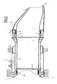
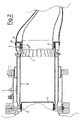
- FIGS. 1 and 2 illustrate a combustion chamber, indicated as a whole with 2, of a gas turbine, inside which a flame pipe of liner 10, according to the present invention, is fixed.
- the flame pipe 10 has a cylindrical structure and is connected at one of its ends to the burner 3 and at the other end to a flow connector or conveyor 4 for the turbine.
- the flame pipe 10 is made of a composite material with a ceramic matrix.
- the flame pipe 10 according to the present invention is preferably made of silicon carbide.
- the fixing system is equipped with two cylindrical elastic heads 5 whose dimension is such as to allow them to be wedged, as shown in figures 1 and 2 , onto the ends of the liner 10.
- cylindrical elastic heads 5 are wedged onto the ends of the liner 10 thanks to appropriate ring-shaped housings or grooves 7 whose size corresponds to that of the end of the liner 1 on which they are inserted.
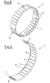
- the two cylindrical elastic heads 5, normally made of a metallic material, are equipped along their circumference, as shown in figures 3 and 4 , with a series of notches 6 arranged parallelly to define a series of teeth 15, attached to an end.
- the notches 6 allow the expansion of the liner 10, in a radial direction.
- Spikes or beads 9 which fit into pass-through radial holes 21 of the head 5 are provided for blocking the heads 5 onto the liner 10, in order to prevent an angular sliding between the head 5 and liner 10.
- the cylindrical elastic heads 5, more clearly visible in figures 3 and 4 are equipped with a cylindrical spring 8 capable of attenuating, during the thermal expansion, the tensions, due to the different material, between the metallic head 5 and liner 10 and exerting a pressure on the internal surface of the liner 10 capable of blocking the head 5 on the liner 10.
- each head 5 situated inside the ring-shaped housing 7, which protrudes on the internal surface of the liner 10.
- the spring 8 is produced as a part of an internal surface of the housing 7.
- the fixing means comprise second cylindrical springs 12, 13.
- cylindrical spring 12 is situated in correspondence with an end of the liner 10, between the burner 3 and the liner 10, so as to rest, in order to exert its fixing action, on the outer surface of the cylindrical head 5, creating a metal-metal contact.
- the other cylindrical spring 13 is situated in correspondence with the other end of the liner 10, between the flow conveyor 4 and the liner 10, so as to rest, in order to exert its fixing action, on the outer surface of the cylindrical head 5, also in this case creating a metal-metal contact.
- Figure 2 illustrates an alternative embodiment of the flame pipe or liner 10 according to the present invention completely analogous to that described above except for the fact that it has a section with a constant diameter and requires, for fixing it onto the flow conveyor 4, a particular cylindrical spring 13' with a sinusoidal profile.
Landscapes
- Engineering & Computer Science (AREA)
- Chemical & Material Sciences (AREA)
- Combustion & Propulsion (AREA)
- Mechanical Engineering (AREA)
- General Engineering & Computer Science (AREA)
- Ceramic Engineering (AREA)
- Combustion Of Fluid Fuel (AREA)
- Fluidized-Bed Combustion And Resonant Combustion (AREA)
- Turbine Rotor Nozzle Sealing (AREA)
- Rigid Pipes And Flexible Pipes (AREA)
Applications Claiming Priority (2)
| Application Number | Priority Date | Filing Date | Title |
|---|---|---|---|
| IT001673A ITMI20031673A1 (it) | 2003-08-28 | 2003-08-28 | Sistema di fissaggio di un tubo di fiamma o "liner". |
| ITMI20031673 | 2003-08-28 |
Publications (3)
| Publication Number | Publication Date |
|---|---|
| EP1564494A2 EP1564494A2 (en) | 2005-08-17 |
| EP1564494A3 EP1564494A3 (en) | 2013-01-16 |
| EP1564494B1 true EP1564494B1 (en) | 2015-01-14 |
Family
ID=34224987
Family Applications (1)
| Application Number | Title | Priority Date | Filing Date |
|---|---|---|---|
| EP04255151.5A Not-in-force EP1564494B1 (en) | 2003-08-28 | 2004-08-26 | Fixing system of a flame pipe or liner |
Country Status (8)
| Country | Link |
|---|---|
| US (1) | US7555906B2 (zh) |
| EP (1) | EP1564494B1 (zh) |
| JP (1) | JP4619065B2 (zh) |
| KR (1) | KR100884125B1 (zh) |
| CN (1) | CN100580321C (zh) |
| CA (1) | CA2478606C (zh) |
| IT (1) | ITMI20031673A1 (zh) |
| NO (1) | NO20043605L (zh) |
Families Citing this family (31)
| Publication number | Priority date | Publication date | Assignee | Title |
|---|---|---|---|---|
| US7647779B2 (en) * | 2005-04-27 | 2010-01-19 | United Technologies Corporation | Compliant metal support for ceramic combustor liner in a gas turbine engine |
| US7546743B2 (en) * | 2005-10-12 | 2009-06-16 | General Electric Company | Bolting configuration for joining ceramic combustor liner to metal mounting attachments |
| US7762076B2 (en) * | 2005-10-20 | 2010-07-27 | United Technologies Corporation | Attachment of a ceramic combustor can |
| US7681403B2 (en) * | 2006-04-13 | 2010-03-23 | General Electric Company | Forward sleeve retainer plate and method |
| US8141370B2 (en) * | 2006-08-08 | 2012-03-27 | General Electric Company | Methods and apparatus for radially compliant component mounting |
| US9127565B2 (en) * | 2008-04-16 | 2015-09-08 | Siemens Energy, Inc. | Apparatus comprising a CMC-comprising body and compliant porous element preloaded within an outer metal shell |
| US8375726B2 (en) * | 2008-09-24 | 2013-02-19 | Siemens Energy, Inc. | Combustor assembly in a gas turbine engine |
| US8745989B2 (en) * | 2009-04-09 | 2014-06-10 | Pratt & Whitney Canada Corp. | Reverse flow ceramic matrix composite combustor |
| US8991192B2 (en) * | 2009-09-24 | 2015-03-31 | Siemens Energy, Inc. | Fuel nozzle assembly for use as structural support for a duct structure in a combustor of a gas turbine engine |
| US8713945B2 (en) | 2010-06-29 | 2014-05-06 | Nuovo Pignone S.P.A. | Liner aft end support mechanisms and spring loaded liner stop mechanisms |
| US9228499B2 (en) * | 2011-08-11 | 2016-01-05 | General Electric Company | System for secondary fuel injection in a gas turbine engine |
| US9243507B2 (en) * | 2012-01-09 | 2016-01-26 | General Electric Company | Late lean injection system transition piece |
| US9435535B2 (en) * | 2012-02-20 | 2016-09-06 | General Electric Company | Combustion liner guide stop and method for assembling a combustor |
| US20130333389A1 (en) * | 2012-06-15 | 2013-12-19 | General Electric Company | Cross fire tube retention system for a gas turbine engine |
| US8707673B1 (en) * | 2013-01-04 | 2014-04-29 | General Electric Company | Articulated transition duct in turbomachine |
| US9416969B2 (en) * | 2013-03-14 | 2016-08-16 | Siemens Aktiengesellschaft | Gas turbine transition inlet ring adapter |
| JP2017520738A (ja) | 2014-04-09 | 2017-07-27 | ゼネラル・エレクトリック・カンパニイ | 燃焼ライナの補修方法及び装置 |
| US9932831B2 (en) * | 2014-05-09 | 2018-04-03 | United Technologies Corporation | High temperature compliant metallic elements for low contact stress ceramic support |
| EP3002519B1 (en) | 2014-09-30 | 2020-05-27 | Ansaldo Energia Switzerland AG | Combustor arrangement with fastening system for combustor parts |
| US10215418B2 (en) * | 2014-10-13 | 2019-02-26 | Ansaldo Energia Ip Uk Limited | Sealing device for a gas turbine combustor |
| US9982821B1 (en) | 2015-01-28 | 2018-05-29 | United Technologies Corporation | Doubled wall pipe flange and coupling configuration |
| KR101662121B1 (ko) | 2015-07-06 | 2016-10-04 | 두산중공업 주식회사 | 라이너와 트랜지션피스 연결부 발명 |
| US10197278B2 (en) | 2015-09-02 | 2019-02-05 | General Electric Company | Combustor assembly for a turbine engine |
| US10168051B2 (en) | 2015-09-02 | 2019-01-01 | General Electric Company | Combustor assembly for a turbine engine |
| DE102015226079A1 (de) * | 2015-12-18 | 2017-06-22 | Dürr Systems Ag | Brennkammervorrichtung und Gasturbinenvorrichtung |
| US10865660B2 (en) * | 2017-09-12 | 2020-12-15 | DOOSAN Heavy Industries Construction Co., LTD | Transition piece support structure, gas turbine combustor including same, and method of installing same |
| US11287239B1 (en) * | 2019-07-26 | 2022-03-29 | The United States Of America As Represented By The Secretary Of The Army | Fast utility access device and method of use thereof |
| CN114543120B (zh) * | 2021-11-30 | 2023-07-18 | 中国航发湖南动力机械研究所 | 一种基于陶瓷基复合材料的火焰筒固定结构 |
| CN114484505B (zh) * | 2022-01-27 | 2023-05-16 | 西安鑫垚陶瓷复合材料有限公司 | 陶瓷基复合材料全环型火焰筒、定型模具及其制备方法 |
| CN115507392B (zh) * | 2022-09-16 | 2024-04-02 | 中国航发湖南动力机械研究所 | 一种陶瓷基复合材料火焰筒与金属件的连接结构 |
| CN116293802B (zh) * | 2023-03-14 | 2024-05-14 | 中国空气动力研究与发展中心空天技术研究所 | 基于激波系点火和回流稳焰的超燃冲压发动机燃烧室 |
Family Cites Families (23)
| Publication number | Priority date | Publication date | Assignee | Title |
|---|---|---|---|---|
| GB612532A (en) * | 1946-04-08 | 1948-11-15 | Adrian Albert Lombard | Improvements in or relating to combustion chambers for internal combustion turbines |
| US3018624A (en) * | 1954-03-02 | 1962-01-30 | Bristol Siddeley Engines Ltd | Flame tubes for use in combustion systems of gas turbine engines |
| GB1423052A (en) * | 1973-03-27 | 1976-01-28 | British Leyland Uk Ltd | Combustion chamber assembly for a gas turbine engine |
| US3910853A (en) * | 1974-07-29 | 1975-10-07 | Fritzsche Dodge & Olcott Inc | 1,1,4,4-Tetra methyl-alkyl-nitriles-tetrahydronaphthalene perfume compositions |
| JPS52158202U (zh) * | 1976-05-27 | 1977-12-01 | ||
| JPS5440909A (en) * | 1977-09-06 | 1979-03-31 | Toshiba Corp | Burner for turbine |
| JPS55126569U (zh) * | 1979-03-05 | 1980-09-08 | ||
| US4413470A (en) * | 1981-03-05 | 1983-11-08 | Electric Power Research Institute, Inc. | Catalytic combustion system for a stationary combustion turbine having a transition duct mounted catalytic element |
| EP0116160B1 (de) * | 1983-01-18 | 1987-12-23 | BBC Brown Boveri AG | Aussengelagerter Abgasturbolader mit ungekühltem Gaskanal |
| JPH01131821A (ja) * | 1987-11-17 | 1989-05-24 | Hitachi Ltd | ガスタービン燃焼器の支承構造 |
| JPH087246Y2 (ja) * | 1989-08-03 | 1996-03-04 | トヨタ自動車株式会社 | セラミック製燃焼器の組立構造 |
| US5291732A (en) * | 1993-02-08 | 1994-03-08 | General Electric Company | Combustor liner support assembly |
| JPH07293276A (ja) | 1994-04-20 | 1995-11-07 | Mitsubishi Heavy Ind Ltd | 燃焼器のスプリングクリップ構造 |
| JPH08284688A (ja) * | 1995-04-18 | 1996-10-29 | Hitachi Ltd | ガスタービンおよびガスタービン燃焼装置 |
| US6116014A (en) * | 1995-06-05 | 2000-09-12 | Catalytica, Inc. | Support structure for a catalyst in a combustion reaction chamber |
| JPH09329337A (ja) * | 1996-06-11 | 1997-12-22 | Hitachi Ltd | ガスタービン燃焼器ライナ |
| JPH10238777A (ja) * | 1997-02-28 | 1998-09-08 | Hitachi Ltd | ガスタービン燃焼器 |
| JP4709433B2 (ja) * | 2001-06-29 | 2011-06-22 | 三菱重工業株式会社 | ガスタービン燃焼器 |
| US6996565B2 (en) * | 2001-09-06 | 2006-02-07 | Initiate Systems, Inc. | System and method for dynamically mapping dynamic multi-sourced persisted EJBs |
| US6910853B2 (en) * | 2002-11-27 | 2005-06-28 | General Electric Company | Structures for attaching or sealing a space between components having different coefficients or rates of thermal expansion |
| US20040255145A1 (en) * | 2003-05-06 | 2004-12-16 | Jerry Chow | Memory protection systems and methods for writable memory |
| US7552277B2 (en) * | 2003-08-20 | 2009-06-23 | International Business Machines Corporation | Distributed buffer integrated cache memory organization and method for reducing energy consumption thereof |
| JP3898685B2 (ja) * | 2003-10-20 | 2007-03-28 | 株式会社東芝 | 半導体記憶装置 |
-
2003
- 2003-08-28 IT IT001673A patent/ITMI20031673A1/it unknown
-
2004
- 2004-08-19 CA CA2478606A patent/CA2478606C/en not_active Expired - Fee Related
- 2004-08-26 EP EP04255151.5A patent/EP1564494B1/en not_active Not-in-force
- 2004-08-26 KR KR1020040067547A patent/KR100884125B1/ko not_active IP Right Cessation
- 2004-08-26 US US10/926,399 patent/US7555906B2/en not_active Expired - Fee Related
- 2004-08-27 JP JP2004247904A patent/JP4619065B2/ja not_active Expired - Fee Related
- 2004-08-27 NO NO20043605A patent/NO20043605L/no not_active Application Discontinuation
- 2004-08-28 CN CN200410085159A patent/CN100580321C/zh not_active Expired - Fee Related
Also Published As
| Publication number | Publication date |
|---|---|
| US20050050902A1 (en) | 2005-03-10 |
| CA2478606A1 (en) | 2005-02-28 |
| ITMI20031673A1 (it) | 2005-02-28 |
| CN100580321C (zh) | 2010-01-13 |
| KR100884125B1 (ko) | 2009-02-17 |
| JP2005077090A (ja) | 2005-03-24 |
| EP1564494A2 (en) | 2005-08-17 |
| EP1564494A3 (en) | 2013-01-16 |
| JP4619065B2 (ja) | 2011-01-26 |
| KR20050021321A (ko) | 2005-03-07 |
| CN1590850A (zh) | 2005-03-09 |
| CA2478606C (en) | 2010-10-12 |
| NO20043605L (no) | 2005-02-28 |
| US7555906B2 (en) | 2009-07-07 |
Similar Documents
| Publication | Publication Date | Title |
|---|---|---|
| EP1564494B1 (en) | Fixing system of a flame pipe or liner | |
| JP4526976B2 (ja) | ターボ機械の高圧タービンのリングスペーサセクタを軸方向に保持するための装置 | |
| US8511972B2 (en) | Seal member for use in a seal system between a transition duct exit section and a turbine inlet in a gas turbine engine | |
| JP6310696B2 (ja) | 複数のタービン部品間の空気の漏れを防止するためのデバイス及び方法 | |
| US6758653B2 (en) | Ceramic matrix composite component for a gas turbine engine | |
| US9127565B2 (en) | Apparatus comprising a CMC-comprising body and compliant porous element preloaded within an outer metal shell | |
| EP1609954B1 (en) | Securing arrangement | |
| US20180073398A1 (en) | Turbine ring assembly made from ceramic matrix composite material | |
| KR100871194B1 (ko) | 회전 기계용 인서트 조립체, 터빈 및 터빈의 인서트 조립체개장 방법 | |
| US6453675B1 (en) | Combustor mounting for gas turbine engine | |
| EP2236929B1 (en) | Combustor | |
| EP1240411B1 (en) | Split ring for tip clearance control | |
| US5195868A (en) | Heat shield for a compressor/stator structure | |
| US20070031249A1 (en) | Gas turbine engine and a rotor for a gas turbine engine | |
| CA2604540C (en) | Reduced stress internal manifold heat shield attachment | |
| US20100064693A1 (en) | Combustor assembly comprising a combustor device, a transition duct and a flow conditioner | |
| US6896484B2 (en) | Turbine engine sealing device | |
| GB2413832A (en) | Exhaust expansion joint | |
| US20090235667A1 (en) | Gas-turbine combustion chamber with ceramic flame tube | |
| EP0926436A2 (en) | Vibration damper | |
| CN113811670A (zh) | 安装在横向构件上的涡轮环组件 | |
| JPH0375414A (ja) | ガスタービン燃焼器 | |
| US10982859B2 (en) | Cross fire tube retention system | |
| GB2422874A (en) | Gas turbine burner expansion bar structure | |
| US20040187500A1 (en) | Suspension device |
Legal Events
| Date | Code | Title | Description |
|---|---|---|---|
| PUAI | Public reference made under article 153(3) epc to a published international application that has entered the european phase |
Free format text: ORIGINAL CODE: 0009012 |
|
| AK | Designated contracting states |
Kind code of ref document: A2 Designated state(s): AT BE BG CH CY CZ DE DK EE ES FI FR GB GR HU IE IT LI LU MC NL PL PT RO SE SI SK TR |
|
| AX | Request for extension of the european patent |
Extension state: AL HR LT LV MK |
|
| PUAL | Search report despatched |
Free format text: ORIGINAL CODE: 0009013 |
|
| AK | Designated contracting states |
Kind code of ref document: A3 Designated state(s): AT BE BG CH CY CZ DE DK EE ES FI FR GB GR HU IE IT LI LU MC NL PL PT RO SE SI SK TR |
|
| AX | Request for extension of the european patent |
Extension state: AL HR LT LV MK |
|
| RIC1 | Information provided on ipc code assigned before grant |
Ipc: F23R 3/00 20060101AFI20121213BHEP Ipc: F23M 5/04 20060101ALI20121213BHEP Ipc: F23R 3/60 20060101ALI20121213BHEP |
|
| 17P | Request for examination filed |
Effective date: 20130716 |
|
| RBV | Designated contracting states (corrected) |
Designated state(s): AT BE BG CH CY CZ DE DK EE ES FI FR GB GR HU IE IT LI LU MC NL PL PT RO SE SI SK TR |
|
| AKX | Designation fees paid |
Designated state(s): CH DE FR GB IT LI NL |
|
| 17Q | First examination report despatched |
Effective date: 20130829 |
|
| GRAP | Despatch of communication of intention to grant a patent |
Free format text: ORIGINAL CODE: EPIDOSNIGR1 |
|
| INTG | Intention to grant announced |
Effective date: 20140818 |
|
| GRAS | Grant fee paid |
Free format text: ORIGINAL CODE: EPIDOSNIGR3 |
|
| GRAA | (expected) grant |
Free format text: ORIGINAL CODE: 0009210 |
|
| AK | Designated contracting states |
Kind code of ref document: B1 Designated state(s): CH DE FR GB IT LI NL |
|
| REG | Reference to a national code |
Ref country code: GB Ref legal event code: FG4D |
|
| REG | Reference to a national code |
Ref country code: CH Ref legal event code: EP |
|
| REG | Reference to a national code |
Ref country code: NL Ref legal event code: T3 |
|
| REG | Reference to a national code |
Ref country code: DE Ref legal event code: R096 Ref document number: 602004046500 Country of ref document: DE Effective date: 20150226 |
|
| REG | Reference to a national code |
Ref country code: FR Ref legal event code: PLFP Year of fee payment: 12 |
|
| PGFP | Annual fee paid to national office [announced via postgrant information from national office to epo] |
Ref country code: NL Payment date: 20150826 Year of fee payment: 12 |
|
| REG | Reference to a national code |
Ref country code: DE Ref legal event code: R097 Ref document number: 602004046500 Country of ref document: DE |
|
| PGFP | Annual fee paid to national office [announced via postgrant information from national office to epo] |
Ref country code: CH Payment date: 20150827 Year of fee payment: 12 Ref country code: DE Payment date: 20150827 Year of fee payment: 12 Ref country code: GB Payment date: 20150827 Year of fee payment: 12 |
|
| PLBE | No opposition filed within time limit |
Free format text: ORIGINAL CODE: 0009261 |
|
| STAA | Information on the status of an ep patent application or granted ep patent |
Free format text: STATUS: NO OPPOSITION FILED WITHIN TIME LIMIT |
|
| PGFP | Annual fee paid to national office [announced via postgrant information from national office to epo] |
Ref country code: FR Payment date: 20150817 Year of fee payment: 12 |
|
| 26N | No opposition filed |
Effective date: 20151015 |
|
| PGFP | Annual fee paid to national office [announced via postgrant information from national office to epo] |
Ref country code: IT Payment date: 20150825 Year of fee payment: 12 |
|
| REG | Reference to a national code |
Ref country code: DE Ref legal event code: R119 Ref document number: 602004046500 Country of ref document: DE |
|
| REG | Reference to a national code |
Ref country code: CH Ref legal event code: PL |
|
| REG | Reference to a national code |
Ref country code: NL Ref legal event code: MM Effective date: 20160901 |
|
| GBPC | Gb: european patent ceased through non-payment of renewal fee |
Effective date: 20160826 |
|
| PG25 | Lapsed in a contracting state [announced via postgrant information from national office to epo] |
Ref country code: LI Free format text: LAPSE BECAUSE OF NON-PAYMENT OF DUE FEES Effective date: 20160831 Ref country code: CH Free format text: LAPSE BECAUSE OF NON-PAYMENT OF DUE FEES Effective date: 20160831 |
|
| REG | Reference to a national code |
Ref country code: FR Ref legal event code: ST Effective date: 20170428 |
|
| PG25 | Lapsed in a contracting state [announced via postgrant information from national office to epo] |
Ref country code: NL Free format text: LAPSE BECAUSE OF NON-PAYMENT OF DUE FEES Effective date: 20160901 |
|
| PG25 | Lapsed in a contracting state [announced via postgrant information from national office to epo] |
Ref country code: GB Free format text: LAPSE BECAUSE OF NON-PAYMENT OF DUE FEES Effective date: 20160826 Ref country code: DE Free format text: LAPSE BECAUSE OF NON-PAYMENT OF DUE FEES Effective date: 20170301 Ref country code: FR Free format text: LAPSE BECAUSE OF NON-PAYMENT OF DUE FEES Effective date: 20160831 |
|
| PG25 | Lapsed in a contracting state [announced via postgrant information from national office to epo] |
Ref country code: IT Free format text: LAPSE BECAUSE OF NON-PAYMENT OF DUE FEES Effective date: 20160826 |