EP1564471A2 - Verbindung einer Schelle mit einem Schlauch - Google Patents
Verbindung einer Schelle mit einem Schlauch Download PDFInfo
- Publication number
- EP1564471A2 EP1564471A2 EP05001577A EP05001577A EP1564471A2 EP 1564471 A2 EP1564471 A2 EP 1564471A2 EP 05001577 A EP05001577 A EP 05001577A EP 05001577 A EP05001577 A EP 05001577A EP 1564471 A2 EP1564471 A2 EP 1564471A2
- Authority
- EP
- European Patent Office
- Prior art keywords
- clamp
- ring
- hose
- projections
- edges
- Prior art date
- Legal status (The legal status is an assumption and is not a legal conclusion. Google has not performed a legal analysis and makes no representation as to the accuracy of the status listed.)
- Granted
Links
Images

Classifications
-
- F—MECHANICAL ENGINEERING; LIGHTING; HEATING; WEAPONS; BLASTING
- F16—ENGINEERING ELEMENTS AND UNITS; GENERAL MEASURES FOR PRODUCING AND MAINTAINING EFFECTIVE FUNCTIONING OF MACHINES OR INSTALLATIONS; THERMAL INSULATION IN GENERAL
- F16L—PIPES; JOINTS OR FITTINGS FOR PIPES; SUPPORTS FOR PIPES, CABLES OR PROTECTIVE TUBING; MEANS FOR THERMAL INSULATION IN GENERAL
- F16L33/00—Arrangements for connecting hoses to rigid members; Rigid hose-connectors, i.e. single members engaging both hoses
- F16L33/02—Hose-clips
- F16L33/08—Hose-clips in which a worm coacts with a part of the hose-encircling member that is toothed like a worm-wheel
-
- F—MECHANICAL ENGINEERING; LIGHTING; HEATING; WEAPONS; BLASTING
- F16—ENGINEERING ELEMENTS AND UNITS; GENERAL MEASURES FOR PRODUCING AND MAINTAINING EFFECTIVE FUNCTIONING OF MACHINES OR INSTALLATIONS; THERMAL INSULATION IN GENERAL
- F16L—PIPES; JOINTS OR FITTINGS FOR PIPES; SUPPORTS FOR PIPES, CABLES OR PROTECTIVE TUBING; MEANS FOR THERMAL INSULATION IN GENERAL
- F16L33/00—Arrangements for connecting hoses to rigid members; Rigid hose-connectors, i.e. single members engaging both hoses
- F16L33/02—Hose-clips
- F16L33/04—Hose-clips tightened by tangentially-arranged threaded pin and nut
-
- Y—GENERAL TAGGING OF NEW TECHNOLOGICAL DEVELOPMENTS; GENERAL TAGGING OF CROSS-SECTIONAL TECHNOLOGIES SPANNING OVER SEVERAL SECTIONS OF THE IPC; TECHNICAL SUBJECTS COVERED BY FORMER USPC CROSS-REFERENCE ART COLLECTIONS [XRACs] AND DIGESTS
- Y10—TECHNICAL SUBJECTS COVERED BY FORMER USPC
- Y10T—TECHNICAL SUBJECTS COVERED BY FORMER US CLASSIFICATION
- Y10T24/00—Buckles, buttons, clasps, etc.
- Y10T24/14—Bale and package ties, hose clamps
- Y10T24/1412—Bale and package ties, hose clamps with tighteners
- Y10T24/1441—Tangential screw
- Y10T24/1443—Adjustable girth
- Y10T24/1445—Step adjustment
- Y10T24/1447—Plural separable parts
Definitions
- the invention relates to a compound of a Clamp with a hose, with a clamp band the clamp between radial, hook-shaped projections locked, which communicates with the hose stand and overlap the edges of the clamp band.
- This connection is used for pre-assembly of the clamp a hose end.
- the invention is based on the object, a compound specify the type mentioned, the simpler Can be produced and largely independent of changes in thickness the hose is.
- this object is achieved in that the protrusions on the edges of a rubber-elastic Ringes are formed, the hose below the Clamp band releasably surrounding under elastic prestressing, and that the thickness of the ring in its axially between the projections range 5% to 9% of Wall thickness of the hose is.
- the hose and the rubber-elastic Ring can be made separately.
- Hoses of different lengths but the same diameter and the same wall thickness is just a mold required, with which a relatively long hose can be produced is. From this hose can be different then long hoses are cut off.
- Such hoses (even those with slightly different Diameters) one comes with the same rubber-elastic Wrestling, for their production as well only one mold is required.
- the clamp has closure for tensioning the clamp band and in front of and behind the shutter two opposite each other hook-shaped projections on the edges of Ringes are formed, which are the edges of the clamp band spread. These two pairs of projections prevent one Displacement of the closure during and before tightening the clamp.
- two more, opposite hook-shaped projections each at one of the edges of the Ringes be formed, which are the edges of the clamp band spill over and from the middle of the two in front and behind the locking projection pairs in both circumferential directions the clamp each to the middle of third projection pair an angular distance of more than 90 °.
- This additional lead pair prevents an inclination of the clamp band when Clamping when the shutter when clamping in the axial direction held by hand while or by a screwdriver loaded in the axial direction of the clamp is, by means of the screwdriver, for. by an axial component when tightening a clamping screw the lock on which the screwdriver accidentally is set at an angle.
- the angular distance in the one circumferential direction the clamp are between 140 ° and 170 °.
- the other circumferential direction of the angular distance is then in Range from 190 ° to 220 °.
- This area is sufficient Place for the arrangement of a spring between Clamp and rubber-elastic ring for balancing a thermal and pressure-related change in thickness of the wall thickness of the hose free.
- a spring is For example, from DE 41 27 017 Cl known.
- the ring on each bead between the projections encircling beads has, whose cross-section radially outwards in each case in opposite axial directions of the ring to the outside and increases radially outward.
- the beads will be not pressured and kept by the clamp therefore their shape largely independent of the clamping pressure the bell at. At the same time they prevent in addition to the hook-shaped projections, an axial displacement the clamp on the rubber-elastic ring.
- the cross section of the beads radially inward, respectively in opposite axial directions of the ring increase outwards and radially inwards. This after inside with respect to the ring protruding parts of the beads cause when clamping the clamp, that the both hook-shaped projections of each projection pair tend towards each other and the clamp band the tighter spread.
- a Hose 1 of which only a short end section shown is, with a clamp, here a worm thread clamp, the closure 2 of a housing. 3 and a clamping screw 4 only shown schematically is, has a rubber-elastic ring 5, which in FIGS. 5 to 8 is shown individually and the Hose 1 releasably surrounds under elastic bias.
- the hose 1 has rubber and possibly also a Tissue insert on. He can only be flexible and compliant thermoplastic. Also, the ring 5 may be made of rubber or plastic.
- the clamp band 6 of the clamp on its outside with (not shown) rib-like threaded portions for the engagement of the thread of the clamping screw 4 is provided and their ends are within of the housing 2 is between radial, about locked hook-shaped projections 7-12.
- the projections 7-12 are formed on the edges of the ring 5.
- the thickness D of the ring 5 is in its axial between the projections 7, 10, 12 on the one hand and the Projections 8, 9, 11 on the other hand lying area 13th (Fig. 5 to 8) about 5% to 9% of the wall thickness of (unloaded) hose 1, here about 6% to about 8% at a thickness D of about 0.3 mm to about 0.4 mm and a wall thickness of the tube 1 of about 5 mm.
- the rubber-elastic ring 5 has at its edges in the circumferential direction between the projections 10-12 circumferential Wommeste 14-19, whose cross-section radially outwards each in opposite axial directions of the ring 5 to the outside and increases radially outward. Furthermore, the Cross section of the beads 14-19 radially inward in opposite Axial directions of the ring 5 to the outside and radially inwards.
- tube 1 and ring 5 has the advantage that they can be made separately. For hoses of different lengths but the same Diameter and same wall thickness is just a mold required. First, a relatively long Hose 1 are produced, from which then different long hoses can be cut off. For all hoses you get the same elastic rubber Wrestling 5, for which also only one mold is required. Since the ring 5 compared to Wall thickness of the hose is relatively thin, affected he not only the overall behavior of tube 1 and Ring 5 hardly, but he can be easily on the Apply hose and together with the hose and the unstrapped preassembled clamp on a pipe socket Slide over a retaining rib of the socket.
- the two projection pairs 7, 8 and 9, 10 prevent one Displacement of the closure 2 at and before the Clamp the clamp.
- the additional projection pair 11, 12 prevents one Inclined position of the clamp band 6 during clamping, when the shutter when clamping in the axial direction with the Hand held while doing or by means of a screwdriver loaded in the axial direction of the clamp, by means of the screwdriver e.g. by an axial component the through the screwdriver when tightening the clamping screw 4 on this exerted pressure force, if the screwdriver accidentally slanted becomes.
- the angular distance ⁇ between the middle of the first two Lead pairs 7, 8 and 9, 10 on the one hand and the third projection pair 11, 12 on the other hand, so that the third projection pair 11, 12 not exactly diametrically the first two pairs of projections is arranged leaves sufficient space for the arrangement of a spring between Clamp and ring 5 in the peripheral region of the ring 5 in a clockwise direction between the projection pair 7, 8 and the projection pair 11, 12, to a thermally and pressure-related change in thickness of the wall thickness of the hose 1 balance.
- a spring is for example from DE 41 27 017 Cl known.
- the approximately triangular cross-sectional shape of the beads 14-19 at the Edge of the outside and inside of the ring 5 between the projections 7-12 requires little material. you will be not directly pressurized by the clamp and therefore keep their shape largely independent of Clamping pressure of the clamp at. At the same time prevent in addition to the hook-shaped projections 7-12 an axial displacement of the clamp on the ring. 5
- the lugs 20 of the projections 7-12 have an oblique inside the ring circumference sloping nose bridge, the insertion of the clamp band 6 between the projections 7-12 relieved due to its slope.
- the ring 5 is in principle also for pre-assembly of others Clamps, e.g. Spring clips or such with Clamping jaws and clamping screw, suitable.
- Clamps e.g. Spring clips or such with Clamping jaws and clamping screw, suitable.
Landscapes
- Engineering & Computer Science (AREA)
- General Engineering & Computer Science (AREA)
- Mechanical Engineering (AREA)
- Joints That Cut Off Fluids, And Hose Joints (AREA)
- Clamps And Clips (AREA)
Abstract
Description
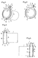
- Fig. 1
- ein Ausführungsbeispiel einer erfindungsgemäßen Verbindung zwischen einem Endabschnitt eines Schlauches und einer Schelle mittels eines gummielastischen Ringes,
- Fig. 2
- eine Vorderansicht der Verbindung nach Fig. 1,
- Fig. 3
- eine Seitenansicht der Verbindung nach Fig. 1 und
- Fig. 4
- die entgegengesetzte Seitenansicht der Verbindung nach Fig. 1,
- Fig. 5
- eine Seitenansicht eines bei der erfindungsgemäßen Verbindung verwendeten gummielastischen Ringes,
- Fig. 6
- den Schnitt VI-VI der Fig. 5,
- Fig. 7
- den Schnitt VII-VII der Fig. 5 und
- Fig. 8
- einen vergrößerten Ausschnitt der Fig. 7.
Claims (7)
- Verbindung einer Schelle mit einem Schlauch (1), bei der ein Schellenband (6) der Schelle zwischen radialen, hakenförmigen Vorsprüngen (7-12) arretiert ist, die mit dem Schlauch (1) in Verbindung stehen und die Ränder des Schellenbands (6) übergreifen, dadurch gekennzeichnet, daß die Vorsprünge (7-12) an den Rändern eines gummielastischen Ringes (5) ausgebildet sind, der den Schlauch (1) unterhalb des Schellenbandes (6) unter elastischer Vorspannung lösbar umgibt, und daß die Dicke (D) des Ringes (5) in seinem axial zwischen den Vorsprüngen (7-12) liegenden Bereich 5 % bis 9 % der Wandstärke des Schlauches (1) beträgt.
- Verbindung nach Anspruch 1, dadurch gekennzeichnet, daß die Schelle einen Verschluß (2) zum Spannen des Schellenbands (6) aufweist und vor und hinter dem Verschluß (2) jeweils zwei sich gegenüberliegende hakenförmige Vorsprünge (7-10) an den Rändern des Ringes (5) angeformt sind, die die Ränder des Schellenbands (6) übergreifen.
- Verbindung nach Anspruch 2, dadurch gekennzeichnet, daß zwei weitere, sich gegenüberliegende hakenförmige Vorsprünge (11, 12) jeweils an einem der Ränder des Ringes (5) angeformt sind, die die Ränder des Schellenbands (6) übergreifen und von der Mitte der beiden vor und hinter dem Verschluß (2) liegenden Vorsprungpaare (7, 8; 9, 10) in beiden Umfangsrichtungen der Schelle jeweils bis zur Mitte des dritten Vorsprungpaares (11, 12) einen Winkelabstand (β) von mehr als 90° aufweisen.
- Verbindung nach Anspruch 3, dadurch gekennzeichnet, daß der Winkelabstand (β) in der einen Umfangsrichtung der Schelle zwischen 140° und 170° liegt.
- Verbindung nach einem der Ansprüche 1 bis 4, dadurch gekennzeichnet, daß der Ring (5) an jedem Rand zwischen den Vorsprüngen (7-12) umlaufende Wülste (14-19) aufweist, deren Querschnitt radial außen jeweils in entgegengesetzten Axialrichtungen des Ringes (5) nach außen und radial nach außen zunimmt.
- Verbindung nach Anspruch 5, dadurch gekennzeichnet, daß der Querschnitt der Wülste (14-19) radial innen jeweils in entgegengesetzten Axialrichtungen des Ringes (5) nach außen und radial nach innen zunimmt.
- Verbindung nach einem der Ansprüche 1 bis 6, dadurch gekennzeichnet, daß die Vorsprünge (7-12) die Schellenbandränder mit Nasen (20) übergreifen, deren Querschnitt zu dem jeweils gegenüberliegenden der Vorsprünge (7-12) hin von radial außen nach radial innen zunimmt.
Applications Claiming Priority (2)
| Application Number | Priority Date | Filing Date | Title |
|---|---|---|---|
| DE102004006658A DE102004006658B3 (de) | 2004-02-11 | 2004-02-11 | Verbindung einer Schelle mit einem Schlauch |
| DE102004006658 | 2004-02-11 |
Publications (3)
| Publication Number | Publication Date |
|---|---|
| EP1564471A2 true EP1564471A2 (de) | 2005-08-17 |
| EP1564471A3 EP1564471A3 (de) | 2006-02-15 |
| EP1564471B1 EP1564471B1 (de) | 2007-01-03 |
Family
ID=33560437
Family Applications (1)
| Application Number | Title | Priority Date | Filing Date |
|---|---|---|---|
| EP05001577A Expired - Lifetime EP1564471B1 (de) | 2004-02-11 | 2005-01-26 | Verbindung einer Schelle mit einem Schlauch |
Country Status (6)
| Country | Link |
|---|---|
| US (1) | US7093328B2 (de) |
| EP (1) | EP1564471B1 (de) |
| JP (1) | JP3998020B2 (de) |
| CA (1) | CA2496397C (de) |
| DE (2) | DE102004006658B3 (de) |
| ES (1) | ES2275243T3 (de) |
Cited By (1)
| Publication number | Priority date | Publication date | Assignee | Title |
|---|---|---|---|---|
| US7946001B2 (en) | 2006-10-12 | 2011-05-24 | Norma Germany Gmbh | Hose clamp |
Families Citing this family (9)
| Publication number | Priority date | Publication date | Assignee | Title |
|---|---|---|---|---|
| US7895565B1 (en) | 2006-03-15 | 2011-02-22 | Jp Morgan Chase Bank, N.A. | Integrated system and method for validating the functionality and performance of software applications |
| DE102006048336B4 (de) | 2006-10-12 | 2013-07-04 | Norma Germany Gmbh | Schlauchschelle |
| JP4851959B2 (ja) * | 2007-02-20 | 2012-01-11 | 東海ゴム工業株式会社 | ホースクランプの保持構造 |
| JP5348641B1 (ja) * | 2012-07-25 | 2013-11-20 | 株式会社トヨックス | 管接続用バンドセット及び緊締バンド用アタッチメント |
| US8757133B2 (en) * | 2012-08-27 | 2014-06-24 | Cummins Intellectual Property, Inc. | Gaseous fuel and intake air mixer for internal combustion engine |
| DE102012020224A1 (de) * | 2012-10-16 | 2014-04-17 | Mann + Hummel Gmbh | Schlauchseitige Verbindungseinrichtung einer Schlauchverbindung und Schlauch |
| US9944415B2 (en) * | 2016-02-20 | 2018-04-17 | Hui Lin | Filling container |
| CN112431978A (zh) * | 2020-12-16 | 2021-03-02 | 李佳佳 | 一种加气机用软管连接装置及其使用方法 |
| JP2024062817A (ja) * | 2022-10-25 | 2024-05-10 | 三桜工業株式会社 | 配管継手 |
Family Cites Families (9)
| Publication number | Priority date | Publication date | Assignee | Title |
|---|---|---|---|---|
| US1694664A (en) * | 1927-09-02 | 1928-12-11 | William H Logan | Hose clamp |
| US2283179A (en) * | 1940-08-14 | 1942-05-19 | Adelbert P Buckingham | Soil pipe hub clamp |
| US2433602A (en) * | 1947-03-26 | 1947-12-30 | Flex O Tube Company | Reusable type hose coupling |
| US3694869A (en) * | 1970-05-22 | 1972-10-03 | Norio Matsura | Tube fastener |
| DE4127017C1 (en) * | 1990-02-22 | 1992-04-23 | Rasmussen Gmbh, 6457 Maintal, De | Hose clip with clamping strip and radial spring - which is integrally formed with clamping strip lug |
| DE19501615A1 (de) * | 1995-01-20 | 1996-08-08 | Porsche Ag | Rohrelement aus elastischem Material |
| DE19533553C2 (de) | 1995-09-11 | 1998-01-29 | Rasmussen Gmbh | Vorrichtung zum Festklemmen eines auf einem Rohrendabschnitt aufgeschobenen Schlauchendabschnitts |
| GB2326920A (en) * | 1997-07-01 | 1999-01-06 | Rasmussen Gmbh | Clamp for clamping a hose on a pipe portion |
| US6695354B2 (en) * | 2000-06-27 | 2004-02-24 | Phoenix Ag | Tube arrangement |
-
2004
- 2004-02-11 DE DE102004006658A patent/DE102004006658B3/de not_active Expired - Fee Related
-
2005
- 2005-01-26 EP EP05001577A patent/EP1564471B1/de not_active Expired - Lifetime
- 2005-01-26 DE DE502005000269T patent/DE502005000269D1/de not_active Expired - Lifetime
- 2005-01-26 US US11/043,383 patent/US7093328B2/en not_active Expired - Fee Related
- 2005-01-26 ES ES05001577T patent/ES2275243T3/es not_active Expired - Lifetime
- 2005-02-09 CA CA002496397A patent/CA2496397C/en not_active Expired - Fee Related
- 2005-02-10 JP JP2005034282A patent/JP3998020B2/ja not_active Expired - Fee Related
Cited By (1)
| Publication number | Priority date | Publication date | Assignee | Title |
|---|---|---|---|---|
| US7946001B2 (en) | 2006-10-12 | 2011-05-24 | Norma Germany Gmbh | Hose clamp |
Also Published As
| Publication number | Publication date |
|---|---|
| DE102004006658B3 (de) | 2005-02-03 |
| CA2496397A1 (en) | 2005-08-11 |
| ES2275243T3 (es) | 2007-06-01 |
| US20050172460A1 (en) | 2005-08-11 |
| EP1564471B1 (de) | 2007-01-03 |
| JP2005226835A (ja) | 2005-08-25 |
| CA2496397C (en) | 2008-04-29 |
| EP1564471A3 (de) | 2006-02-15 |
| JP3998020B2 (ja) | 2007-10-24 |
| DE502005000269D1 (de) | 2007-02-15 |
| US7093328B2 (en) | 2006-08-22 |
Similar Documents
| Publication | Publication Date | Title |
|---|---|---|
| DE3531540C2 (de) | Eine die Trennung verhindernde Rohrverbindung | |
| DE102004032134B4 (de) | Steckkupplung | |
| EP2341273B1 (de) | Rohrklemme | |
| DE69724392T2 (de) | Verfahren zum Verbinden von Rohren | |
| EP1260751A2 (de) | Rohrschelle, insbesondere Rohrkupplung | |
| DE2034325A1 (de) | ||
| DE3543717C2 (de) | ||
| EP2497989A1 (de) | Rohrklemmanordnung | |
| DE102004044917A1 (de) | Lösbare Steckverbindung für Rohrleitungen od. dgl. | |
| DE102004006658B3 (de) | Verbindung einer Schelle mit einem Schlauch | |
| DE202007012036U1 (de) | Verschleißring (Protektor) | |
| DE3443943A1 (de) | Rohrverbindung | |
| DE8519523U1 (de) | Steckkupplung | |
| DE2021626A1 (de) | Flexible Rohrverbindung | |
| DE2718208A1 (de) | Muffenverbindung fuer rohre | |
| EP1798459A1 (de) | Rohrverbindungsvorrichtung aus zwei halbschalenartigen Halteelementen | |
| EP1950480B1 (de) | Rohrschelle | |
| EP2812619B1 (de) | Rohrkupplung | |
| EP1544530B1 (de) | Schlauchkupplung | |
| DE102007049996A1 (de) | Rohrverbindung | |
| EP0905426A2 (de) | Dichtungsvorrichtung zur Durchführung einer Leitung durch eine Wandöffnung | |
| DE102024108365A1 (de) | Rohrverbinder mit Halteeinrichtung | |
| EP0942217B1 (de) | Rohrkupplung | |
| DE19539824C1 (de) | Rohrschelle | |
| DE202005014625U1 (de) | Rohrkupplung zum Verbinden von zwei röhrenförmigen Körpern |
Legal Events
| Date | Code | Title | Description |
|---|---|---|---|
| PUAI | Public reference made under article 153(3) epc to a published international application that has entered the european phase |
Free format text: ORIGINAL CODE: 0009012 |
|
| AK | Designated contracting states |
Kind code of ref document: A2 Designated state(s): AT BE BG CH CY CZ DE DK EE ES FI FR GB GR HU IE IS IT LI LT LU MC NL PL PT RO SE SI SK TR |
|
| AX | Request for extension of the european patent |
Extension state: AL BA HR LV MK YU |
|
| PUAL | Search report despatched |
Free format text: ORIGINAL CODE: 0009013 |
|
| AK | Designated contracting states |
Kind code of ref document: A3 Designated state(s): AT BE BG CH CY CZ DE DK EE ES FI FR GB GR HU IE IS IT LI LT LU MC NL PL PT RO SE SI SK TR |
|
| AX | Request for extension of the european patent |
Extension state: AL BA HR LV MK YU |
|
| 17P | Request for examination filed |
Effective date: 20060114 |
|
| GRAP | Despatch of communication of intention to grant a patent |
Free format text: ORIGINAL CODE: EPIDOSNIGR1 |
|
| AKX | Designation fees paid |
Designated state(s): DE ES IT |
|
| GRAS | Grant fee paid |
Free format text: ORIGINAL CODE: EPIDOSNIGR3 |
|
| GRAA | (expected) grant |
Free format text: ORIGINAL CODE: 0009210 |
|
| AK | Designated contracting states |
Kind code of ref document: B1 Designated state(s): DE ES IT |
|
| REF | Corresponds to: |
Ref document number: 502005000269 Country of ref document: DE Date of ref document: 20070215 Kind code of ref document: P |
|
| REG | Reference to a national code |
Ref country code: ES Ref legal event code: FG2A Ref document number: 2275243 Country of ref document: ES Kind code of ref document: T3 |
|
| RAP2 | Party data changed (patent owner data changed or rights of a patent transferred) |
Owner name: NORMA GERMANY GMBH |
|
| PLBE | No opposition filed within time limit |
Free format text: ORIGINAL CODE: 0009261 |
|
| STAA | Information on the status of an ep patent application or granted ep patent |
Free format text: STATUS: NO OPPOSITION FILED WITHIN TIME LIMIT |
|
| 26N | No opposition filed |
Effective date: 20071005 |
|
| PGFP | Annual fee paid to national office [announced via postgrant information from national office to epo] |
Ref country code: ES Payment date: 20100122 Year of fee payment: 6 |
|
| PGFP | Annual fee paid to national office [announced via postgrant information from national office to epo] |
Ref country code: IT Payment date: 20100123 Year of fee payment: 6 |
|
| PGFP | Annual fee paid to national office [announced via postgrant information from national office to epo] |
Ref country code: DE Payment date: 20100114 Year of fee payment: 6 |
|
| REG | Reference to a national code |
Ref country code: DE Ref legal event code: R119 Ref document number: 502005000269 Country of ref document: DE Effective date: 20110802 |
|
| PG25 | Lapsed in a contracting state [announced via postgrant information from national office to epo] |
Ref country code: IT Free format text: LAPSE BECAUSE OF NON-PAYMENT OF DUE FEES Effective date: 20110126 |
|
| REG | Reference to a national code |
Ref country code: ES Ref legal event code: FD2A Effective date: 20120220 |
|
| PG25 | Lapsed in a contracting state [announced via postgrant information from national office to epo] |
Ref country code: ES Free format text: LAPSE BECAUSE OF NON-PAYMENT OF DUE FEES Effective date: 20110127 |
|
| PG25 | Lapsed in a contracting state [announced via postgrant information from national office to epo] |
Ref country code: DE Free format text: LAPSE BECAUSE OF NON-PAYMENT OF DUE FEES Effective date: 20110802 |