EP2812619B1 - Rohrkupplung - Google Patents
Rohrkupplung Download PDFInfo
- Publication number
- EP2812619B1 EP2812619B1 EP13712918.5A EP13712918A EP2812619B1 EP 2812619 B1 EP2812619 B1 EP 2812619B1 EP 13712918 A EP13712918 A EP 13712918A EP 2812619 B1 EP2812619 B1 EP 2812619B1
- Authority
- EP
- European Patent Office
- Prior art keywords
- pipe coupling
- bridging element
- longitudinal slot
- coupling according
- bridging
- Prior art date
- Legal status (The legal status is an assumption and is not a legal conclusion. Google has not performed a legal analysis and makes no representation as to the accuracy of the status listed.)
- Active
Links
Images

Classifications
-
- F—MECHANICAL ENGINEERING; LIGHTING; HEATING; WEAPONS; BLASTING
- F16—ENGINEERING ELEMENTS AND UNITS; GENERAL MEASURES FOR PRODUCING AND MAINTAINING EFFECTIVE FUNCTIONING OF MACHINES OR INSTALLATIONS; THERMAL INSULATION IN GENERAL
- F16L—PIPES; JOINTS OR FITTINGS FOR PIPES; SUPPORTS FOR PIPES, CABLES OR PROTECTIVE TUBING; MEANS FOR THERMAL INSULATION IN GENERAL
- F16L21/00—Joints with sleeve or socket
- F16L21/002—Sleeves or nipples for pipes of the same diameter; Reduction pieces
- F16L21/005—Sleeves or nipples for pipes of the same diameter; Reduction pieces made of elastic material, e.g. partly or completely surrounded by clamping devices
-
- F—MECHANICAL ENGINEERING; LIGHTING; HEATING; WEAPONS; BLASTING
- F16—ENGINEERING ELEMENTS AND UNITS; GENERAL MEASURES FOR PRODUCING AND MAINTAINING EFFECTIVE FUNCTIONING OF MACHINES OR INSTALLATIONS; THERMAL INSULATION IN GENERAL
- F16L—PIPES; JOINTS OR FITTINGS FOR PIPES; SUPPORTS FOR PIPES, CABLES OR PROTECTIVE TUBING; MEANS FOR THERMAL INSULATION IN GENERAL
- F16L21/00—Joints with sleeve or socket
- F16L21/06—Joints with sleeve or socket with a divided sleeve or ring clamping around the pipe ends
- F16L21/065—Joints with sleeve or socket with a divided sleeve or ring clamping around the pipe ends tightened by tangentially-arranged threaded pins
Definitions
- the invention relates to a pipe coupling according to the preamble of claim 1.
- Pipe couplings serve to connect two mutually facing pipe ends.
- a pipe coupling is also referred to as pipe clamp or clamp.
- sealing inserts are provided, which surround the two pipe ends circumferentially and are held by means of the strained band clamp in the desired position. These sealing inserts can be part of the pipe coupling.
- a pipe coupling which comprises a clamp band which can be placed around the pipe ends and has at its ends radially outwardly projecting connecting portions.
- the bends of the connecting portions define a longitudinal slot having a first longitudinal slot side and a second longitudinal slot side spaced therefrom.
- a clamping mechanism for reducing the inner diameter of the clamp band a screw / nut assembly is provided, wherein the screws are passed through holes in the connecting portions.
- a separate bridging element is provided for bridging the longitudinal slot, the thickness decreases in the direction of the free ends. The flattened end portions of this bridging element penetrate when clamping the pipe coupling between the inside of the clamp band and the sealing insert, wherein the voltage applied to the inside of the clamp band sealing insert is lifted from this area.
- the bridging element is formed by the free end of the clamp band. At the free end of the clamp band, an elastic sealing element is provided.
- a comparable pipe coupling is in the DE 38 43 738 A1 shown.
- a disadvantage of the aforementioned solutions is that arranged on the bridging element elastic sealing element in a pipe coupling which engages a flat sealing insert, fold this sealing insert during clamping of the pipe coupling such or can move that a tightness is no longer guaranteed in each case.
- the bridging element is designed as a separate component and thus substantially the same disadvantages as in the WO 2005/038152 A1 Having described bridging element.
- US 4,365,393 A It is proposed in the region of the tabs which receive the clamping bolt of the clamping mechanism to form radially inwardly open recesses in which in the clamped state of the pipe coupling a bridging element outside the inside of the clamp band arranged, flat sealing insert comes to rest.
- too Bridging element is designed as a separate component and therefore also has the aforementioned disadvantages in this context.
- a disadvantage of the aforementioned solution is that the pipe coupling consists of several separate components.
- the pipe ends to be joined must be threaded into the elastic ring, which is difficult to impossible, especially in limited space during assembly of the pipe coupling.
- the housing segments run in addition to the clamp band over the entire circumference, a large amount of material is needed to produce this coupling. This increases the manufacturing cost, which is a major drawback with a mass product such as such a pipe coupling.
- a disadvantage of the aforementioned solution is that the formed as a separate component inner sleeve extends over the entire circumference and thus the pipe coupling substantially the same disadvantages as in the EP 1 767 842 A2 having described pipe coupling.
- a profile clamp shown as a pipe coupling for connecting two pipe ends, each with an outwardly projecting Pipe flange are provided.
- This profile clamp comprises a clamp band, which has a longitudinal slot with a first longitudinal slot side) and a second longitudinal slot side spaced therefrom, and a clamping mechanism for reducing the inner diameter of the clamp band.
- On the clamp band a plurality of successively extending in the circumferential direction of the clamp band profile segments are provided, which are formed in a trough shape in cross-section for receiving the pipe flanges.
- Object of the present invention is therefore to provide a pipe coupling which does not have the aforementioned disadvantages and in particular is easy to manufacture and easy to install. In this case, damage to a lying within the pipe coupling sealing insert is to be avoided when tightening the pipe coupling and ensure sufficient tightness of the created pipe joint.
- At least one spacer element extending in an arcuate section is fixed in a form-fitting manner on the inside of the clamp band, wherein the edge of the spacer element facing the second longitudinal slot side is arranged at a distance from this second longitudinal slot side and this edge of the spacer element forms a stop for a free end of the bridging element forms.
- the provided on the clamp band bridging element is either formed as a separate, but fixed to the clamp band component or is formed by the corresponding end of the clamp band itself. So that's it Bridging element arranged captive on the clamp band and obstructs the assembly of the pipe coupling in any way.
- the at least one spacer element is advantageously a separate element.
- the at least one spacer element is formed by an elevation or bulge of the clamp band, which protrudes from the inside of the clamp band.
- the at least one spacer element provides in the direction of the second longitudinal slot side a clearance between the sealing insert and the inside of the clamp band for the free end of the bridging element, in which this end can penetrate during clamping of the pipe coupling. In this case, it is ensured that the free end of the bridging element comes to rest outside the outside of the sealing insert and does not displace or even damage it in an undesired manner.
- the arrangement of several, advantageously spaced-apart spacer elements can be advantageous to a clamp band for an advantageous orientation of a coming into the pipe coupling sealing insert.
- This pipe coupling is independent of the type of sealing insert used, so that it can be selected and arranged according to the required boundary conditions as needed.
- the at least one spacer serves as a stop for the free end of the bridging element and thus prevents excessive clamping of the pipe coupling during assembly.
- This stop function is particularly advantageous in plastic pipes in which an excessive tension of the pipe coupling could lead to undesirable deformations of the same in their end.
- the at least one spacer element is positively fixed to the inside of the clamp band, this is securely held on the clamp band in the desired position.
- the at least one spacer element is attached by means of an adhesive or a soldering or welding on the inside of the clamp band.
- the at least one spacer element made of a rigid material, such as a sheet metal or plastic, made, whereby a sufficient size of the desired clearance for the free end of the bridging element remains guaranteed and that essentially under all types of loads on the at least one spacer element.
- the at least one spacer element extends over the entire width of the clamp band, whereby a sufficient size of the desired free space for the free end of the bridging element is ensured not only in the circumferential direction of the clamp band but also transversely thereto.
- the at least one spacer element has a thickness which corresponds to the thickness of the bridging element. This measure also ensures a sufficient size of the desired clearance for the free end of the bridging element.
- the spacer element has a thickness that is different from the thickness of the bridging element.
- the thickness of the spacer element preferably corresponds to at least the thickness of the bridging element in order to create a sufficiently large free space for the free end of the bridging element.
- the distance of the second longitudinal slot side facing edge of the at least one spacer element extends over an angular range of 20 ° to 40 ° and preferably from 25 ° to 35 °, whereby a sufficiently large space for receiving the free end of the bridging element is present.
- a transitional region of the free end of the bridging element is tapered towards this free end, whereby a section of the sealing element or the tube wall penetrating into the created free space does not obstruct this process during clamping of the pipe coupling.
- At least one elevation is provided on the inside of the bridging element, which advantageously already bears in the unstressed state of the pipe coupling after arranging the pipe coupling to the pipe ends on the outside of the sealing element or the Rohraussenwandung.
- the contact surface and thus the friction surface between the bridging element and the outside of the sealing element or the Rohraussenwandung is reduced, so that the pipe coupling is easier clamped.
- a plurality of elevations are provided on the inside of the bridging element, whereby a more uniform spacing of the planar portion of the bridging element and thus a disabling or at least this influencing large-scale support of the bridging element is prevented.
- the at least one elevation or the plurality of elevations run along the arch portion, which slide along the outside of the sealing element or the tube tube wall during clamping of the pipe coupling.
- the at least one survey or the plurality of surveys a free end of the bridging element facing side of the corresponding survey on a bevelled or ramp-shaped configuration.
- the at least one elevation or the plurality of elevations in the direction of the arc section in each case has an extension which is greater than 50% of the extension in the direction of the arc section of the bridging element.
- a pipe coupling of the present type is used for different pipe diameters. With the aforementioned advantageous embodiment it is ensured that even with the use of the pipe coupling with pipe diameters in the larger area, a limited support of the bridging element on the outside of the sealing element or the Rohraussenwandung and thus a simple clamping of the pipe coupling is guaranteed.
- a bridging element having a plurality of elevations these run parallel to one another, whereby such a pipe coupling is simple is clamped.
- a parallel arrangement is advantageous, as this, for example, a distortion of the pipe coupling obstructing squeezing of material of the sealing element or the Rohraussenwandung is prevented.
- the at least one elevation or the plurality of elevations is preferably arranged at a distance from at least one of the edges of the bridging element, advantageously at several edges of the bridging element and particularly advantageously at all edges of the bridging element.
- the at least one elevation or the plurality of elevations is formed as a bead, the bead backing is spaced from the inside of the bridging element and facing the interior of the pipe coupling.
- the bridging element and thus the entire pipe coupling is simple and inexpensive to produce.
- the Figures 1 and 2 show a pipe coupling 11 for connecting two pipe ends.
- the pipe coupling 11 comprises a clamp band 12, which is made of a sheet metal strip.
- the free ends 13 and 14 of the clamp band 12 are directly adjacent to each other in a central region of the clamp band 12 fixed to this in each case with two rivets 15.
- the clamp band 12 is thus guided in a double-layered manner, wherein the corresponding sections of the clamp band 12 lie directly against one another along a semicircular region, for example.
- the free ends 13 and 14 of the clamp band 12 may also be spaced from each other, in which case in the region between these free ends 13 and 14, the clamp band 12 would be only single-layer.
- tabs 16 and 18 are formed, each receiving a clamping bolt 23 and 24 respectively.
- the tab 16 has a longitudinal extent of the clamp band 12 extending slot 17.
- the tab 18 has a longitudinal extent of the clamp band 12 extending slot 19.
- In the clamping bolt 24 is a passage opening 25 for a clamping screw 22 and the clamping bolt 23 is an internally threaded bore 26 for the clamping screw 22 is provided.
- the clamping screw 22 penetrates the slots 17 and 19 in the tabs 16 and 18.
- the clamping screw 22 and the clamping bolts 23 and 24 together form the clamping mechanism 21 for reducing the inner diameter of the clamp band 12th
- the longitudinal slot 31 has a first longitudinal slot side 32, which is determined in this embodiment by the edge formed by the bent-out portion of the tab 16 edge.
- the longitudinal slot 31 further has a second longitudinal slot side 33 which is at a distance from the first longitudinal slot side 32 and which in this exemplary embodiment is defined by the edge formed by the outwardly bent portion of the tab 18.
- a bridging element 36 for bridging the longitudinal slot 31 is set inside the clamp band 12, z. B. soldered or welded.
- the bridging element 36 extends over an arc section starting from the first longitudinal slot side 32 in both circumferential directions and thus also in the direction of the second longitudinal slot side 33.
- the length of the arc section is smaller than the inner circumference of the clamp band 12.
- the bridging element 36 points a free end 37, which is aligned in the direction of the second longitudinal slot side 33.
- the clamp band 12 On the inside of the clamp band 12 also a form-fitting fixed to the inside of the clamp band 12, extending in an arc section spacer 41 is provided, wherein the second longitudinal slot side 33 facing edge 42 of the spacer element 41 is disposed at a distance from this second longitudinal slot side 33.
- This edge 42 of the spacer 41 forms a stop for the free end 37 of the bridging element 36.
- the spacer 41 is made of a rigid material and extends over the entire width of the clamp band 12.
- the spacer 41 has a thickness D, the thickness C of the bridging element 36 corresponds.
- the thickness D of the spacer element 41 may be different from the thickness C of the bridging element 36, wherein advantageously the thickness D of the spacer element 41 is greater than the thickness C of the bridging element 36.
- the distance of the edge 42 of the spacer element 41, which faces the second longitudinal slot side 33, extends over an angular range ⁇ of 20 ° to 40 °, preferably 25 ° to 35 °.
- the pipes to be connected with the pipe clamp (in FIG. 1 if only pipe 6 is shown) are aligned with each other.
- a flat sealing insert 7 is placed to the junction of the tube ends.
- the sealing insert 7 is advantageously designed in its dimensions such that their free ends 8 and 9 in the clamped state of the pipe coupling 11 are close to each other.
- the pipe coupling 11 is placed with open clamping mechanism 21 to the junction of the pipe ends, including the tabs 16 and 18 are pulled apart.
- the clamping screw 22 is passed through the passage opening 25 in the clamping bolt 23 and screwed into the threaded hole in the clamping bolt 23.
- the pipe coupling is clamped, wherein the inner diameter of the clamp band 12 is reduced.
- the free end 37 of the bridging element 36 penetrates into the clearance created by the spacer element 41 between the second longitudinal slot side 33 and the edge 42 of the spacer element 41, without the sealing insert 7 being damaged or displaced thereby.
- the sealing insert 7 is a part of the pipe coupling 11, so that at the same time the sealing insert 7 is mounted when arranging the pipe coupling 11.
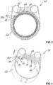
- FIGS. 3 and 4 show a further inventive embodiment of a pipe coupling 51 for connecting two pipe ends.
- the pipe coupling 51 is substantially the same as the previously described pipe coupling 11 except for the design of the bridging element 76. It is therefore referred in this context to the aforementioned embodiments.
- the bridging element 76 fixed on the inside of the clamp band 52 for bridging the longitudinal slot has a free end 77, which is aligned in the direction of the second longitudinal slot side 33.
- the transition region at the free end 77 of the bridging element 76 is tapered towards this free end.
- the projections 78 extend along the arc portion and parallel to each other.
- the elevations 78 each have an extension in the direction of the arc portion of the bridging element 76, which is greater than 50% of the extension in the direction of the arc portion of the bridging element 76.
- the two outer elevations 78 are each spaced from the side edges of the bridging element 76 and all three elevations 78 are also spaced from the free end 77 of the bridging element 76.
- the elevations 78 are each formed as beads.
- the bead backing is in each case spaced from the inside of the bridging element 76 and faces the interior of the pipe coupling 51.
- the second longitudinal slot side facing edge 82 of the spacer element 81 forms a stop for the free end 77 of the bridging element 76.
- a recess 83 (shown in phantom) for receiving the free end 77 of the bridging element 76.
Landscapes
- Engineering & Computer Science (AREA)
- General Engineering & Computer Science (AREA)
- Mechanical Engineering (AREA)
- Mutual Connection Of Rods And Tubes (AREA)
- Clamps And Clips (AREA)
- Joints With Sleeves (AREA)
Description
- Die Erfindung betrifft eine Rohrkupplung nach dem Oberbegriff des Anspruchs 1.
- Rohrkupplungen dienen dem Verbinden zweier einander zugewandten Rohrenden. Eine derartige Rohrkupplung wird auch als Rohrschelle oder Spannschelle bezeichnet. Um die Dichtigkeit der geschaffenen Verbindung sicherzustellen, werden beispielsweise Dichteinlagen vorgesehen, welche die beiden Rohrenden umfänglich umgeben und mittels des verspannten Schellenbandes in der gewünschten Position gehalten werden. Diese Dichteinlagen können ein Bestandteil der Rohrkupplung sein.
- Aus der
WO 2005/038152 A1 ist eine Rohrkupplung bekannt, die ein Schellenband umfasst, das um die Rohrenden herumlegbar ist und an seinen Enden nach radial aussen abragende Verbindungsabschnitte aufweist. Die Abbiegungen der Verbindungsabschnitte definieren einen Längsschlitz mit einer ersten Längsschlitzseite und einer dazu beabstandeten zweiten Längsschlitzseite. Als Spannmechanismus zur Reduktion des Innendurchmessers des Schellenbandes ist eine Schrauben-/Mutteranordnung vorgesehen, wobei die Schrauben durch Löcher in den Verbindungsabschnitten hindurchgeführt sind. Weiter ist ein separates Überbrückungselement zur Überbrückung des Längsschlitzes vorgesehen, dessen Dicke in Richtung der freien Enden abnimmt. Die abgeflachten Endbereiche dieses Überbrückungselementes dringen beim Verspannen der Rohrkupplung zwischen der Innenseite des Schellenbandes und der Dichteinlage ein, wobei die an der Innenseite des Schellenbandes anliegende Dichteinlage von dieser bereichsweise abgehoben wird. - Nachteilig an der vorgenannten Lösung ist, dass das als separates Bauteil ausgebildete Überbrückungselement ohne eine entsprechende Sicherungsmassnahme bei der Montage der Rohrkupplung verloren gehen kann und/oder das Handling dieser Rohrkupplung erschwert. Zudem erfordert dieses Überbrückungselement einen zusätzlichen Herstellungsaufwand und erhöht den Aufwand für das Zusammenbauen (Assembling) der Rohrkupplung. Solche Rohrkupplungen sind Massenprodukte, womit zusätzliche Aufwände einen massgeblichen Nachteil, insbesondere im Hinblick auf eine wirtschaftliche Fertigung darstellen. Weiter neigt aufgrund der Materialeigenschaften der Dichteinlage diese dazu, an der Innenseite des Schellenbandes zu haften, so dass auch mit einem solchen Überbrückungselement beim Verspannen der Rohrkupplung eine Beschädigung der Dichteinlage auftreten kann.
- In einem Ausführungsbeispiel der
US 4,664,428 A ist das Überbrückungselement durch das freie Ende des Schellenbandes gebildet. An dem freien Ende des Schellenbandes ist ein elastisches Dichtelement vorgesehen. Eine vergleichbare Rohrkupplung ist in derDE 38 43 738 A1 gezeigt. - Nachteilig an den vorgenannten Lösungen ist, dass das an dem Überbrückungselement angeordnete elastische Dichtelement bei einer Rohrkupplung, welche eine flächige Dichteinlage umgreift, diese Dichteinlage beim Verspannen der Rohrkupplung derart falten beziehungsweise verschieben kann, dass eine Dichtigkeit nicht mehr in jedem Fall gewährleistet ist.
- In einer alternativen Ausführungsform, welche ebenfalls in der
US 4,664,428 A gezeigt ist, sind beabstandet zu den Längsschlitzseiten innenseitig des Schellenbandes separate Dichtelemente vorgesehen, welche sich beabstandet zu den entsprechenden Seitenrändern des Schellenbandes über einen grossen Teil der Schellenbandbreite erstrecken. Zur Überbrückung des Längsschlitzes ist ein separates Überbrückungselement vorgesehen, welches sich im verspannten Zustand der Rohrkupplung von einer der innenseitig angeordneten Dichtelemente zum anderen Dichtelement erstreckt. - Nachteilig an der vorgenannten Lösung ist, dass das Überbrückungselement als separates Bauteil ausgebildet ist und somit im Wesentlichen die gleichen Nachteile wie das in der
WO 2005/038152 A1 beschriebene Überbrückungselement aufweist. In derUS 4,365,393 A wird vorgeschlagen, im Bereich der Laschen, welche die Spannbolzen des Spannmechanismus aufnehmen, nach radial innen offene Vertiefungen auszubilden, in denen im verspannten Zustand der Rohrkupplung ein Überbrückungselement ausserhalb der innenseitig des Schellenbandes angeordneten, flächigen Dichteinlage zu liegen kommt. - Nachteilig an der vorgenannten Lösung ist, dass neben dem herstellungstechnischen Mehraufwand zur Fertigung der Vertiefungen auch hier das Überbrückungselement als separates Bauteil ausgebildet ist und daher ebenfalls die in diesem Zusammenhang vorgenannten Nachteile aufweist.
- In der
EP 1 767 842 A2 wird vorgeschlagen, bei einer Rohrkupplung zum Verbinden zweier Rohrenden ein mehrsegmentiges Gehäuse über einen elastischen, umfänglich geschlossenen Ring, der als Dichteinlage dient, zusammenzuhalten. Das Gehäuse wird über ein separates aussenliegendes Schellenband verspannt. An der Aussenseite der Gehäusesegmente sind mehrere Vorsprünge vorgesehen, zwischen denen das Schellenband geführt ist. Das Schellenband ist frei um das Gehäuse rotierbar. Im vollständig verspannten Zustand der Kupplung reihen sich alle Gehäusesegmente aneinander und bilden einen geschlossenen Ring aus. - Nachteilig an der vorgenannten Lösung ist, dass die Rohrkupplung aus mehreren separaten Bauteilen besteht. Zudem müssen die zu verbindenden Rohrenden in den elastischen Ring eingefädelt werden, was insbesondere bei beschränkten Platzverhältnissen während einer Montage der Rohrkupplung schwierig bis gar unmöglich ist. Da die Gehäusesegmente zusätzlich zum Schellenband über den gesamten Umfang verlaufen, wird zu der Herstellung dieser Kupplung eine grosse Menge an Material benötigt. Dies erhöht die Herstellungskosten, was bei einem Massenprodukt, wie es eine solche Rohrkupplung darstellt, ein wesentlicher Nachteil ist.
- Aus der
US 2005/0189768 A1 ist eine Rohrkupplung bekannt, welche neben einem aussenliegenden Schellenband eine geschlitzte, über den gesamten Umfang verlaufende Innenhülse aufweist. An den miteinander in Anlage kommenden freien Enden der Innenhülse sind Verriegelungsabschnitte vorgesehen. Am Schellenband wie auch an der Innenhülse sind miteinander in Überlappung bringbare Öffnungen vorgesehen, welche Bolzenabschnitt aufnehmen, die im Bereich der Rohrenden an den Rohren vorgesehen sind. - Nachteilig an der vorgenannten Lösung ist, dass die als separates Bauteil ausgebildete Innenhülse sich über den gesamten Umfang erstreckt und somit die Rohrkupplung im Wesentlichen die gleichen Nachteile wie die in der
EP 1 767 842 A2 beschriebene Rohrkupplung aufweist. - Aus der
EP 1 647 755 A1 ist eine Profilschelle als Rohrkupplung zum Verbinden zweier Rohrenden gezeigt, welche jeweils mit einem nach aussen abragenden Rohrflansch versehen sind. Diese Profilschelle umfasst ein Schellenband, das einen Längsschlitz mit einer ersten Längsschlitzseite) und einer dazu beabstandeten zweiten Längsschlitzseite aufweist, und ein Spannmechanismus zur Reduktion des Innendurchmessers des Schellenbandes. An dem Schellenband sind mehrere hintereinander in Umfangsrichtung des Schellenbandes erstreckende Profilsegmente vorgesehen, welche im Querschnitt trogförmig zur Aufnahme der Rohrflansche ausgebildet sind. In jeder Lücke zwischen den einzelnen Profilsegmenten sind federnde, im Abstand vom Schellenband verlaufende Metallstreifen vorgesehen, um beim Verspannen der Profilschelle die anfänglich exzentrischen Rohre mit ihren Rohrflanschen selbstständig zu zentrieren. Nachteilig an der vorgenannten Lösung ist, dass die Rohrkupplung aus mehreren materialintensiven Bauteilen besteht und nur für die Verbindung von Rohrenden ausgebildet ist, welche entsprechend mit einem Flansch ausgebildet sind. - Aufgabe der vorliegenden Erfindung ist es somit, eine Rohrkupplung zu schaffen, die die vorgenannten Nachteile nicht aufweist und insbesondere einfach herstellbar und montagefreundlich ist. Dabei soll eine Beschädigung einer innerhalb der Rohrkupplung zu liegen kommenden Dichteinlage beim Verspannen der Rohrkupplung vermieden werden und eine ausreichende Dichtigkeit der geschaffenen Rohrverbindung sichergestellt sein.
- Die Aufgabe wird durch die Merkmale des unabhängigen Anspruchs gelöst. Vorteilhafte Weiterbildungen sind in den Figuren und in den abhängigen Patentansprüchen dargelegt.
- Gemäss der Erfindung ist zumindest ein in einem Bogenabschnitt verlaufendes Distanzelement an der Innenseite des Schellenbandes formschlüssig festgelegt, wobei die der zweiten Längsschlitzseite zugewandte Kante des Distanzelementes in einem Abstand zu dieser zweiten Längsschlitzseite angeordnet ist und diese Kante des Distanzelementes einen Anschlag für ein freies Ende des Überbrückungselementes bildet.
- Das an dem Schellenband vorgesehene Überbrückungselement ist entweder als separates, jedoch am Schellenband festgelegtes Bauteil ausgebildet oder wird von dem entsprechenden Ende des Schellenbandes selbst ausgebildet. Somit ist das Überbrückungselement unverlierbar an dem Schellenband angeordnet und behindert die Montage der Rohrkupplung in keinster Weise.
- Das zumindest eine Distanzelement ist vorteilhaft ein separates Element. Alternativ wird das zumindest eine Distanzelement durch eine Erhebung beziehungsweise Ausbuchtung des Schellenbandes gebildet, welche von der Innenseite des Schellenbandes abragt.
- Das zumindest eine Distanzelement stellt in Richtung der zweiten Längsschlitzseite einen Freiraum zwischen der Dichteinlage und der Innenseite des Schellenbandes für das freie Ende des Überbrückungselementes zur Verfügung, in welchen dieses Ende beim Verspannen der Rohrkupplung eindringen kann. Dabei wird sichergestellt, dass das freie Ende des Überbrückungselementes ausserhalb der Aussenseite der Dichteinlage zu liegen kommt und diese nicht in ungewünschter Art und Weise verschiebt oder gar beschädigt. Insbesondere bei Rohrkupplungen mit einem grossen Innendurchmesser kann die Anordnung von mehreren, vorteilhaft beabstandet zueinander angeordneten Distanzelementen an einem Schellenband für eine vorteilhafte Ausrichtung einer in der Rohrkupplung zu liegen kommenden Dichteinlage vorteilhaft sein.
- Diese Rohrkupplung ist unabhängig von der Art der verwendeten Dichteinlage, so dass diese bedarfsweise entsprechend den erforderlichen Randbedingungen ausgewählt und angeordnet werden kann.
- In einer sekundären Funktion dient das zumindest eine Distanzelement als Anschlag für das freie Ende des Überbrückungselementes und verhindert so eine übermässige Verspannung der Rohrkupplung bei der Montage. Diese Anschlagsfunktion ist insbesondere bei Kunststoffrohren vorteilhaft, bei denen eine zu grosse Verspannung der Rohrkupplung zu unerwünschten Verformungen derselben in deren Endbereich führen könnte.
- Da das zumindest eine Distanzelement formschlüssig an der Innenseite des Schellenbandes festgelegt ist, ist dieses sicher an dem Schellenband in der gewünschten Position gehalten. Beispielsweise wird das zumindest eine Distanzelement mittels eines Klebers oder einer Lötung beziehungsweise Schweissung an der Innenseite des Schellenbandes befestigt. In einer weiteren alternativen Ausführungsform wird das zumindest eine Distanzelement mit einem Verbindungsmittel, z. B. zumindest einem Niet oder Clip, an der Innenseite des Schellenbandes festgelegt.
- Vorzugsweise ist das zumindest eine Distanzelement aus einem steifen Material, wie beispielsweise aus einem Blech oder einem Kunststoff, gefertigt, womit eine ausreichende Grösse des gewünschten Freiraums für das freie Ende des Überbrückungselementes gewährleistet bleibt und zwar im Wesentlichen unter allen Arten von Belastungen auf das zumindest eine Distanzelement.
- Bevorzugt erstreckt sich das zumindest eine Distanzelement über die gesamte Breite des Schellenbandes, womit eine ausreichende Grösse des gewünschten Freiraums für das freie Ende des Überbrückungselementes nicht nur in Umfangsrichtung des Schellenbandes sondern auch quer dazu gewährleistet ist.
- Vorzugsweise weist das zumindest eine Distanzelement eine Dicke auf, die der Dicke des Überbrückungselementes entspricht. Auch diese Massnahme stellt eine ausreichende Grösse des gewünschten Freiraums für das freie Ende des Überbrückungselementes sicher.
- In einer alternativen Ausführungsform weist das Distanzelement eine Dicke auf, die unterschiedlich zu der Dicke des Überbrückungselementes ist. Vorzugsweise entspricht die Dicke des Distanzelementes zur Schaffung eines ausreichend grossen Freiraums für das freie Ende des Überbrückungselementes jedoch zumindest der Dicke des Überbrückungselementes.
- Bevorzugt erstreckt sich der Abstand der der zweiten Längsschlitzseite zugewandten Kante des zumindest einen Distanzelementes über einen Winkelbereich von 20° bis 40° und vorzugsweise von 25° bis 35°, womit ein ausreichend grosser Freiraum zur Aufnahme des freien Endes des Überbrückungselementes vorhanden ist.
- Bevorzugt ist ein Übergangsbereich des freien Endes des Überbrückungselementes zu diesem freien Ende hin verjüngend ausgebildet, womit ein in den geschaffenen Freiraum eindringender Abschnitt des Dichtelementes oder der Rohrwandung beim Verspannen der Rohrkupplung diesen Vorgang nicht behindert.
- Vorzugsweise ist zumindest eine Erhebung an der Innenseite des Überbrückungselementes vorgesehen, welche vorteilhaft bereits im unverspannten Zustand der Rohrkupplung nach dem Anordnen der Rohrkupplung an den Rohrenden an der Aussenseite des Dichtelementes beziehungsweise der Rohraussenwandung anliegt. Dadurch wird die Kontaktfläche und somit die Reibungsfläche zwischen dem Überbrückungselement und der Aussenseite des Dichtelementes beziehungsweise der Rohraussenwandung reduziert, womit die Rohrkupplung einfacher verspannbar ist.
- Bevorzugt sind mehrere Erhebungen an der Innenseite des Überbrückungselementes vorgesehen, womit eine gleichmässigere Beabstandung des flächigen Abschnitts des Überbrückungselementes und somit eine die Verspannung behindernde oder zumindest diese beeinflussende grossflächige Auflage des Überbrückungselementes verhindert wird.
- Vorzugsweise verlaufen die zumindest eine Erhebung beziehungsweise die mehreren Erhebungen entlang des Bogenabschnitts, welche beim Verspannen der Rohrkupplung entlang der Aussenseite des Dichtelementes beziehungsweise der Rohraussenwandung gleiten. Insbesondere bei dieser Ausgestaltung der zumindest einen Erhebung beziehungsweise der mehreren Erhebungen weist ein dem freien Ende des Überbrückungselementes zugewandte Seite der entsprechenden Erhebung eine abgeschrägte oder rampenförmige Ausgestaltung auf.
- Bevorzugt weist die zumindest eine Erhebung beziehungsweise die mehreren Erhebungen in Richtung des Bogenabschnitts jeweils eine Erstreckung auf, die grösser als 50% der Erstreckung in Richtung des Bogenabschnitts des Überbrückungselementes ist. Eine Rohrkupplung der vorliegenden Art wird für verschiedene Rohrdurchmesser verwendet. Mit der vorgenannten vorteilhaften Ausführungsform wird gewährleistet, dass auch bei der Verwendung der Rohrkupplung bei Rohrdurchmessern im grösseren Bereich, eine begrenzte Auflage des Überbrückungselementes an der Aussenseite des Dichtelementes beziehungsweise der Rohraussenwandung und somit ein einfaches Verspannen der Rohrkupplung gewährleistet ist.
- Vorzugsweise verlaufen bei einem Überbrückungselement mit mehreren Erhebungen diese parallel zueinander, womit eine solche Rohrkupplung einfach verspannbar ist. Insbesondere bei Erhebungen, welche in Richtung des Bogenabschnitts verlaufen, ist eine parallele Anordnung vorteilhaft, da dadurch beispielsweise ein das Verspannen der Rohrkupplung behinderndes Verquetschen von Material des Dichtelementes oder der Rohraussenwandung verhindert wird.
- Bevorzugt ist die zumindest eine Erhebung beziehungsweise sind die mehreren Erhebungen beabstandet zu zumindest einem der Ränder des Überbrückungselementes angeordnet, vorteilhaft zu mehreren Rändern des Überbrückungselementes und besonders vorteilhaft zu allen Rändern des Überbrückungselementes beabstandet.
- Vorzugsweise ist die zumindest eine Erhebung beziehungsweise sind die mehreren Erhebungen als Sicke ausgebildet, deren Sickenrücken von der Innenseite des Überbrückungselementes beabstandet und dem Innenraum der Rohrkupplung zugewandt ist. Dadurch ist das Überbrückungselement und somit die gesamte Rohrkupplung einfach und kostengünstig herstellbar.
- Weitere Vorteile, Merkmale und Einzelheiten der Erfindung ergeben sich aus der nachfolgenden Beschreibung, in der unter Bezugnahme auf die Zeichnungen Ausführungsbeispiele der Erfindung beschrieben sind. Dabei können die in den Ansprüchen und in der Beschreibung erwähnten Merkmale jeweils einzeln für sich oder in beliebiger Kombination erfindungswesentlich sein.
- Die Bezugszeichenliste ist Bestandteil der Offenbarung. Die Figuren werden zusammenhängend und übergreifend beschrieben. Gleiche Bezugszeichen bedeuten gleiche Bauteile.
- Es zeigen dabei:
- Fig. 1
- Eine erfindungsgemässe Rohrkupplung im montierten Zustand in einer Seitenansicht,
- Fig. 2
- die Rohrkupplung gemäss
Figur 1 in einer perspektivischen Darstellung, - Fig. 3
- eine Variante einer erfindungsgemässe Rohrkupplung im montierten Zustand in einer Seitenansicht, und
- Fig. 4
- die Rohrkupplung gemäss
Figur 3 in einer perspektivischen Darstellung. - Die
Figuren 1 und 2 zeigen eine Rohrkupplung 11 zum Verbinden zweier Rohrenden. Die Rohrkupplung 11 umfasst ein Schellenband 12, das aus einem Blechstreifen gefertigt ist. Die freien Enden 13 und 14 des Schellenbandes 12 sind direkt benachbart zueinander in einem mittleren Bereich des Schellenbandes 12 an diesem jeweils mit zwei Nieten 15 festgelegt. Das Schellenband 12 ist somit doppellagig geführt, wobei etwa entlang eines halbkreisförmigen Bereichs die entsprechenden Abschnitte des Schellenbandes 12 direkt aneinander liegen. Alternativ können die freien Enden 13 und 14 des Schellenbandes 12 auch beabstandet zueinander sein, wobei dann in dem Bereich zwischen diesen freien Enden 13 und 14 das Schellenband 12 nur einlagig wäre. - In den umgebogenen Bereichen des Schellenbandes 12 sind Laschen 16 bzw. 18 ausgebildet, welche jeweils einen Spannbolzen 23 bzw. 24 aufnehmen. Die Lasche 16 weist einen in Längserstreckung des Schellenbandes 12 verlaufenden Schlitz 17 auf. Die Lasche 18 weist einen in Längserstreckung des Schellenbandes 12 verlaufenden Schlitz 19 auf. In dem Spannbolzen 24 ist eine Durchführöffnung 25 für eine Spannschraube 22 und im Spannbolzen 23 ist eine Innengewindebohrung 26 für die Spannschraube 22 vorgesehen. Die Spannschraube 22 durchdringt die Schlitze 17 und 19 in den Laschen 16 bzw. 18. Die Spannschraube 22 sowie die Spannbolzen 23 und 24 bilden zusammen den Spannmechanismus 21 zur Reduktion des Innendurchmessers des Schellenbandes 12.
- Zwischen den Laschen 16 und 18 ist ein Längsschlitz 31 ausgebildet. Der Längsschlitz 31 weist eine erste Längsschlitzseite 32, welche in diesem Ausführungsbeispiel durch die von dem nach aussen abgebogenen Abschnitt der Lasche 16 ausgebildete Kante bestimmt ist. Der Längsschlitz 31 weist weiter eine zu der ersten Längsschlitzseite 32 beabstandete zweite Längsschlitzseite 33 auf, welche in diesem Ausführungsbeispiel durch die von dem nach aussen abgebogenen Abschnitt der Lasche 18 ausgebildete Kante bestimmt ist.
- Weiter ist innenseitig des Schellenbandes 12 ein Überbrückungselement 36 zur Überbrückung des Längsschlitzes 31 festgelegt, z. B. angelötet oder angeschweisst. Das Überbrückungselement 36 erstreckt sich über einen Bogenabschnitt ausgehend von der ersten Längsschlitzseite 32 in beide Umfangsrichtungen und somit auch in Richtung der zweiten Längsschlitzseite 33. Die Länge des Bogenabschnitt ist kleiner als der Innenumfang des Schellenbandes 12. Das Überbrückungselement 36 weist ein freies Ende 37 auf, das in Richtung der zweiten Längsschlitzseite 33 ausgerichtet ist.
- An der Innenseite des Schellenbandes 12 ist zudem ein formschlüssig an der Innenseite des Schellenbandes 12 festgelegtes, in einem Bogenabschnitt verlaufendes Distanzelement 41 vorgesehen, wobei die der zweiten Längsschlitzseite 33 zugewandte Kante 42 des Distanzelementes 41 in einem Abstand zu dieser zweiten Längsschlitzseite 33 angeordnet ist. Diese Kante 42 des Distanzelementes 41 bildet einen Anschlag für das freie Ende 37 des Überbrückungselementes 36. Das Distanzelement 41 ist aus einem steifen Material gefertigt und erstreckt sich über die gesamte Breite des Schellenbandes 12. Das Distanzelement 41 weist eine Dicke D auf, die der Dicke C des Überbrückungselementes 36 entspricht. In einer Alternative kann die Dicke D des Distanzelementes 41 unterschiedlich zur Dicke C des Überbrückungselementes 36 sein, wobei vorteilhaft die Dicke D des Distanzelementes 41 grösser als die Dicke C des Überbrückungselementes 36 ist. Der Abstand der Kante 42 des Distanzelementes 41, die der zweiten Längsschlitzseite 33 zugewandt ist, erstreckt sich über einen Winkelbereich α von 20° bis 40°, vorzugsweise von 25° bis 35°.
- Die mit der Rohrschelle zu verbindenden Rohre (in
Figur 1 ist nur das Rohr 6 dargestellt) werden zueinander ausgerichtet. Um die Stossstelle der Rohrenden wird eine flächige Dichteinlage 7 gelegt. Die Dichteinlage 7 ist in ihren Abmessungen vorteilhaft derart ausgestaltet, dass deren freie Enden 8 bzw. 9 im verspannten Zustand der Rohrkupplung 11 dicht aneinander liegen. Dann wird die Rohrkupplung 11 mit geöffneten Spannmechanismus 21 um die Stossstelle der Rohrenden gelegt, wozu die Laschen 16 und 18 auseinandergezogen werden. Nachdem das Schellenband 12 entsprechend ausgerichtet ist, wird die Spannschraube 22 durch die Durchführöffnung 25 im Spannbolzen 23 hindurchgeführt und in die Gewindebohrung im Spannbolzen 23 eingeschraubt. Durch weiteres Einschrauben der Spannschraube 22 wird die Rohrkupplung verspannt, wobei der Innendurchmessers des Schellenbandes 12 reduziert wird. Das freie Ende 37 des Überbrückungselementes 36 dringt in den von dem Distanzelement 41 geschaffenen, zwischen der zweiten Längsschlitzseite 33 und der Kante 42 des Distanzelementes 41 vorhandenen Freiraum ein, ohne dass die Dichteinlage 7 dadurch beschädigt oder verschoben wird. - In einer Variante ist die Dichteinlage 7 ein Bestandteil der Rohrkupplung 11, so dass beim Anordnen der Rohrkupplung 11 gleichzeitig die Dichteinlage 7 montiert wird.
- Die
Figuren 3 und 4 zeigen eine weitere erfindungsgemässe Ausführungsform einer Rohrkupplung 51 zum Verbinden zweier Rohrenden. Die Rohrkupplung 51 ist bis auf die Ausgestaltung des Überbrückungselementes 76 im Wesentlichen wie die zuvor beschriebene Rohrkupplung 11 ausgebildet. Es wird daher in diesem Zusammenhang auf die vorgenannten Ausführungen verwiesen. - Das innenseitig des Schellenbandes 52 festgelegte Überbrückungselement 76 zur Überbrückung des Längsschlitzes weist ein freies Ende 77 auf, das in Richtung der zweiten Längsschlitzseite 33 ausgerichtet ist. Der Übergangsbereich beim freien Endes 77 des Überbrückungselementes 76 ist zu diesem freien Ende hin verjüngend ausgebildet.
- An der Innenseite des Überbrückungselementes 76 sind mehrere, hier beispielhaft drei Erhebungen 78 vorgesehen. Die Erhebungen 78 verlaufen entlang des Bogenabschnitts und parallel zueinander. Die Erhebungen 78 weisen jeweils eine Erstreckung in Richtung des Bogenabschnitts des Überbrückungselementes 76 auf, die grösser als 50% der Erstreckung in Richtung des Bogenabschnitts des Überbrückungselementes 76 ist. Die beiden äusseren Erhebungen 78 sind jeweils beabstandet zu den Seitenrändern des Überbrückungselementes 76 und alle drei Erhebungen 78 sind auch beabstandet zum freien Ende 77 des Überbrückungselementes 76 angeordnet. Die Erhebungen 78 sind jeweils als Sicken ausgebildet. Deren Sickenrücken ist jeweils von der Innenseite des Überbrückungselementes 76 beabstandet und dem Innenraum der Rohrkupplung 51 zugewandt.
- Die der zweiten Längsschlitzseite zugewandte Kante 82 des Distanzelementes 81 bildet einen Anschlag für das freie Ende 77 des Überbrückungselementes 76. An der Kante 82 des Distanzelementes 81 kann eine Ausnehmung 83 (gestrichelt dargestellt) zur Aufnahme des freien Endes 77 des Überbrückungselementes 76 vorgesehen sein.
Bezugszeichenliste 6 Rohr C Dicke v. 36 7 Dichteinlage D Dicke v. 41 8 freies Ende v. 7 9 freies Ende v. 7 α Winkelbereich 11 Rohrkupplung 12 Schellenband 13 freies Ende v. 12 51 Rohrkupplung 14 freies Ende v. 12 52 Schellenband 15 Niet 16 Lasche 76 Überbrückungselement 17 Schlitz v. 16 77 freies Ende v. 76 18 Lasche 78 Erhebung an 76 19 Schlitz v. 18 81 Distanzelement 21 Spannmechanismus 82 Kante v. 81 22 Spannschraube 83 Ausnehmung bei 82 23 Spannbolzen 24 Spannbolzen 25 Durchführöffnung in 24 26 Gewindebohrung in 23 31 Längsschlitz 32 1. Längsschlitzseite 33 2. Längsschlitzseite 36 Überbrückungselement 37 freies Ende v. 36 41 Distanzelement 42 Kante v. 41
Claims (15)
- Rohrkupplung zum Verbinden zweier Rohrenden umfassend ein Schellenband (12; 52), das einen Längsschlitz (31) mit einer ersten Längsschlitzseite (32) und einer dazu beabstandeten zweiten Längsschlitzseite (33) aufweist, und ein Spannmechanismus (21) zur Reduktion des Innendurchmessers des Schellenbandes (12) sowie ein Überbrückungselement (36; 76) zur Überbrückung des Längsschlitzes (31), das an der Innenseite des Schellenbandes (12; 52) vorgesehen ist und sich von der ersten Längsschlitzseite (32) in Richtung der zweiten Längsschlitzseite (33) über einen Bogenabschnitt erstreckt, wobei die Länge des Bogenabschnitts kleiner als der Innenumfang des Schellenbandes (12; 52) ist, dadurch gekennzeichnet, dass das Überbrückungselement (36; 76) an dem Schellenband (12; 52) und zumindest ein in einem Bogenabschnitt verlaufendes Distanzelement (41; 81) an der Innenseite des Schellenbandes (12) festgelegt sind, wobei die der zweiten Längsschlitzseite (33) zugewandte Kante (42; 82) des Distanzelementes (41; 81) in einem Abstand zu dieser zweiten Längsschlitzseite (33) angeordnet ist und diese Kante (42; 82) des Distanzelementes (41; 81) einen Anschlag für ein freies Ende (37; 77) des Überbrückungselementes (36; 76) bildet.
- Rohrkupplung nach Anspruch 1, dadurch gekennzeichnet, dass das zumindest eine Distanzelement (41; 81) aus einem steifen Material gefertigt ist.
- Rohrkupplung nach Anspruch 1 oder 2, dadurch gekennzeichnet, dass das zumindest eine Distanzelement (41; 81) sich über die gesamte Breite des Schellenbandes (12; 52) erstreckt.
- Rohrkupplung nach einem der Ansprüche 1 bis 3, dadurch gekennzeichnet, dass das zumindest eine Distanzelement (41; 81) eine Dicke (D) aufweist, die der Dicke (C) des Überbrückungselementes (36; 76) entspricht oder unterschiedlich zu der Dicke des Überbrückungselementes ist, wobei vorzugsweise die Dicke (D) des Distanzelementes (41; 81) zumindest der Dicke (C) des Überbrückungselementes (36; 76) entspricht.
- Rohrkupplung nach einem der Ansprüche 1 bis 4, dadurch gekennzeichnet, dass der Abstand der der zweiten Längsschlitzseite (33) zugewandten Kante (42; 82) des zumindest einen Distanzelementes (41; 81) sich über einen Winkelbereich (α) von 20° bis 40°, vorzugsweise von 25° bis 35° erstreckt.
- Rohrkupplung nach einem der Ansprüche 1 bis 5, dadurch gekennzeichnet, dass das zumindest eine Distanzelement (41; 81) formschlüssig an der Innenseite des Schellenbandes (12; 52) festgelegt ist.
- Rohrkupplung nach einem der Ansprüche 1 bis 6, dadurch gekennzeichnet, dass das Distanzelement (81) an seiner der zweiten Längsschlitzseite zugewandte Kante (82) eine Ausnehmung (83) zur Aufnahme des freien Endes (77) des Überbrückungselementes (76) aufweist.
- Rohrkupplung nach einem der Ansprüche 1 bis 7, dadurch gekennzeichnet, dass ein Übergangsbereich beim freien Ende (77) des Überbrückungselementes (76) zu diesem freien Ende (77) hin verjüngend ausgebildet ist.
- Rohrkupplung nach einem der Ansprüche 1 bis 8, dadurch gekennzeichnet, dass zumindest eine Erhebung (78) an der Innenseite des Überbrückungselementes (76) vorgesehen ist.
- Rohrkupplung nach Anspruch 9, dadurch gekennzeichnet, dass mehrere Erhebungen (78) an der Innenseite des Überbrückungselementes (76) vorgesehen sind.
- Rohrkupplung nach Anspruch 9 oder 10, dadurch gekennzeichnet, dass die zumindest eine Erhebung (78) bzw. die mehreren Erhebungen (78) entlang des Bogenabschnitts verlaufen.
- Rohrkupplung nach Anspruch 11, dadurch gekennzeichnet, dass die zumindest eine Erhebung (78) bzw. die mehreren Erhebungen (78) jeweils eine Erstreckung in Richtung des Bogenabschnitts des Überbrückungselementes (76) aufweisen, die grösser als 50% der Erstreckung in Richtung des Bogenabschnitts des Überbrückungselementes (76) ist.
- Rohrkupplung nach einem der Ansprüche 10 bis 12, dadurch gekennzeichnet, dass die mehreren Erhebungen (78) parallel zueinander verlaufen.
- Rohrkupplung nach einem der Ansprüche 9 bis 13, dadurch gekennzeichnet, dass die zumindest eine Erhebung (78) bzw. die mehreren Erhebungen (78) beabstandet zu zumindest einem der Ränder des Überbrückungselementes (76) angeordnet ist bzw. sind.
- Rohrkupplung nach einem der Ansprüche 9 bis 14, dadurch gekennzeichnet, dass die zumindest eine Erhebung (78) bzw. die mehreren Erhebungen (78) als Sicke ausgebildet sind, deren Sickenrücken von der Innenseite des Überbrückungselementes (76) beabstandet und dem Innenraum der Rohrkupplung (51) zugewandt ist.
Priority Applications (1)
| Application Number | Priority Date | Filing Date | Title |
|---|---|---|---|
| EP13712918.5A EP2812619B1 (de) | 2012-02-10 | 2013-02-07 | Rohrkupplung |
Applications Claiming Priority (3)
| Application Number | Priority Date | Filing Date | Title |
|---|---|---|---|
| EP12154836 | 2012-02-10 | ||
| PCT/IB2013/051026 WO2013118079A1 (de) | 2012-02-10 | 2013-02-07 | Rohrkupplung |
| EP13712918.5A EP2812619B1 (de) | 2012-02-10 | 2013-02-07 | Rohrkupplung |
Publications (2)
| Publication Number | Publication Date |
|---|---|
| EP2812619A1 EP2812619A1 (de) | 2014-12-17 |
| EP2812619B1 true EP2812619B1 (de) | 2017-06-28 |
Family
ID=48014126
Family Applications (1)
| Application Number | Title | Priority Date | Filing Date |
|---|---|---|---|
| EP13712918.5A Active EP2812619B1 (de) | 2012-02-10 | 2013-02-07 | Rohrkupplung |
Country Status (4)
| Country | Link |
|---|---|
| EP (1) | EP2812619B1 (de) |
| JP (1) | JP2015511301A (de) |
| RU (1) | RU2607422C2 (de) |
| WO (1) | WO2013118079A1 (de) |
Families Citing this family (4)
| Publication number | Priority date | Publication date | Assignee | Title |
|---|---|---|---|---|
| FR3062702B1 (fr) * | 2017-02-07 | 2020-08-21 | Caillau Ets | Dispositif pour l'accouplement de deux tubes avec pre-montage |
| ES2921929T3 (es) * | 2017-03-31 | 2022-09-02 | Straub Werke Ag | Acoplamiento de tubos |
| RU209374U1 (ru) * | 2021-07-13 | 2022-03-15 | Общество с ограниченной ответственностью "МУФТЫ НСК" | Трубная муфта |
| RU208758U1 (ru) * | 2021-08-10 | 2022-01-12 | Вячеслав Алексеевич Медведев | Устройство для ремонта трубопроводов |
Family Cites Families (10)
| Publication number | Priority date | Publication date | Assignee | Title |
|---|---|---|---|---|
| US4365393A (en) | 1981-05-11 | 1982-12-28 | Mueller Co. | Single and multiple section pipe repair clamps |
| US4664428A (en) * | 1986-04-01 | 1987-05-12 | Brico Industries, Inc. | Sealing assembly for pipe joint |
| DE3843738A1 (de) * | 1987-12-29 | 1989-07-20 | Mannesmann Ag | Klemme zum verbinden starrer metallrohre |
| CH681318A5 (de) * | 1990-03-20 | 1993-02-26 | Straub Federnfabrik | |
| DK0551587T3 (da) * | 1992-01-15 | 1995-11-13 | Straub Federnfabrik | Rørkobling |
| EP1680558A4 (de) | 2003-10-17 | 2007-03-28 | Byung-Moo An | Bandvorrichtung zur verbindung von rohr zur verhinderung von leckage |
| US7490871B2 (en) | 2004-02-26 | 2009-02-17 | Breeze-Torca Products, Llc | Pipe clamp with button engagement hole |
| DE102004050300B4 (de) * | 2004-10-15 | 2009-02-12 | Norma Germany Gmbh | Profilschelle |
| JP4699150B2 (ja) * | 2005-09-16 | 2011-06-08 | 日本ヴィクトリック株式会社 | ハウジング形管継手 |
| JP4701073B2 (ja) * | 2005-11-14 | 2011-06-15 | ショーボンドカップリング株式会社 | 管継手に於けるスライド板の構造 |
-
2013
- 2013-02-07 RU RU2014136721A patent/RU2607422C2/ru active
- 2013-02-07 JP JP2014556178A patent/JP2015511301A/ja active Pending
- 2013-02-07 EP EP13712918.5A patent/EP2812619B1/de active Active
- 2013-02-07 WO PCT/IB2013/051026 patent/WO2013118079A1/de not_active Ceased
Also Published As
| Publication number | Publication date |
|---|---|
| JP2015511301A (ja) | 2015-04-16 |
| WO2013118079A4 (de) | 2013-10-10 |
| WO2013118079A1 (de) | 2013-08-15 |
| RU2607422C2 (ru) | 2017-01-10 |
| RU2014136721A (ru) | 2016-03-27 |
| EP2812619A1 (de) | 2014-12-17 |
Similar Documents
| Publication | Publication Date | Title |
|---|---|---|
| EP1852643B1 (de) | Schelle zum Befestigen eines rohr- oder schlauchförmigen Gegenstandes | |
| EP2674656B1 (de) | Profilschelle | |
| EP0975908B1 (de) | Rohrschelle | |
| EP2584240B1 (de) | Profilschelle mit dichtelement | |
| DE3404739C1 (de) | Steckkupplung zum Verbinden der Enden zweier Rohre | |
| EP2757299B1 (de) | Rohrklemme | |
| EP2839197B1 (de) | Spanngurt und rohrkupplung zum kraftschlüssigen verbinden von rohren, insbesondere von glattendigen rohren | |
| CH664612A5 (de) | Steckkupplung zum verbinden der enden zweier rohre. | |
| CH708163A2 (de) | Spann- oder Rohrschelle. | |
| EP2812619B1 (de) | Rohrkupplung | |
| EP1647755A1 (de) | Profilschelle | |
| EP3601865B1 (de) | Rohrkupplung | |
| CH622597A5 (en) | Socket connection for pipes or pipe fittings | |
| WO2018036937A1 (de) | Sicherungskralle | |
| DE102010040488A1 (de) | Montageeinheit | |
| DE102005000720B4 (de) | Rohrpresskupplung | |
| EP4151895B1 (de) | Zugfeste rohrverbindung | |
| EP0942217B1 (de) | Rohrkupplung | |
| WO2024126087A1 (de) | Spreizverbinder | |
| WO2000017558A1 (de) | Rohrkupplung oder rohrschelle | |
| DE102006029242B4 (de) | Flanschverbindung | |
| DE10021179C2 (de) | Vorrichtung zur axialen Befestigung eines Rohres | |
| DE202016000436U1 (de) | Rohrkupplung zum Verbinden von zwei röhrenförmigen Körpern | |
| DE19929016A1 (de) | Schnellbefestigungsmutter | |
| EP3048353B1 (de) | Rohrkupplung zum Verbinden zweier Rohrenden beziehungsweise Rohrschelle zum Abdichten eines defekten Rohres |
Legal Events
| Date | Code | Title | Description |
|---|---|---|---|
| PUAI | Public reference made under article 153(3) epc to a published international application that has entered the european phase |
Free format text: ORIGINAL CODE: 0009012 |
|
| 17P | Request for examination filed |
Effective date: 20140910 |
|
| AK | Designated contracting states |
Kind code of ref document: A1 Designated state(s): AL AT BE BG CH CY CZ DE DK EE ES FI FR GB GR HR HU IE IS IT LI LT LU LV MC MK MT NL NO PL PT RO RS SE SI SK SM TR |
|
| AX | Request for extension of the european patent |
Extension state: BA ME |
|
| DAX | Request for extension of the european patent (deleted) | ||
| 17Q | First examination report despatched |
Effective date: 20160112 |
|
| GRAJ | Information related to disapproval of communication of intention to grant by the applicant or resumption of examination proceedings by the epo deleted |
Free format text: ORIGINAL CODE: EPIDOSDIGR1 |
|
| STAA | Information on the status of an ep patent application or granted ep patent |
Free format text: STATUS: GRANT OF PATENT IS INTENDED |
|
| GRAP | Despatch of communication of intention to grant a patent |
Free format text: ORIGINAL CODE: EPIDOSNIGR1 |
|
| INTG | Intention to grant announced |
Effective date: 20170420 |
|
| GRAS | Grant fee paid |
Free format text: ORIGINAL CODE: EPIDOSNIGR3 |
|
| GRAA | (expected) grant |
Free format text: ORIGINAL CODE: 0009210 |
|
| STAA | Information on the status of an ep patent application or granted ep patent |
Free format text: STATUS: THE PATENT HAS BEEN GRANTED |
|
| AK | Designated contracting states |
Kind code of ref document: B1 Designated state(s): AL AT BE BG CH CY CZ DE DK EE ES FI FR GB GR HR HU IE IS IT LI LT LU LV MC MK MT NL NO PL PT RO RS SE SI SK SM TR |
|
| REG | Reference to a national code |
Ref country code: GB Ref legal event code: FG4D Free format text: NOT ENGLISH |
|
| REG | Reference to a national code |
Ref country code: CH Ref legal event code: EP |
|
| REG | Reference to a national code |
Ref country code: AT Ref legal event code: REF Ref document number: 905174 Country of ref document: AT Kind code of ref document: T Effective date: 20170715 |
|
| REG | Reference to a national code |
Ref country code: IE Ref legal event code: FG4D Free format text: LANGUAGE OF EP DOCUMENT: GERMAN |
|
| REG | Reference to a national code |
Ref country code: DE Ref legal event code: R096 Ref document number: 502013007634 Country of ref document: DE |
|
| REG | Reference to a national code |
Ref country code: CH Ref legal event code: NV Representative=s name: ROSENICH PAUL; KUENSCH JOACHIM PATENTBUERO PAU, LI |
|
| PG25 | Lapsed in a contracting state [announced via postgrant information from national office to epo] |
Ref country code: LT Free format text: LAPSE BECAUSE OF FAILURE TO SUBMIT A TRANSLATION OF THE DESCRIPTION OR TO PAY THE FEE WITHIN THE PRESCRIBED TIME-LIMIT Effective date: 20170628 Ref country code: FI Free format text: LAPSE BECAUSE OF FAILURE TO SUBMIT A TRANSLATION OF THE DESCRIPTION OR TO PAY THE FEE WITHIN THE PRESCRIBED TIME-LIMIT Effective date: 20170628 Ref country code: NO Free format text: LAPSE BECAUSE OF FAILURE TO SUBMIT A TRANSLATION OF THE DESCRIPTION OR TO PAY THE FEE WITHIN THE PRESCRIBED TIME-LIMIT Effective date: 20170928 Ref country code: HR Free format text: LAPSE BECAUSE OF FAILURE TO SUBMIT A TRANSLATION OF THE DESCRIPTION OR TO PAY THE FEE WITHIN THE PRESCRIBED TIME-LIMIT Effective date: 20170628 Ref country code: GR Free format text: LAPSE BECAUSE OF FAILURE TO SUBMIT A TRANSLATION OF THE DESCRIPTION OR TO PAY THE FEE WITHIN THE PRESCRIBED TIME-LIMIT Effective date: 20170929 |
|
| REG | Reference to a national code |
Ref country code: NL Ref legal event code: MP Effective date: 20170628 |
|
| REG | Reference to a national code |
Ref country code: LT Ref legal event code: MG4D |
|
| PG25 | Lapsed in a contracting state [announced via postgrant information from national office to epo] |
Ref country code: LV Free format text: LAPSE BECAUSE OF FAILURE TO SUBMIT A TRANSLATION OF THE DESCRIPTION OR TO PAY THE FEE WITHIN THE PRESCRIBED TIME-LIMIT Effective date: 20170628 Ref country code: BG Free format text: LAPSE BECAUSE OF FAILURE TO SUBMIT A TRANSLATION OF THE DESCRIPTION OR TO PAY THE FEE WITHIN THE PRESCRIBED TIME-LIMIT Effective date: 20170928 Ref country code: NL Free format text: LAPSE BECAUSE OF FAILURE TO SUBMIT A TRANSLATION OF THE DESCRIPTION OR TO PAY THE FEE WITHIN THE PRESCRIBED TIME-LIMIT Effective date: 20170628 Ref country code: RS Free format text: LAPSE BECAUSE OF FAILURE TO SUBMIT A TRANSLATION OF THE DESCRIPTION OR TO PAY THE FEE WITHIN THE PRESCRIBED TIME-LIMIT Effective date: 20170628 Ref country code: SE Free format text: LAPSE BECAUSE OF FAILURE TO SUBMIT A TRANSLATION OF THE DESCRIPTION OR TO PAY THE FEE WITHIN THE PRESCRIBED TIME-LIMIT Effective date: 20170628 |
|
| PG25 | Lapsed in a contracting state [announced via postgrant information from national office to epo] |
Ref country code: CZ Free format text: LAPSE BECAUSE OF FAILURE TO SUBMIT A TRANSLATION OF THE DESCRIPTION OR TO PAY THE FEE WITHIN THE PRESCRIBED TIME-LIMIT Effective date: 20170628 Ref country code: SK Free format text: LAPSE BECAUSE OF FAILURE TO SUBMIT A TRANSLATION OF THE DESCRIPTION OR TO PAY THE FEE WITHIN THE PRESCRIBED TIME-LIMIT Effective date: 20170628 Ref country code: EE Free format text: LAPSE BECAUSE OF FAILURE TO SUBMIT A TRANSLATION OF THE DESCRIPTION OR TO PAY THE FEE WITHIN THE PRESCRIBED TIME-LIMIT Effective date: 20170628 Ref country code: RO Free format text: LAPSE BECAUSE OF FAILURE TO SUBMIT A TRANSLATION OF THE DESCRIPTION OR TO PAY THE FEE WITHIN THE PRESCRIBED TIME-LIMIT Effective date: 20170628 |
|
| PG25 | Lapsed in a contracting state [announced via postgrant information from national office to epo] |
Ref country code: IT Free format text: LAPSE BECAUSE OF FAILURE TO SUBMIT A TRANSLATION OF THE DESCRIPTION OR TO PAY THE FEE WITHIN THE PRESCRIBED TIME-LIMIT Effective date: 20170628 Ref country code: ES Free format text: LAPSE BECAUSE OF FAILURE TO SUBMIT A TRANSLATION OF THE DESCRIPTION OR TO PAY THE FEE WITHIN THE PRESCRIBED TIME-LIMIT Effective date: 20170628 Ref country code: IS Free format text: LAPSE BECAUSE OF FAILURE TO SUBMIT A TRANSLATION OF THE DESCRIPTION OR TO PAY THE FEE WITHIN THE PRESCRIBED TIME-LIMIT Effective date: 20171028 Ref country code: SM Free format text: LAPSE BECAUSE OF FAILURE TO SUBMIT A TRANSLATION OF THE DESCRIPTION OR TO PAY THE FEE WITHIN THE PRESCRIBED TIME-LIMIT Effective date: 20170628 Ref country code: PL Free format text: LAPSE BECAUSE OF FAILURE TO SUBMIT A TRANSLATION OF THE DESCRIPTION OR TO PAY THE FEE WITHIN THE PRESCRIBED TIME-LIMIT Effective date: 20170628 |
|
| REG | Reference to a national code |
Ref country code: DE Ref legal event code: R097 Ref document number: 502013007634 Country of ref document: DE |
|
| PG25 | Lapsed in a contracting state [announced via postgrant information from national office to epo] |
Ref country code: DK Free format text: LAPSE BECAUSE OF FAILURE TO SUBMIT A TRANSLATION OF THE DESCRIPTION OR TO PAY THE FEE WITHIN THE PRESCRIBED TIME-LIMIT Effective date: 20170628 |
|
| PLBE | No opposition filed within time limit |
Free format text: ORIGINAL CODE: 0009261 |
|
| 26N | No opposition filed |
Effective date: 20180329 |
|
| PG25 | Lapsed in a contracting state [announced via postgrant information from national office to epo] |
Ref country code: SI Free format text: LAPSE BECAUSE OF FAILURE TO SUBMIT A TRANSLATION OF THE DESCRIPTION OR TO PAY THE FEE WITHIN THE PRESCRIBED TIME-LIMIT Effective date: 20170628 |
|
| PG25 | Lapsed in a contracting state [announced via postgrant information from national office to epo] |
Ref country code: MT Free format text: LAPSE BECAUSE OF FAILURE TO SUBMIT A TRANSLATION OF THE DESCRIPTION OR TO PAY THE FEE WITHIN THE PRESCRIBED TIME-LIMIT Effective date: 20170628 Ref country code: MC Free format text: LAPSE BECAUSE OF FAILURE TO SUBMIT A TRANSLATION OF THE DESCRIPTION OR TO PAY THE FEE WITHIN THE PRESCRIBED TIME-LIMIT Effective date: 20170628 |
|
| REG | Reference to a national code |
Ref country code: BE Ref legal event code: MM Effective date: 20180228 |
|
| PG25 | Lapsed in a contracting state [announced via postgrant information from national office to epo] |
Ref country code: LU Free format text: LAPSE BECAUSE OF NON-PAYMENT OF DUE FEES Effective date: 20180207 |
|
| REG | Reference to a national code |
Ref country code: FR Ref legal event code: ST Effective date: 20181031 |
|
| REG | Reference to a national code |
Ref country code: IE Ref legal event code: MM4A |
|
| PG25 | Lapsed in a contracting state [announced via postgrant information from national office to epo] |
Ref country code: IE Free format text: LAPSE BECAUSE OF NON-PAYMENT OF DUE FEES Effective date: 20180207 |
|
| PG25 | Lapsed in a contracting state [announced via postgrant information from national office to epo] |
Ref country code: BE Free format text: LAPSE BECAUSE OF NON-PAYMENT OF DUE FEES Effective date: 20180228 Ref country code: FR Free format text: LAPSE BECAUSE OF NON-PAYMENT OF DUE FEES Effective date: 20180228 |
|
| REG | Reference to a national code |
Ref country code: AT Ref legal event code: MM01 Ref document number: 905174 Country of ref document: AT Kind code of ref document: T Effective date: 20180207 |
|
| PG25 | Lapsed in a contracting state [announced via postgrant information from national office to epo] |
Ref country code: AT Free format text: LAPSE BECAUSE OF NON-PAYMENT OF DUE FEES Effective date: 20180207 |
|
| PG25 | Lapsed in a contracting state [announced via postgrant information from national office to epo] |
Ref country code: TR Free format text: LAPSE BECAUSE OF FAILURE TO SUBMIT A TRANSLATION OF THE DESCRIPTION OR TO PAY THE FEE WITHIN THE PRESCRIBED TIME-LIMIT Effective date: 20170628 |
|
| PG25 | Lapsed in a contracting state [announced via postgrant information from national office to epo] |
Ref country code: PT Free format text: LAPSE BECAUSE OF FAILURE TO SUBMIT A TRANSLATION OF THE DESCRIPTION OR TO PAY THE FEE WITHIN THE PRESCRIBED TIME-LIMIT Effective date: 20170628 Ref country code: HU Free format text: LAPSE BECAUSE OF FAILURE TO SUBMIT A TRANSLATION OF THE DESCRIPTION OR TO PAY THE FEE WITHIN THE PRESCRIBED TIME-LIMIT; INVALID AB INITIO Effective date: 20130207 |
|
| PGFP | Annual fee paid to national office [announced via postgrant information from national office to epo] |
Ref country code: CH Payment date: 20200130 Year of fee payment: 8 |
|
| PG25 | Lapsed in a contracting state [announced via postgrant information from national office to epo] |
Ref country code: MK Free format text: LAPSE BECAUSE OF NON-PAYMENT OF DUE FEES Effective date: 20170628 Ref country code: CY Free format text: LAPSE BECAUSE OF FAILURE TO SUBMIT A TRANSLATION OF THE DESCRIPTION OR TO PAY THE FEE WITHIN THE PRESCRIBED TIME-LIMIT Effective date: 20170628 |
|
| PG25 | Lapsed in a contracting state [announced via postgrant information from national office to epo] |
Ref country code: AL Free format text: LAPSE BECAUSE OF FAILURE TO SUBMIT A TRANSLATION OF THE DESCRIPTION OR TO PAY THE FEE WITHIN THE PRESCRIBED TIME-LIMIT Effective date: 20170628 |
|
| REG | Reference to a national code |
Ref country code: CH Ref legal event code: PCAR Free format text: NEW ADDRESS: ROTENBODENSTRASSE 12, 9497 TRIESENBERG (LI) |
|
| STAA | Information on the status of an ep patent application or granted ep patent |
Free format text: STATUS: NO OPPOSITION FILED WITHIN TIME LIMIT |
|
| PG25 | Lapsed in a contracting state [announced via postgrant information from national office to epo] |
Ref country code: CH Free format text: LAPSE BECAUSE OF NON-PAYMENT OF DUE FEES Effective date: 20210228 Ref country code: LI Free format text: LAPSE BECAUSE OF NON-PAYMENT OF DUE FEES Effective date: 20210228 |
|
| P01 | Opt-out of the competence of the unified patent court (upc) registered |
Effective date: 20230606 |
|
| REG | Reference to a national code |
Ref country code: DE Ref legal event code: R082 Ref document number: 502013007634 Country of ref document: DE Representative=s name: ROSENICH, PAUL, DIPL.-HTL-ING., LI |
|
| PGFP | Annual fee paid to national office [announced via postgrant information from national office to epo] |
Ref country code: GB Payment date: 20260226 Year of fee payment: 14 |
|
| PGFP | Annual fee paid to national office [announced via postgrant information from national office to epo] |
Ref country code: DE Payment date: 20260228 Year of fee payment: 14 |