EP1564367A1 - Trepan de forage - Google Patents
Trepan de forage Download PDFInfo
- Publication number
- EP1564367A1 EP1564367A1 EP04003435A EP04003435A EP1564367A1 EP 1564367 A1 EP1564367 A1 EP 1564367A1 EP 04003435 A EP04003435 A EP 04003435A EP 04003435 A EP04003435 A EP 04003435A EP 1564367 A1 EP1564367 A1 EP 1564367A1
- Authority
- EP
- European Patent Office
- Prior art keywords
- drill
- mixing element
- drilling
- drilling fluid
- soil displacement
- Prior art date
- Legal status (The legal status is an assumption and is not a legal conclusion. Google has not performed a legal analysis and makes no representation as to the accuracy of the status listed.)
- Granted
Links
Images
Classifications
-
- E—FIXED CONSTRUCTIONS
- E21—EARTH OR ROCK DRILLING; MINING
- E21B—EARTH OR ROCK DRILLING; OBTAINING OIL, GAS, WATER, SOLUBLE OR MELTABLE MATERIALS OR A SLURRY OF MINERALS FROM WELLS
- E21B10/00—Drill bits
- E21B10/44—Bits with helical conveying portion, e.g. screw type bits; Augers with leading portion or with detachable parts
-
- E—FIXED CONSTRUCTIONS
- E21—EARTH OR ROCK DRILLING; MINING
- E21B—EARTH OR ROCK DRILLING; OBTAINING OIL, GAS, WATER, SOLUBLE OR MELTABLE MATERIALS OR A SLURRY OF MINERALS FROM WELLS
- E21B21/00—Methods or apparatus for flushing boreholes, e.g. by use of exhaust air from motor
- E21B21/06—Arrangements for treating drilling fluids outside the borehole
- E21B21/062—Arrangements for treating drilling fluids outside the borehole by mixing components
-
- E—FIXED CONSTRUCTIONS
- E02—HYDRAULIC ENGINEERING; FOUNDATIONS; SOIL SHIFTING
- E02D—FOUNDATIONS; EXCAVATIONS; EMBANKMENTS; UNDERGROUND OR UNDERWATER STRUCTURES
- E02D5/00—Bulkheads, piles, or other structural elements specially adapted to foundation engineering
- E02D5/72—Pile shoes
-
- E—FIXED CONSTRUCTIONS
- E21—EARTH OR ROCK DRILLING; MINING
- E21B—EARTH OR ROCK DRILLING; OBTAINING OIL, GAS, WATER, SOLUBLE OR MELTABLE MATERIALS OR A SLURRY OF MINERALS FROM WELLS
- E21B33/00—Sealing or packing boreholes or wells
- E21B33/10—Sealing or packing boreholes or wells in the borehole
- E21B33/13—Methods or devices for cementing, for plugging holes, crevices or the like
- E21B33/138—Plastering the borehole wall; Injecting into the formation
Definitions
- the present invention relates to a Erdverdrfitungsbohrer with a Drill tube and a arranged at the end of the drill head, wherein the Radius of the drill pipe is less than the largest radius of the drill head.
- Such Erdverdrfitungsbohrer are basically known (see DE-A-35 01 439). When using such Erddrdrfitungsbohrers is this driven under turning into the ground, due to the larger Radius of the drill head between the resulting drill channel and the drill pipe creates an annulus.
- a drilling fluid is introduced into the drill channel. On such drilling fluid may be, for example, water but is common from a mixture of cement and mortar, with other additives Application can be found.
- the drill pipe can be up to a desired Depth to be drilled. After creating the Bohrkanals this can with Concrete filled to form a pile.
- Drilling channels are drilled deeper and deeper. Also, due to this Requirements of the cross section of the drill pipe and the drill head always greater.
- the desired pile depth can often not be achieved be because the drilling fluid into a porous or coarse-grained soil layer disappears or because of the annulus, which is between drill pipe and Drilling channel has formed, filled by burbling soil material so that the lubricating effect of the drilling fluid is eliminated. hereby increases the friction on the drill pipe and that for further drilling Required torque becomes so great that the drilling process stops comes, although the desired drilling depth has not yet been reached.
- One solution to this problem would be to increase the amount applied Torque. However, in this case, the thickness of the drill pipe would be dramatic must be increased, so that an economic use of such Earth displacement drill is out of the question.
- mixing element ensures that soil material and mix drilling fluid particularly well and intensively with each other. As a result, friction is significantly reduced, so that on the one hand with larger Diameters can be drilled and on the other hand essential larger drilling depths are achieved.
- the mixing element be dimensioned so that it does not project radially beyond the drill head and in particular radially outward approximately to the largest radius of the drill head extends. In this way it is ensured that the Mixing element does not increase the drilling channel undesirable. By a radial extent to about the largest radius of the drill head is ensured that a thorough mixing of drilling fluid and soil material takes place over the entire cross section of the annulus.
- the mixing element arranged directly above the drill head.
- Such an embodiment is particularly advantageous if the drilling fluid through a or more openings in the area of the drill head into the borehole exit. In this way, the mixing can be immediately above of the drill head.
- the mixing element designed so that between this and the drill pipe a particular closed volume is included.
- it Mixing element designed as a body, creating a particularly good Mixing is achieved.
- the mixing element at least one wedge surface, seen in cross-section with the Wall of a drilling channel formed by the drill head a tapered Area forms.
- this particularly advantageous embodiment ensures the wedge surface that when turning the drill pipe, the Mixture of drilling fluid and soil material in the tapered Area is pushed, the mixture subsequently by the rotary motion the wedge surface is entered into the wall of the drilling channel.
- the mixing element have a convex outer surface, in particular symmetrical is trained.
- the mixing element can basically be arranged parallel to the drilling axis However, can also be arranged obliquely on the drill pipe, so that a through the central axis of the drill pipe extending plane with the Longitudinal axis of the mixing element forms an angle.
- the longitudinal extent of the mixing element can vary. Good results have been shown when the mixing element about one and a half to two and a half times as long as the diameter of the drill pipe is.
- a method according to the invention for producing a borehole with a Erdverdrfitungsbohrer of the type described above is the drill drilled into the subsurface, taking drilling fluid into the annulus is introduced, which arises between the borehole and the drill channel, wherein the drilling fluid is mixed above the drill head.
- the drilling fluid is mixed above the drill head.
- the drill pipe drills the drilling fluid and soil material mixed above the drill head, whereby the above-described Benefits are achieved.
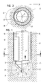
- the Erdverdrfitungsbohrer shown in Fig. 1 has a circular cylindrical Drill tube 10, welded to the lower end of a drill head 12 is.
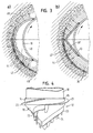
- the illustrated enlarged in Figure 4 drill head 12 has its rear end an annular shaft portion 14th on, in which the front end of the drill pipe 10 is inserted, whereupon then drill pipe 10 and drill head 12 by means of a welded joint 16 can be connected to each other.
- a cone-shaped tip section closes 18, which is formed integrally with the shaft portion 14.
- Both in the region of the shaft portion 14 as well as the tip portion 18 are provided a plurality of helical ribs 20, 21, 22 and 23, wherein the ribs 20 and 21 project radially from the shaft portion 14 and the ribs 22 and 23 in the axial direction of the tip portion 18th protrude. All of the ribs are spaced apart teeth 24 provided, which point in the axial direction of the drill head 12, with the Drilling direction X (Fig. 1) matches.
- the entire drill head 12 is integrally formed.
- the Drill head 12 as well as the drill pipe 10 are made of steel.
- the radius of the drill pipe 10 is smaller than the largest radius of the drill head 12, so that when screwing the ErdverdrDeutschungsbohrers in soil material between the resulting Drill and the drill pipe 10, an annulus 30 is formed.
- Fig. 1 illustrates Furthermore, that both the resulting in the region of the drill head 12 Borehole 32 as well as the annular channel 30 with a mixture of Drilling fluid and particles of the soil material are filled.
- the drilling fluid is via a arranged in the interior of the drill pipe 10 pipe 34th guided in the region of the foremost end of the drill head 12 and occurs from there via radial outlet channels 36 into the borehole 32.
- the leaking drilling fluid 38 mixes with particles of the soil material and fills the wellbore 32 as well as the wellbore 30.
- a mixing element 40 is provided which extends in the longitudinal direction X. of the drill pipe and the radially not over the drill head 12th protrudes, but radially outward to about the largest radius of the drill head 12 extends.
- the mixing element 40 is a groove-shaped component, whose radius is smaller than that of the drill pipe 10.
- the mixing element 40 is in the illustrated embodiment of the outer jacket the drill pipe 10 welded and at its top and bottom closed, so that between the mixing element 40 and the Drill tube 10 is enclosed a closed volume.
- Fig. 3b shows another embodiment of a mixing element 40 '.
- the mixing element 40 ' by an angular Part formed, whose two legs are the same length and enclose an angle of about 115 ° with each other.
- the position of the Mixing element 40 'on the drill pipe 10 is the same as that of the mixing element 40th
- the mixing element according to the invention either have a convex outer circumferential surface (Fig. 3a) or the mixing element may have two converging outer surfaces possess ( Figure 3b).
- the mixing element has at its Outside a surface 42 and 42 ', which is approximately tangential to the Outer jacket of the drill pipe 10 extends, and which serves as a wedge surface, there it with the wall of the drill hole 30 formed by the drill head forms a tapered region 44.
- the mixing element 40 ensures intimate mixing of drilling fluid and soil material.
- the mixing element 40 ensures that the in the annular space 30th contained mixture pressed or registered in the wall of the drill channel is, by the wedge surface 42, the mixture located in the area 44 sweeps into the wall of the Bohrkanals. This will be in the surrounding pores 46 sealed pores and the Wall of the annular space 30 and the drilling channel is plastered, so to speak and thereby sealed and stabilized.
- the Drilling channel has a stabilized wall portion 48, the same time sealed the surrounding soil, leaving the annulus above the drill head 12 is filled with drilling fluid, without this in the surrounding soil penetrates and seeps away. This is on the one hand ensures that the drill channel remains stable and does not collapse. On the other hand, it is ensured that the friction reducing effect of Drilling fluid maintained over the entire length of the drill pipe remains, which significantly increases the torque required for drilling is reduced. At the same time, the wall thickness of the drill pipe 12 within stay reasonable limits.
- the mixing element 40, 40 ' is also a certain imbalance, which imposes a certain rolling motion on the drill, which itself has a positive effect during drilling.
- the mixing element are arranged obliquely on the outer circumference of the drill pipe.
- Both drill pipe and mixing element can also be made of plastic consist.
- the mixing element can be curved in the axial direction or be formed curved. Furthermore, it is not absolutely necessary that the drilling fluid passes through the interior of the drill head into the wellbore 32 is injected. This could also be done through the annulus 30.
Landscapes
- Engineering & Computer Science (AREA)
- Mining & Mineral Resources (AREA)
- Life Sciences & Earth Sciences (AREA)
- Geology (AREA)
- General Life Sciences & Earth Sciences (AREA)
- Environmental & Geological Engineering (AREA)
- Fluid Mechanics (AREA)
- Physics & Mathematics (AREA)
- Geochemistry & Mineralogy (AREA)
- Mechanical Engineering (AREA)
- Structural Engineering (AREA)
- Paleontology (AREA)
- Civil Engineering (AREA)
- General Engineering & Computer Science (AREA)
- Earth Drilling (AREA)
- Drilling Tools (AREA)
- Processing Of Stones Or Stones Resemblance Materials (AREA)
Priority Applications (3)
| Application Number | Priority Date | Filing Date | Title |
|---|---|---|---|
| AT04003435T ATE338195T1 (de) | 2004-02-16 | 2004-02-16 | Erdverdrängungsbohrer |
| DE502004001336T DE502004001336D1 (de) | 2004-02-16 | 2004-02-16 | Erdverdrängungsbohrer |
| EP04003435A EP1564367B1 (fr) | 2004-02-16 | 2004-02-16 | Trepan de forage |
Applications Claiming Priority (1)
| Application Number | Priority Date | Filing Date | Title |
|---|---|---|---|
| EP04003435A EP1564367B1 (fr) | 2004-02-16 | 2004-02-16 | Trepan de forage |
Publications (2)
| Publication Number | Publication Date |
|---|---|
| EP1564367A1 true EP1564367A1 (fr) | 2005-08-17 |
| EP1564367B1 EP1564367B1 (fr) | 2006-08-30 |
Family
ID=34684703
Family Applications (1)
| Application Number | Title | Priority Date | Filing Date |
|---|---|---|---|
| EP04003435A Expired - Lifetime EP1564367B1 (fr) | 2004-02-16 | 2004-02-16 | Trepan de forage |
Country Status (3)
| Country | Link |
|---|---|
| EP (1) | EP1564367B1 (fr) |
| AT (1) | ATE338195T1 (fr) |
| DE (1) | DE502004001336D1 (fr) |
Cited By (2)
| Publication number | Priority date | Publication date | Assignee | Title |
|---|---|---|---|---|
| EP2011958A1 (fr) * | 2007-07-06 | 2009-01-07 | BAUER Maschinen GmbH | Tarière |
| WO2018011659A1 (fr) | 2016-07-14 | 2018-01-18 | Proferro Nv | Pointe pourvue de protubérances destinée à une opération de déplacement au sol d'un pieu de fondation |
Citations (9)
| Publication number | Priority date | Publication date | Assignee | Title |
|---|---|---|---|---|
| US3255833A (en) * | 1963-10-10 | 1966-06-14 | Texaco Development Corp | Drill bit auxiliary |
| US3799279A (en) * | 1972-09-25 | 1974-03-26 | R Farris | Optionally stabilized drilling tool |
| DE19530718C1 (de) * | 1995-08-21 | 1996-09-26 | Bauer Spezialtiefbau | Bohrvorrichtung und Verfahren zur Herstellung eines Pfahles in einem Bohrloch |
| WO1998003764A1 (fr) * | 1996-07-22 | 1998-01-29 | Gary Wayne Jarmyn | Dispositif avertisseur souterrain signalant la presence d'une canalisation ou d'une tuyauterie enterrees |
| DE19749409A1 (de) * | 1997-05-04 | 1999-05-12 | Gerd Hoermansdoerfer | Bohrverfahren und Bohrkopf |
| EP1013874A2 (fr) * | 1998-12-23 | 2000-06-28 | Ludwig Pfeiffer, Hoch- und Tiefbau GmbH & Co. KG | Dispositif et procédé pour le remplacement des tuyaux |
| DE10150278A1 (de) * | 2001-10-12 | 2003-04-30 | Tracto Technik | Verfahren und Vorrichtung zum Bodenstabilisieren |
| DE10205826A1 (de) * | 2001-10-18 | 2003-05-08 | Fitr Ges Fuer Innovation Im Ti | Verfahren zum Verlegen von Rohren mittels unterirdischem Rohrvortrieb |
| US20030141111A1 (en) * | 2000-08-01 | 2003-07-31 | Giancarlo Pia | Drilling method |
-
2004
- 2004-02-16 EP EP04003435A patent/EP1564367B1/fr not_active Expired - Lifetime
- 2004-02-16 AT AT04003435T patent/ATE338195T1/de not_active IP Right Cessation
- 2004-02-16 DE DE502004001336T patent/DE502004001336D1/de not_active Expired - Fee Related
Patent Citations (9)
| Publication number | Priority date | Publication date | Assignee | Title |
|---|---|---|---|---|
| US3255833A (en) * | 1963-10-10 | 1966-06-14 | Texaco Development Corp | Drill bit auxiliary |
| US3799279A (en) * | 1972-09-25 | 1974-03-26 | R Farris | Optionally stabilized drilling tool |
| DE19530718C1 (de) * | 1995-08-21 | 1996-09-26 | Bauer Spezialtiefbau | Bohrvorrichtung und Verfahren zur Herstellung eines Pfahles in einem Bohrloch |
| WO1998003764A1 (fr) * | 1996-07-22 | 1998-01-29 | Gary Wayne Jarmyn | Dispositif avertisseur souterrain signalant la presence d'une canalisation ou d'une tuyauterie enterrees |
| DE19749409A1 (de) * | 1997-05-04 | 1999-05-12 | Gerd Hoermansdoerfer | Bohrverfahren und Bohrkopf |
| EP1013874A2 (fr) * | 1998-12-23 | 2000-06-28 | Ludwig Pfeiffer, Hoch- und Tiefbau GmbH & Co. KG | Dispositif et procédé pour le remplacement des tuyaux |
| US20030141111A1 (en) * | 2000-08-01 | 2003-07-31 | Giancarlo Pia | Drilling method |
| DE10150278A1 (de) * | 2001-10-12 | 2003-04-30 | Tracto Technik | Verfahren und Vorrichtung zum Bodenstabilisieren |
| DE10205826A1 (de) * | 2001-10-18 | 2003-05-08 | Fitr Ges Fuer Innovation Im Ti | Verfahren zum Verlegen von Rohren mittels unterirdischem Rohrvortrieb |
Cited By (4)
| Publication number | Priority date | Publication date | Assignee | Title |
|---|---|---|---|---|
| EP2011958A1 (fr) * | 2007-07-06 | 2009-01-07 | BAUER Maschinen GmbH | Tarière |
| WO2018011659A1 (fr) | 2016-07-14 | 2018-01-18 | Proferro Nv | Pointe pourvue de protubérances destinée à une opération de déplacement au sol d'un pieu de fondation |
| US10683630B2 (en) | 2016-07-14 | 2020-06-16 | Proferro Nv | Tip with protrusions for a ground displacement operation for a foundation pile |
| EP3485096B1 (fr) * | 2016-07-14 | 2022-08-10 | Proferro NV | Pointe pourvue de protubérances destinée à une opération de déplacement au sol d'un pieu de fondation |
Also Published As
| Publication number | Publication date |
|---|---|
| ATE338195T1 (de) | 2006-09-15 |
| DE502004001336D1 (de) | 2006-10-12 |
| EP1564367B1 (fr) | 2006-08-30 |
Similar Documents
| Publication | Publication Date | Title |
|---|---|---|
| EP2257690B1 (fr) | Cheville autoforeuse protégée contre la corrosion, et bloc d'éléments de cheville, et leur procédé de fabrication | |
| DE2941769C2 (de) | Verfahren zum Setzen eines Ankerbolzens und Ankerbolzen | |
| DE10017763B4 (de) | Gebirgsanker | |
| DE3724165C2 (fr) | ||
| DE102007005540B4 (de) | Verfahren und Injektionsanker mit fixiertem Statikmischer | |
| EP0368838B1 (fr) | Dispositif de consolidation de formations géologiques non ou peu stables | |
| EP0371463A2 (fr) | Procédé pour mettre en place un ancrage et ancrage de forage d'injection de mise en oeuvre du procédé | |
| DE3738420C2 (fr) | ||
| DE3624202C2 (de) | Spiralbohrer | |
| DE102011077595A1 (de) | Ankerschraube | |
| DE3718158C2 (de) | Vorrichtung zur Erzeugung einer Hinterschneidung in einem zylindrisch vorgebohrten Bohrloch | |
| EP1564367B1 (fr) | Trepan de forage | |
| DE4024869A1 (de) | Hydraulischer selbstbohr-gesteinanker | |
| CH693934A5 (de) | Verfahren zum Bohren und Verfuellen von Loechern. | |
| DE3926787C2 (de) | Verfahren und Vorrichtung zum Einbringen und Verankern eines Zugpfahls | |
| EP3112580B1 (fr) | Procédé et dispositif pour la formation d'une canalisation souterraine | |
| DE19744322C1 (de) | Verfahren und Vorrichtung zum Einbringen von Ankern in sandigen, kiesigen oder bindigen Böden | |
| DE3737259C1 (en) | Apparatus and method for high-pressure injection | |
| DE102006023799B4 (de) | Vorrichtung zur Herstellung von Gründungselementen | |
| DE19503177C1 (de) | Verfahren zur Herstellung von Bohrpfählen | |
| DE29918581U1 (de) | Vorrichtung zum Injizieren von Dichtungsmassen | |
| EP0843073B1 (fr) | Procédé et dispositif pour la mise en place de boulons d'ancrage à injection | |
| DE10003121A1 (de) | Vorrichtung und Verfahren zur Injektion eines Injektionsmittels in den Boden | |
| DE3210696A1 (de) | Verfahren zur verankerung eines als schlaffanker dienenden rohres und rohr zur durchfuehrung des verfahrens | |
| DE10053499A1 (de) | Bohrvorrichtung |
Legal Events
| Date | Code | Title | Description |
|---|---|---|---|
| PUAI | Public reference made under article 153(3) epc to a published international application that has entered the european phase |
Free format text: ORIGINAL CODE: 0009012 |
|
| 17P | Request for examination filed |
Effective date: 20050530 |
|
| AK | Designated contracting states |
Kind code of ref document: A1 Designated state(s): AT BE BG CH CY CZ DE DK EE ES FI FR GB GR HU IE IT LI LU MC NL PT RO SE SI SK TR |
|
| AX | Request for extension of the european patent |
Extension state: AL LT LV MK |
|
| GRAP | Despatch of communication of intention to grant a patent |
Free format text: ORIGINAL CODE: EPIDOSNIGR1 |
|
| AKX | Designation fees paid |
Designated state(s): AT BE BG CH CY CZ DE DK EE ES FI FR GB GR HU IE IT LI LU MC NL PT RO SE SI SK TR |
|
| AXX | Extension fees paid |
Extension state: LT Payment date: 20050530 |
|
| GRAS | Grant fee paid |
Free format text: ORIGINAL CODE: EPIDOSNIGR3 |
|
| GRAA | (expected) grant |
Free format text: ORIGINAL CODE: 0009210 |
|
| AK | Designated contracting states |
Kind code of ref document: B1 Designated state(s): AT BE BG CH CY CZ DE DK EE ES FI FR GB GR HU IE IT LI LU MC NL PT RO SE SI SK TR |
|
| AX | Request for extension of the european patent |
Extension state: LT |
|
| PG25 | Lapsed in a contracting state [announced via postgrant information from national office to epo] |
Ref country code: GB Free format text: LAPSE BECAUSE OF FAILURE TO SUBMIT A TRANSLATION OF THE DESCRIPTION OR TO PAY THE FEE WITHIN THE PRESCRIBED TIME-LIMIT Effective date: 20060830 Ref country code: CZ Free format text: LAPSE BECAUSE OF FAILURE TO SUBMIT A TRANSLATION OF THE DESCRIPTION OR TO PAY THE FEE WITHIN THE PRESCRIBED TIME-LIMIT Effective date: 20060830 Ref country code: IE Free format text: LAPSE BECAUSE OF FAILURE TO SUBMIT A TRANSLATION OF THE DESCRIPTION OR TO PAY THE FEE WITHIN THE PRESCRIBED TIME-LIMIT Effective date: 20060830 Ref country code: SK Free format text: LAPSE BECAUSE OF FAILURE TO SUBMIT A TRANSLATION OF THE DESCRIPTION OR TO PAY THE FEE WITHIN THE PRESCRIBED TIME-LIMIT Effective date: 20060830 Ref country code: FI Free format text: LAPSE BECAUSE OF FAILURE TO SUBMIT A TRANSLATION OF THE DESCRIPTION OR TO PAY THE FEE WITHIN THE PRESCRIBED TIME-LIMIT Effective date: 20060830 Ref country code: SI Free format text: LAPSE BECAUSE OF FAILURE TO SUBMIT A TRANSLATION OF THE DESCRIPTION OR TO PAY THE FEE WITHIN THE PRESCRIBED TIME-LIMIT Effective date: 20060830 Ref country code: RO Free format text: LAPSE BECAUSE OF FAILURE TO SUBMIT A TRANSLATION OF THE DESCRIPTION OR TO PAY THE FEE WITHIN THE PRESCRIBED TIME-LIMIT Effective date: 20060830 Ref country code: IT Free format text: LAPSE BECAUSE OF FAILURE TO SUBMIT A TRANSLATION OF THE DESCRIPTION OR TO PAY THE FEE WITHIN THE PRE;WARNING: LAPSES OF ITALIAN PATENTS WITH EFFECTIVE DATE BEFORE 2007 MAY HAVE OCCURRED AT ANY TIME BEFORE 2007. THE CORRECT EFFECTIVE DATE MAY BE DIFFERENT FROM THE ONE RECORDED.SCRIBED TIME-LIMIT Effective date: 20060830 |
|
| REG | Reference to a national code |
Ref country code: GB Ref legal event code: FG4D Free format text: NOT ENGLISH |
|
| REG | Reference to a national code |
Ref country code: CH Ref legal event code: EP |
|
| REG | Reference to a national code |
Ref country code: IE Ref legal event code: FG4D Free format text: LANGUAGE OF EP DOCUMENT: GERMAN |
|
| REF | Corresponds to: |
Ref document number: 502004001336 Country of ref document: DE Date of ref document: 20061012 Kind code of ref document: P |
|
| PG25 | Lapsed in a contracting state [announced via postgrant information from national office to epo] |
Ref country code: DK Free format text: LAPSE BECAUSE OF FAILURE TO SUBMIT A TRANSLATION OF THE DESCRIPTION OR TO PAY THE FEE WITHIN THE PRESCRIBED TIME-LIMIT Effective date: 20061130 Ref country code: BG Free format text: LAPSE BECAUSE OF FAILURE TO SUBMIT A TRANSLATION OF THE DESCRIPTION OR TO PAY THE FEE WITHIN THE PRESCRIBED TIME-LIMIT Effective date: 20061130 Ref country code: SE Free format text: LAPSE BECAUSE OF FAILURE TO SUBMIT A TRANSLATION OF THE DESCRIPTION OR TO PAY THE FEE WITHIN THE PRESCRIBED TIME-LIMIT Effective date: 20061130 |
|
| PG25 | Lapsed in a contracting state [announced via postgrant information from national office to epo] |
Ref country code: ES Free format text: LAPSE BECAUSE OF FAILURE TO SUBMIT A TRANSLATION OF THE DESCRIPTION OR TO PAY THE FEE WITHIN THE PRESCRIBED TIME-LIMIT Effective date: 20061211 |
|
| PG25 | Lapsed in a contracting state [announced via postgrant information from national office to epo] |
Ref country code: PT Free format text: LAPSE BECAUSE OF FAILURE TO SUBMIT A TRANSLATION OF THE DESCRIPTION OR TO PAY THE FEE WITHIN THE PRESCRIBED TIME-LIMIT Effective date: 20070206 |
|
| LTIE | Lt: invalidation of european patent or patent extension |
Effective date: 20060830 |
|
| PG25 | Lapsed in a contracting state [announced via postgrant information from national office to epo] |
Ref country code: MC Free format text: LAPSE BECAUSE OF NON-PAYMENT OF DUE FEES Effective date: 20070228 |
|
| ET | Fr: translation filed | ||
| GBV | Gb: ep patent (uk) treated as always having been void in accordance with gb section 77(7)/1977 [no translation filed] |
Effective date: 20060830 |
|
| REG | Reference to a national code |
Ref country code: IE Ref legal event code: FD4D |
|
| PLBE | No opposition filed within time limit |
Free format text: ORIGINAL CODE: 0009261 |
|
| STAA | Information on the status of an ep patent application or granted ep patent |
Free format text: STATUS: NO OPPOSITION FILED WITHIN TIME LIMIT |
|
| 26N | No opposition filed |
Effective date: 20070531 |
|
| PG25 | Lapsed in a contracting state [announced via postgrant information from national office to epo] |
Ref country code: GR Free format text: LAPSE BECAUSE OF FAILURE TO SUBMIT A TRANSLATION OF THE DESCRIPTION OR TO PAY THE FEE WITHIN THE PRESCRIBED TIME-LIMIT Effective date: 20061201 |
|
| PGFP | Annual fee paid to national office [announced via postgrant information from national office to epo] |
Ref country code: FR Payment date: 20070212 Year of fee payment: 4 |
|
| PG25 | Lapsed in a contracting state [announced via postgrant information from national office to epo] |
Ref country code: AT Free format text: LAPSE BECAUSE OF NON-PAYMENT OF DUE FEES Effective date: 20070216 |
|
| PG25 | Lapsed in a contracting state [announced via postgrant information from national office to epo] |
Ref country code: EE Free format text: LAPSE BECAUSE OF FAILURE TO SUBMIT A TRANSLATION OF THE DESCRIPTION OR TO PAY THE FEE WITHIN THE PRESCRIBED TIME-LIMIT Effective date: 20060830 |
|
| REG | Reference to a national code |
Ref country code: FR Ref legal event code: ST Effective date: 20081031 |
|
| PG25 | Lapsed in a contracting state [announced via postgrant information from national office to epo] |
Ref country code: FR Free format text: LAPSE BECAUSE OF NON-PAYMENT OF DUE FEES Effective date: 20080229 |
|
| PG25 | Lapsed in a contracting state [announced via postgrant information from national office to epo] |
Ref country code: LU Free format text: LAPSE BECAUSE OF NON-PAYMENT OF DUE FEES Effective date: 20070216 Ref country code: CY Free format text: LAPSE BECAUSE OF FAILURE TO SUBMIT A TRANSLATION OF THE DESCRIPTION OR TO PAY THE FEE WITHIN THE PRESCRIBED TIME-LIMIT Effective date: 20060830 |
|
| PG25 | Lapsed in a contracting state [announced via postgrant information from national office to epo] |
Ref country code: HU Free format text: LAPSE BECAUSE OF FAILURE TO SUBMIT A TRANSLATION OF THE DESCRIPTION OR TO PAY THE FEE WITHIN THE PRESCRIBED TIME-LIMIT Effective date: 20070301 Ref country code: TR Free format text: LAPSE BECAUSE OF FAILURE TO SUBMIT A TRANSLATION OF THE DESCRIPTION OR TO PAY THE FEE WITHIN THE PRESCRIBED TIME-LIMIT Effective date: 20060830 |
|
| PGFP | Annual fee paid to national office [announced via postgrant information from national office to epo] |
Ref country code: CH Payment date: 20090528 Year of fee payment: 6 |
|
| PGFP | Annual fee paid to national office [announced via postgrant information from national office to epo] |
Ref country code: DE Payment date: 20090529 Year of fee payment: 6 |
|
| REG | Reference to a national code |
Ref country code: CH Ref legal event code: PL |
|
| PG25 | Lapsed in a contracting state [announced via postgrant information from national office to epo] |
Ref country code: CH Free format text: LAPSE BECAUSE OF NON-PAYMENT OF DUE FEES Effective date: 20100228 Ref country code: LI Free format text: LAPSE BECAUSE OF NON-PAYMENT OF DUE FEES Effective date: 20100228 |
|
| PG25 | Lapsed in a contracting state [announced via postgrant information from national office to epo] |
Ref country code: DE Free format text: LAPSE BECAUSE OF NON-PAYMENT OF DUE FEES Effective date: 20100901 |
|
| PGFP | Annual fee paid to national office [announced via postgrant information from national office to epo] |
Ref country code: NL Payment date: 20110216 Year of fee payment: 8 |
|
| PGFP | Annual fee paid to national office [announced via postgrant information from national office to epo] |
Ref country code: BE Payment date: 20110211 Year of fee payment: 8 |
|
| BERE | Be: lapsed |
Owner name: BEHEERSMAATSCHAPPIJ *VERSTRAETEN B.V. Effective date: 20120228 |
|
| REG | Reference to a national code |
Ref country code: NL Ref legal event code: V1 Effective date: 20120901 |
|
| PG25 | Lapsed in a contracting state [announced via postgrant information from national office to epo] |
Ref country code: BE Free format text: LAPSE BECAUSE OF NON-PAYMENT OF DUE FEES Effective date: 20120228 |
|
| PG25 | Lapsed in a contracting state [announced via postgrant information from national office to epo] |
Ref country code: NL Free format text: LAPSE BECAUSE OF NON-PAYMENT OF DUE FEES Effective date: 20120901 |