EP1564346A1 - Couverture pour un bassin tel qu'une piscine, procédé et installation pour l'assemblage d'une telle couverture - Google Patents
Couverture pour un bassin tel qu'une piscine, procédé et installation pour l'assemblage d'une telle couverture Download PDFInfo
- Publication number
- EP1564346A1 EP1564346A1 EP05364009A EP05364009A EP1564346A1 EP 1564346 A1 EP1564346 A1 EP 1564346A1 EP 05364009 A EP05364009 A EP 05364009A EP 05364009 A EP05364009 A EP 05364009A EP 1564346 A1 EP1564346 A1 EP 1564346A1
- Authority
- EP
- European Patent Office
- Prior art keywords
- cover
- profile
- slot
- groove
- bar
- Prior art date
- Legal status (The legal status is an assumption and is not a legal conclusion. Google has not performed a legal analysis and makes no representation as to the accuracy of the status listed.)
- Granted
Links
- 238000009434 installation Methods 0.000 title claims abstract description 10
- 238000000034 method Methods 0.000 title claims abstract description 8
- 230000009182 swimming Effects 0.000 title claims description 6
- 230000005489 elastic deformation Effects 0.000 claims abstract description 4
- 229920000915 polyvinyl chloride Polymers 0.000 claims description 6
- 239000004800 polyvinyl chloride Substances 0.000 claims description 6
- 229920003023 plastic Polymers 0.000 claims description 5
- 239000004033 plastic Substances 0.000 claims description 5
- XAGFODPZIPBFFR-UHFFFAOYSA-N aluminium Chemical compound [Al] XAGFODPZIPBFFR-UHFFFAOYSA-N 0.000 claims description 4
- 229910052782 aluminium Inorganic materials 0.000 claims description 4
- 230000000284 resting effect Effects 0.000 claims description 4
- 238000006073 displacement reaction Methods 0.000 claims description 3
- 208000031968 Cadaver Diseases 0.000 description 5
- 241000735470 Juncus Species 0.000 description 3
- 230000000295 complement effect Effects 0.000 description 3
- 238000005192 partition Methods 0.000 description 3
- 241000196324 Embryophyta Species 0.000 description 2
- 241001080024 Telles Species 0.000 description 2
- 230000003100 immobilizing effect Effects 0.000 description 2
- 238000004519 manufacturing process Methods 0.000 description 2
- 230000000750 progressive effect Effects 0.000 description 2
- 238000000926 separation method Methods 0.000 description 2
- 241000731961 Juncaceae Species 0.000 description 1
- 239000004411 aluminium Substances 0.000 description 1
- 230000009977 dual effect Effects 0.000 description 1
- 229940082150 encore Drugs 0.000 description 1
- 210000004197 pelvis Anatomy 0.000 description 1
- 239000007787 solid Substances 0.000 description 1
Images


Classifications
-
- E—FIXED CONSTRUCTIONS
- E04—BUILDING
- E04H—BUILDINGS OR LIKE STRUCTURES FOR PARTICULAR PURPOSES; SWIMMING OR SPLASH BATHS OR POOLS; MASTS; FENCING; TENTS OR CANOPIES, IN GENERAL
- E04H4/00—Swimming or splash baths or pools
- E04H4/06—Safety devices; Coverings for baths
- E04H4/10—Coverings of flexible material
Definitions
- the present invention relates to a cover for a pool such a swimming pool, which consists of a covering sheet attached to a series parallel and transverse stiffening bars.
- It also relates to a method and an assembly installation such coverage.
- swimming pool covers consisting of a covering tarpaulin integral with a series of parallel and transverse stiffening bars, are widespread in recent years. These are essentially requirements of security that explains this development.
- This cover consists of several elements of tarpaulin and tubular profiles.
- the transverse edges of the covering elements comprise rods or ropes able to come engage, by a sliding movement longitudinal, in additional housing provided in the profiles.
- the practice commonly used for making blankets is to use one and the same element of plastic unit covering, for example in polyvinyl chloride.
- the present invention aims to overcome these disadvantages.
- the present invention also aims at providing a method and a assembling facility such a cover easy to implement and not not requiring special skills.
- the cover when the cover is deployed on a pool such as a pool, the opposite ends of the bars resting on the edge of two sides opposite of the pelvis, and in the event that a child is on the blanket, the aforementioned ring will oppose any deformation of the pinch profile and, by consequently, to its withdrawal out of the bar.
- the cover thus preserves its integrity, without risk of disconnection of the bars and, consequently, of the child's fall in the basin.
- the invention also relates to a method of assembling such a blanket.
- a last aspect of the invention relates to an installation assembly of a cover as defined above.
- said push blade is secured to displacement means such as at least one jack.
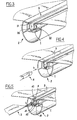
- FIGS. 1 to 6 the covering tarpaulin and one of its associated stiffening bars are shown in a returned position at 180 ° to that which they occupy when the cover is deployed on a basin.
- the covering tarpaulin 1 is of the type of the one currently used as a pool cover.
- FIG. 1 reference is made to one of the longitudinal edges of the tarpaulin 1, that is to say one of the edges which extends parallel to the direction of deployment, respectively withdrawal of the cover relative to the pool.
- this cover consists of a sheet 1 secured to a series of parallel and transverse stiffening bars 2.
- any other embodiment is conceivable, the profile being able to be solid and / or made of plastic.
- the rigidifying bar 2 has a section straight in the general shape of "C", whose opening is turned upwards.
- the bar consists of two walls 20 and 21.
- the outer wall has a shaped cross-section of "C”, while the second inner wall has a cross-section in the shape of "U”.
- 210 has been referenced the bottom of the inner wall 21, and 211, 212 its side walls that constitute the wings of the "U".
- This slot gives access to a longitudinal groove 27 delimited by the bottom 210 and wings 211 and 212 of the wall 21.
- width of the slot 26 is smaller than that of the throat 27 with which it communicates. This difference of equals is equal to width of the lip 240 added to that of the lip 250.
- the walls 24 and 25 are inclined and converge towards the slot 26.
- one of the ends of the outer wall 20 is interrupted. At this level is formed, delimited by the closing wall 25 and one radial partitions 23, a groove 29 to which there is access through a slot longitudinal 28.
- the cover according to the invention also makes use of a profile 3 in the general form of an omega ( ⁇ ), also called a pinch profile, and particularly visible in Figures 1 to 6.
- omega also called a pinch profile
- This profile is for example made of polyvinyl chloride of a few millimeters thick, which gives it a certain rigidity in the sense longitudinal. Its length is identical to that of the bar 2 with which it is intended to cooperate.
- Its body 30 here has an approximately oval shape, and is symmetrical with respect to a vertical median plane. Its open ends extend to form the legs 31 and 32 of the omega.
- the inside of the body of this profile has been referenced 33. The latter is likely to deform elastically in the direction of the arrows g of Figure 2 so as to bring the lugs 31 and 32 above. However, in the absence of such a solicitation, this profile then immediately resumes its initial shape as shown in Figure 1.
- This structure is in particular completed by a ring 4 and a skate of 5. These will be described more specifically in relation to the description of a method of assembling the cover in accordance with the invention.
- a first step is to position the cover 1 facing the slot 26 of one of the bars. We are then in the position of Figure 1. It is well understood that the longitudinal flange 10 of the tarpaulin extends perpendicular to the bar 2 shown.
- a gripping profile 3 is then grasped and introduced into the groove 27 of the bar 2, through the slot 26, in a movement generally perpendicular to the plane of the blanket, as shown by the arrow f .
- the cover 1 is driven partially inside the groove 27 by the profile 3, while the bulged portions 300 of the body 30 of the latter come to bear against the edges 240 and 250 of the slot 26. This in doing so, these bulged parts are forced to move towards one another by elastic deformation, as shown by the arrows g of FIG.
- the body 30 then fully engages in the throat 27 and resumes then its initial position as illustrated in Figure 3.
- FIG. 4 Another element of the coverage according to the invention is a rod 4 not longitudinally deformable, shown in Figures 4 and 5.
- this profile affects a section approximately triangular with a base 40 and two inclined walls 41.
- this ring is introduced inside the section 3 in a longitudinal movement illustrated by the arrow h .
- This ring has the function of opposing any deformation of the profile 3 positioned in the throat 27 and therefore, to its withdrawal out of the bar, to through slot 26 of the latter.
- the assembly thus formed is completed by a sliding shoe 5 in general shape of "T" with a foot 50 intended to engage partially inside of the body of the pinch profile 3, in the zone of separation of the tabs 31 and 33, and a small trunk 51 terminated by a large sliding surface 52 which extends to the opposite ends of the closure walls 24 and 25.
- this sliding pad is constituted several unit lengths, for example of a length of one meter, which are alternately fitted and properly positioned along the bar 2 associated. It is through this sliding pad that the cover is based on the edge of a pool.
- FIG. 6 also shows a plug 6 for closing opposite ends of the bar.
- This cap for example made of hollow plastic, is consisting in particular of a body 60 whose shape is complementary to the section the profile that constitutes the bar.
- This body is extended by a salient element 62 intended to come partially engage in the profile, in the zone separating the two partitions 22 and 23, while preventing its unexpected withdrawal.
- a through hole 61 which is intended, as shown in FIG. 7, at the passage of a cable 8 for energizing the cover, which also cooperates with hems 7 to report to the cover.
- the structure thus formed is particularly practical to square. It does not require any screw or fastener of this type, which proves very practical in terms of assembly / disassembly.
- the cover when the cover is deployed on a pool such as a pool, the opposite ends of the bars 2 resting on the edge of two opposite sides of the pond, and in the event that a child is on the covering, the ring 4 opposes any deformation of the pinch profile 3 and, by consequently, to its withdrawal out of the bar.
- the cover thus preserves its integrity, without risk of separation of the bars 2 and, consequently, of the fall of the child in the basin.
- This installation 9 comprises a support 90 of means 92 for immobilizing a rigidifying bar 2, so that the longitudinal groove 27 that it features leads to the top.
- the support 90 is surmounted by a thick plate 91, in which is formed a longitudinal channel which makes it possible to immobilize the bar 2.
- the installation also includes a push blade 932 mobile in vertical direction and disposed vertically above said groove 27, adapted to come engage in the body of the pinch profile 3 and force it to enter said throat of the bar.
- push blade is meant a longitudinal bar of limited thickness.
- the blade is secured to displacement means which, in the case shown here, consist of double-acting cylinders 93 (only one is visible at Figure 8). There are enough jacks for the length of the blade and these are controlled so that their rods 931 are moved in synchronism with respect to their bodies 930.
Landscapes
- Engineering & Computer Science (AREA)
- Architecture (AREA)
- Civil Engineering (AREA)
- Structural Engineering (AREA)
- Laminated Bodies (AREA)
- Sewage (AREA)
Abstract
- lesdites barres rigidificatrices (2) comportent une gorge longitudinale (27) qui débouche à l'extérieur par une fente (26);
- la bâche (1) est partiellement introduite dans la gorge (27) et pincée entre celle-ci et un profilé (3) en forme générale de oméga -dit profilé de pincement - dont le corps (30), prévu élastiquement déformable, est dimensionné pour occuper, au repos, au moins en partie l'espace interne de ladite gorge (27), ses pattes (31, 32) s'appuyant alors sur la face externe des rebords (240, 250) de la fente (26),
Description
- lesdites barres rigidificatrices comportent une gorge longitudinale qui débouche à l'extérieur par une fente ;
- la bâche est partiellement introduite dans la gorge et pincée entre le fond de celle-ci et un profilé en forme générale de oméga -dit profilé de pincement - dont le corps, prévu élastiquement déformable, est dimensionné pour occuper, au repos, au moins en partie l'espace interne de ladite gorge, ses pattes s'appuyant alors sur la face externe des rebords de la fente,
- ledit profilé de pincement est conformé de manière à permettre la déformation du corps par rapprochement de ses pattes l'une de l'autre ;
- ledit profilé est en matière plastique, notamment en chlorure de polyvinyle ;
- lesdites barres rigidificatrices consistent en des profilés creux, par exemple en aluminium extrudé ;
- lesdites barres rigidificatrices ont une section droite en forme générale de "C" ;
- lesdites barres rigidificatrices sont pourvues d'un patin de glissement, par exemple engagé entre les pattes du profilé de pincement ;
- ledit patin est constitué de plusieurs tronçons contigus ;
- les extrémités opposés desdites barres sont chacune pourvues d'un bouchon d'obturation.
- on positionne ladite couverture face à la fente d'une des dites barres ;
- on introduit ledit profilé de pincement dans ladite gorge, au travers de ladite fente, selon un mouvement généralement perpendiculaire au plan de la couverture, jusqu'à ce que ses pattes s'appuient sur les rebords de la fente ;
- on introduit ledit jonc dans le corps dudit profilé selon une direction parallèle à ce dernier,
- on réitère les opérations précédentes pour chaque barre.
- des moyens pour immobiliser une barre rigidificatrice de telle sorte que la gorge longitudinale qu'elle comporte débouche vers le haut ;
- une lame poussoir mobile en direction verticale et disposée à l'aplomb de ladite gorge, adaptée pour venir s'engager dans le corps du profilé de pincement et forcer celui-ci à pénétrer dans ladite gorge de la barre.
- les figures 1 à 3 sont des vues partielles en perspective d'une bâche, d'une barre rigidificatrice et d'un profilé de pincement, montrant les étapes progressives d'engagement du profilé dans la barre et de pincement résultant de la bâche ;
- les figures 4 et 5 sont des vues analogues aux précédentes, destinées respectivement à illustrer la mise en place d'un jonc de maintien et d'un patin de glissement ;
- la figure 6 est encore une figure analogue aux précédentes, destinée à illustrer la mise en place d'un bouchon d'obturation à une des extrémités d'une barre rigidificatrice ;
- la figure 7 est une vue partielle en perspective et en contre plongée d'une couverture ainsi équipée ;
- la figure 8 est une vue simplifiée de face d'une installation d'assemblage d'une telle couverture.
Claims (11)
- Couverture pour un bassin tel qu'une piscine, qui est constituée d'une bâche de recouvrement (1) solidaire d'une série de barres rigidificatrices (2) parallèles et transversales, caractérisée par le fait que :et qu'elle comporte un jonc de maintien non déformable (4) qui occupe au moins en partie l'intérieur (33) du corps (30) du profilé de pincement (3) et qui s'oppose à toute déformation de ce dernier et, par conséquent à son retrait hors de la barre (2) à travers ladite fente (26), par déformation élastique.lesdites barres rigidificatrices (2) comportent une gorge longitudinale (27) qui débouche à l'extérieur par une fente (26) ;la bâche (1) est partiellement introduite dans la gorge (27) et pincée entre celle-ci et un profilé (3) en forme générale de oméga -dit profilé de pincement - dont le corps (30), prévu élastiquement déformable, est dimensionné pour occuper, au repos, au moins en partie l'espace interne de ladite gorge (27), ses pattes (31, 32) s'appuyant alors sur la face externe des rebords (240,250) de la fente (26),
- Couverture selon la revendication 1, caractérisée par le fait que ledit profilé de pincement (3) est conformé de manière à permettre la déformation du corps (30) par rapprochement de ses pattes (31, 33) l'une de l'autre.
- Couverture selon l'une des revendications 1 ou 2, caractérisée par le fait que ledit profilé (3) est en matière plastique, notamment en chlorure de polyvinyle.
- Couverture selon l'une des revendications précédentes, caractérisée par le fait que lesdites barres rigidificatrices (2) consistent en des profilés creux, par exemple en aluminium extrudé.
- Couverture selon l'une des revendications précédentes, caractérisée par le fait que lesdites barres rigidificatrices (2) ont une section droite en forme générale de "C".
- Couverture selon l'une des revendications précédentes, caractérisée par le fait que lesdites barres rigidificatrices (2) sont pourvues d'un patin de glissement (5), par exemple engagé entre les pattes (30,31) du profilé de pincement (3).
- Couverture selon la revendication 6, caractérisée par le fait que ledit patin (5) est constitué de plusieurs tronçons contigus.
- Couverture selon l'une des revendications précédentes, caractérisée par le fait que les extrémités opposés desdites barres (2) sont chacune pourvue d'un bouchon d'obturation (6).
- Procédé d'assemblage d'une couverture selon l'une des revendications 1 à 8, caractérisé par le fait qu'il comprend notamment les étapes successives suivantes :on positionne ladite bâche (1) face à la fente (26) d'une des dites barres (2) ;on introduit ledit profilé de pincement (3) dans ladite gorge (27), au travers de ladite fente (26), selon un mouvement généralement perpendiculaire au plan de la couverture, jusqu'à ce que ses pattes (30,31) s'appuient sur les rebords (240, 250) de la fente ;on introduit ledit jonc (4) dans le corps (30) dudit profilé (3) selon une direction parallèle à ce dernier,on réitère les opérations précédentes pour chaque barre (2).
- Installation d'assemblage d'une couverture selon l'une des revendications 1 à 8, caractérisée par le fait qu'elle comporte :des moyens (92) pour immobiliser une barre rigidificatrice (2) de telle sorte que la gorge longitudinale (27) qu'elle comporte débouche vers le haut ;une lame poussoir (932) mobile en direction verticale et disposée à l'aplomb de ladite gorge (27), adaptée pour venir s'engager dans le corps (30) du profilé (3) de pincement et forcer celui-ci à pénétrer dans ladite gorge (27) de la barre (1).
- Installation selon la revendication précédente, caractérisée par le fait que ladite lame poussoir (932) est solidaire de moyens de déplacement (93) tels qu'au moins un vérin.
Applications Claiming Priority (2)
| Application Number | Priority Date | Filing Date | Title |
|---|---|---|---|
| FR0401460A FR2866383B1 (fr) | 2004-02-13 | 2004-02-13 | Couverture pour un bassin tel qu'une piscine, procede et installation pour l'assemblage d'une telle couverture. |
| FR0401460 | 2004-02-13 |
Publications (2)
| Publication Number | Publication Date |
|---|---|
| EP1564346A1 true EP1564346A1 (fr) | 2005-08-17 |
| EP1564346B1 EP1564346B1 (fr) | 2007-04-11 |
Family
ID=34685021
Family Applications (1)
| Application Number | Title | Priority Date | Filing Date |
|---|---|---|---|
| EP20050364009 Expired - Lifetime EP1564346B1 (fr) | 2004-02-13 | 2005-02-03 | Couverture pour un bassin tel qu'une piscine, procédé et installation pour l'assemblage d'une telle couverture |
Country Status (3)
| Country | Link |
|---|---|
| EP (1) | EP1564346B1 (fr) |
| DE (1) | DE602005000824D1 (fr) |
| FR (1) | FR2866383B1 (fr) |
Cited By (1)
| Publication number | Priority date | Publication date | Assignee | Title |
|---|---|---|---|---|
| EP2116671A1 (fr) * | 2008-05-06 | 2009-11-11 | Bieri Alpha Covers AG | barre pour une couverture de piscine |
Citations (2)
| Publication number | Priority date | Publication date | Assignee | Title |
|---|---|---|---|---|
| US5107552A (en) * | 1990-05-03 | 1992-04-28 | Vogue Industries, Ltd. | Swimming pool cover and roll-up device |
| EP0570311A1 (fr) * | 1992-05-11 | 1993-11-18 | Etablissements Lucien WALTER Société Anonyme dite, | Dispositif de recouvrement d'un bassin tel qu'une piscine |
-
2004
- 2004-02-13 FR FR0401460A patent/FR2866383B1/fr not_active Expired - Lifetime
-
2005
- 2005-02-03 DE DE200560000824 patent/DE602005000824D1/de not_active Expired - Lifetime
- 2005-02-03 EP EP20050364009 patent/EP1564346B1/fr not_active Expired - Lifetime
Patent Citations (2)
| Publication number | Priority date | Publication date | Assignee | Title |
|---|---|---|---|---|
| US5107552A (en) * | 1990-05-03 | 1992-04-28 | Vogue Industries, Ltd. | Swimming pool cover and roll-up device |
| EP0570311A1 (fr) * | 1992-05-11 | 1993-11-18 | Etablissements Lucien WALTER Société Anonyme dite, | Dispositif de recouvrement d'un bassin tel qu'une piscine |
Cited By (1)
| Publication number | Priority date | Publication date | Assignee | Title |
|---|---|---|---|---|
| EP2116671A1 (fr) * | 2008-05-06 | 2009-11-11 | Bieri Alpha Covers AG | barre pour une couverture de piscine |
Also Published As
| Publication number | Publication date |
|---|---|
| FR2866383B1 (fr) | 2006-05-19 |
| DE602005000824D1 (de) | 2007-05-24 |
| FR2866383A1 (fr) | 2005-08-19 |
| EP1564346B1 (fr) | 2007-04-11 |
Similar Documents
| Publication | Publication Date | Title |
|---|---|---|
| EP0224290B1 (fr) | Structure de couverture découvrable | |
| EP1841929B1 (fr) | Ensemble d'elements pour l'obtention d'un panneau | |
| EP2882056B1 (fr) | Cadre de montage pour l'encastrement d'une boîte électrique dans une paroi et ensemble comprenant un tel cadre de montage et une boîte électrique | |
| EP0294301B1 (fr) | Dispositif de solidarisation temporaire des extrémités de deux structures dont au moins une est souple | |
| EP2406093B1 (fr) | Profile pour element de fermeture de benne de vehicule et element de fermeture correspondant | |
| EP1564346B1 (fr) | Couverture pour un bassin tel qu'une piscine, procédé et installation pour l'assemblage d'une telle couverture | |
| EP1309409B1 (fr) | Organe de fixation pour un distributeur | |
| FR2975717A1 (fr) | Insert dissociable de blocage vertical entre deux lames d'une structure plane de parement ou de parquet. | |
| WO2012140329A1 (fr) | Dispositif de formation d'une réservation au sein d'un élément de construction accueillant une ancre de manutention, adaptable aux dimensions de l'ancre | |
| FR2765606A1 (fr) | Poutrelle de support pour un caillebotis de piscine enterree | |
| EP1707706B1 (fr) | Pièce à bancher un élément d'ouvrage tel que des marches d'un escalier, en particulier pour une piscine | |
| FR2701527A1 (fr) | Joint d'étanchéité, notamment destiné à établir une étanchéité entre deux tuyaux ou analogues mutuellement emboîtés, et tuyau ou analogue comportant un tel joint. | |
| FR3062865A1 (fr) | Procede de montage d'un revetement souple tendu sur un cadre de fixation et cadre de fixation pour la mise en oeuvre dudit procede | |
| EP0943043B1 (fr) | Element de paroi a courbure variable pour piscine | |
| EP1132290B1 (fr) | Panneau d'écoutille | |
| EP3043003B1 (fr) | Lisse pour la réalisationd'un cadre de dalle pour fausse paroi comportant des zones pleines définissant des zones de renfort | |
| EP2808465B1 (fr) | Structure pour bassin et couverture | |
| FR2684712A1 (fr) | Dispositif de liaison etanche pour abris legers modulaires. | |
| FR2946557A1 (fr) | Procede de mise en place d'un joint souple filant dans une rainure de profile, et outil permettant une mise en oeuvre du procede | |
| FR2952950A1 (fr) | Panneau a lames, cloture formee a partir d'un assemblage desdits panneaux et lame pour la realisation d'un tel panneau | |
| BE1023928B1 (fr) | Lame de volet roulant avec profils d'accrochage à butée partielle, Volet roulant, notamment de recouvrement de piscine, et Procédé d'assemblage correspondant | |
| FR3138278A1 (fr) | Dispositif annulaire pour œillet ou anneau de rideau | |
| FR2729985A1 (fr) | Structure d'installation generale a mise en place de panneaux de cloison facilitee | |
| EP1371784A1 (fr) | Coffrage en particulier pour la fabrication de massif en béton | |
| FR2908429A1 (fr) | Structure modulaire pour la realisation de paroi subissant en service des poussees horizontales, notamment paroi peripherique de bassin |
Legal Events
| Date | Code | Title | Description |
|---|---|---|---|
| PUAI | Public reference made under article 153(3) epc to a published international application that has entered the european phase |
Free format text: ORIGINAL CODE: 0009012 |
|
| AK | Designated contracting states |
Kind code of ref document: A1 Designated state(s): AT BE BG CH CY CZ DE DK EE ES FI FR GB GR HU IE IS IT LI LT LU MC NL PL PT RO SE SI SK TR |
|
| AX | Request for extension of the european patent |
Extension state: AL BA HR LV MK YU |
|
| 17P | Request for examination filed |
Effective date: 20050920 |
|
| AKX | Designation fees paid |
Designated state(s): BE CH DE ES FR LI |
|
| GRAP | Despatch of communication of intention to grant a patent |
Free format text: ORIGINAL CODE: EPIDOSNIGR1 |
|
| GRAS | Grant fee paid |
Free format text: ORIGINAL CODE: EPIDOSNIGR3 |
|
| GRAA | (expected) grant |
Free format text: ORIGINAL CODE: 0009210 |
|
| AK | Designated contracting states |
Kind code of ref document: B1 Designated state(s): BE CH DE ES FR LI |
|
| REG | Reference to a national code |
Ref country code: CH Ref legal event code: EP |
|
| REF | Corresponds to: |
Ref document number: 602005000824 Country of ref document: DE Date of ref document: 20070524 Kind code of ref document: P |
|
| PG25 | Lapsed in a contracting state [announced via postgrant information from national office to epo] |
Ref country code: ES Free format text: LAPSE BECAUSE OF FAILURE TO SUBMIT A TRANSLATION OF THE DESCRIPTION OR TO PAY THE FEE WITHIN THE PRESCRIBED TIME-LIMIT Effective date: 20070722 |
|
| PLBE | No opposition filed within time limit |
Free format text: ORIGINAL CODE: 0009261 |
|
| REG | Reference to a national code |
Ref country code: CH Ref legal event code: NV Representative=s name: MICHELI & CIE SA |
|
| STAA | Information on the status of an ep patent application or granted ep patent |
Free format text: STATUS: NO OPPOSITION FILED WITHIN TIME LIMIT |
|
| 26N | No opposition filed |
Effective date: 20080114 |
|
| PG25 | Lapsed in a contracting state [announced via postgrant information from national office to epo] |
Ref country code: DE Free format text: LAPSE BECAUSE OF FAILURE TO SUBMIT A TRANSLATION OF THE DESCRIPTION OR TO PAY THE FEE WITHIN THE PRESCRIBED TIME-LIMIT Effective date: 20070712 |
|
| PG25 | Lapsed in a contracting state [announced via postgrant information from national office to epo] |
Ref country code: BE Free format text: LAPSE BECAUSE OF NON-PAYMENT OF DUE FEES Effective date: 20150228 |
|
| REG | Reference to a national code |
Ref country code: FR Ref legal event code: PLFP Year of fee payment: 12 |
|
| PGFP | Annual fee paid to national office [announced via postgrant information from national office to epo] |
Ref country code: CH Payment date: 20160208 Year of fee payment: 12 |
|
| REG | Reference to a national code |
Ref country code: FR Ref legal event code: PLFP Year of fee payment: 13 |
|
| REG | Reference to a national code |
Ref country code: CH Ref legal event code: PL |
|
| PG25 | Lapsed in a contracting state [announced via postgrant information from national office to epo] |
Ref country code: LI Free format text: LAPSE BECAUSE OF NON-PAYMENT OF DUE FEES Effective date: 20170228 Ref country code: CH Free format text: LAPSE BECAUSE OF NON-PAYMENT OF DUE FEES Effective date: 20170228 |
|
| REG | Reference to a national code |
Ref country code: FR Ref legal event code: PLFP Year of fee payment: 14 |
|
| PGFP | Annual fee paid to national office [announced via postgrant information from national office to epo] |
Ref country code: FR Payment date: 20230113 Year of fee payment: 19 |
|
| PGFP | Annual fee paid to national office [announced via postgrant information from national office to epo] |
Ref country code: BE Payment date: 20230220 Year of fee payment: 19 |
|
| REG | Reference to a national code |
Ref country code: BE Ref legal event code: MM Effective date: 20240229 |
|
| PG25 | Lapsed in a contracting state [announced via postgrant information from national office to epo] |
Ref country code: BE Free format text: LAPSE BECAUSE OF NON-PAYMENT OF DUE FEES Effective date: 20240229 |
|
| PG25 | Lapsed in a contracting state [announced via postgrant information from national office to epo] |
Ref country code: FR Free format text: LAPSE BECAUSE OF NON-PAYMENT OF DUE FEES Effective date: 20240229 |
|
| PG25 | Lapsed in a contracting state [announced via postgrant information from national office to epo] |
Ref country code: FR Free format text: LAPSE BECAUSE OF NON-PAYMENT OF DUE FEES Effective date: 20240229 Ref country code: BE Free format text: LAPSE BECAUSE OF NON-PAYMENT OF DUE FEES Effective date: 20240229 |