EP1564166B1 - Support for a roll of a belt conveyor - Google Patents
Support for a roll of a belt conveyor Download PDFInfo
- Publication number
- EP1564166B1 EP1564166B1 EP04350001A EP04350001A EP1564166B1 EP 1564166 B1 EP1564166 B1 EP 1564166B1 EP 04350001 A EP04350001 A EP 04350001A EP 04350001 A EP04350001 A EP 04350001A EP 1564166 B1 EP1564166 B1 EP 1564166B1
- Authority
- EP
- European Patent Office
- Prior art keywords
- roller
- support
- retaining device
- conveyor
- roll
- Prior art date
- Legal status (The legal status is an assumption and is not a legal conclusion. Google has not performed a legal analysis and makes no representation as to the accuracy of the status listed.)
- Expired - Lifetime
Links
Images
Classifications
-
- A—HUMAN NECESSITIES
- A61—MEDICAL OR VETERINARY SCIENCE; HYGIENE
- A61H—PHYSICAL THERAPY APPARATUS, e.g. DEVICES FOR LOCATING OR STIMULATING REFLEX POINTS IN THE BODY; ARTIFICIAL RESPIRATION; MASSAGE; BATHING DEVICES FOR SPECIAL THERAPEUTIC OR HYGIENIC PURPOSES OR SPECIFIC PARTS OF THE BODY
- A61H39/00—Devices for locating or stimulating specific reflex points of the body for physical therapy, e.g. acupuncture
- A61H39/04—Devices for pressing such points, e.g. Shiatsu or Acupressure
-
- B—PERFORMING OPERATIONS; TRANSPORTING
- B65—CONVEYING; PACKING; STORING; HANDLING THIN OR FILAMENTARY MATERIAL
- B65G—TRANSPORT OR STORAGE DEVICES, e.g. CONVEYORS FOR LOADING OR TIPPING, SHOP CONVEYOR SYSTEMS OR PNEUMATIC TUBE CONVEYORS
- B65G15/00—Conveyors having endless load-conveying surfaces, i.e. belts and like continuous members, to which tractive effort is transmitted by means other than endless driving elements of similar configuration
-
- A—HUMAN NECESSITIES
- A43—FOOTWEAR
- A43B—CHARACTERISTIC FEATURES OF FOOTWEAR; PARTS OF FOOTWEAR
- A43B7/00—Footwear with health or hygienic arrangements
- A43B7/14—Footwear with health or hygienic arrangements with foot-supporting parts
- A43B7/1405—Footwear with health or hygienic arrangements with foot-supporting parts with pads or holes on one or more locations, or having an anatomical or curved form
- A43B7/1455—Footwear with health or hygienic arrangements with foot-supporting parts with pads or holes on one or more locations, or having an anatomical or curved form with special properties
- A43B7/146—Footwear with health or hygienic arrangements with foot-supporting parts with pads or holes on one or more locations, or having an anatomical or curved form with special properties provided with acupressure points or means for foot massage
-
- A—HUMAN NECESSITIES
- A43—FOOTWEAR
- A43B—CHARACTERISTIC FEATURES OF FOOTWEAR; PARTS OF FOOTWEAR
- A43B7/00—Footwear with health or hygienic arrangements
- A43B7/32—Footwear with health or hygienic arrangements with shock-absorbing means
-
- A—HUMAN NECESSITIES
- A47—FURNITURE; DOMESTIC ARTICLES OR APPLIANCES; COFFEE MILLS; SPICE MILLS; SUCTION CLEANERS IN GENERAL
- A47K—SANITARY EQUIPMENT; ACCESSORIES THEREFOR, e.g. TOILET ACCESSORIES
- A47K3/00—Baths; Showers; Appurtenances therefor
- A47K3/12—Separate seats or body supports
-
- B—PERFORMING OPERATIONS; TRANSPORTING
- B65—CONVEYING; PACKING; STORING; HANDLING THIN OR FILAMENTARY MATERIAL
- B65G—TRANSPORT OR STORAGE DEVICES, e.g. CONVEYORS FOR LOADING OR TIPPING, SHOP CONVEYOR SYSTEMS OR PNEUMATIC TUBE CONVEYORS
- B65G15/00—Conveyors having endless load-conveying surfaces, i.e. belts and like continuous members, to which tractive effort is transmitted by means other than endless driving elements of similar configuration
- B65G15/60—Arrangements for supporting or guiding belts, e.g. by fluid jets
- B65G15/62—Guides for sliding belts
-
- B—PERFORMING OPERATIONS; TRANSPORTING
- B65—CONVEYING; PACKING; STORING; HANDLING THIN OR FILAMENTARY MATERIAL
- B65G—TRANSPORT OR STORAGE DEVICES, e.g. CONVEYORS FOR LOADING OR TIPPING, SHOP CONVEYOR SYSTEMS OR PNEUMATIC TUBE CONVEYORS
- B65G21/00—Supporting or protective framework or housings for endless load-carriers or traction elements of belt or chain conveyors
- B65G21/20—Means incorporated in, or attached to, framework or housings for guiding load-carriers, traction elements or loads supported on moving surfaces
- B65G21/2045—Mechanical means for guiding or retaining the load on the load-carrying surface
- B65G21/2063—Mechanical means for guiding or retaining the load on the load-carrying surface comprising elements not movable in the direction of load-transport
- B65G21/2072—Laterial guidance means
- B65G21/2081—Laterial guidance means for bulk material, e.g. skirts
-
- A—HUMAN NECESSITIES
- A61—MEDICAL OR VETERINARY SCIENCE; HYGIENE
- A61H—PHYSICAL THERAPY APPARATUS, e.g. DEVICES FOR LOCATING OR STIMULATING REFLEX POINTS IN THE BODY; ARTIFICIAL RESPIRATION; MASSAGE; BATHING DEVICES FOR SPECIAL THERAPEUTIC OR HYGIENIC PURPOSES OR SPECIFIC PARTS OF THE BODY
- A61H2201/00—Characteristics of apparatus not provided for in the preceding codes
- A61H2201/01—Constructive details
- A61H2201/0119—Support for the device
-
- A—HUMAN NECESSITIES
- A61—MEDICAL OR VETERINARY SCIENCE; HYGIENE
- A61H—PHYSICAL THERAPY APPARATUS, e.g. DEVICES FOR LOCATING OR STIMULATING REFLEX POINTS IN THE BODY; ARTIFICIAL RESPIRATION; MASSAGE; BATHING DEVICES FOR SPECIAL THERAPEUTIC OR HYGIENIC PURPOSES OR SPECIFIC PARTS OF THE BODY
- A61H2201/00—Characteristics of apparatus not provided for in the preceding codes
- A61H2201/16—Physical interface with patient
- A61H2201/1683—Surface of interface
- A61H2201/169—Physical characteristics of the surface, e.g. material, relief, texture or indicia
- A61H2201/1695—Enhanced pressure effect, e.g. substantially sharp projections, needles or pyramids
-
- A—HUMAN NECESSITIES
- A61—MEDICAL OR VETERINARY SCIENCE; HYGIENE
- A61H—PHYSICAL THERAPY APPARATUS, e.g. DEVICES FOR LOCATING OR STIMULATING REFLEX POINTS IN THE BODY; ARTIFICIAL RESPIRATION; MASSAGE; BATHING DEVICES FOR SPECIAL THERAPEUTIC OR HYGIENIC PURPOSES OR SPECIFIC PARTS OF THE BODY
- A61H2205/00—Devices for specific parts of the body
- A61H2205/12—Feet
- A61H2205/125—Foot reflex zones
Definitions
- the invention relates to a holding device for a conveyor belt roller or carrier slats. It also relates to the conveyor equipped with said device.
- the transfer of products can be achieved with different devices whose choice depends on different parameters such as the distance of transport, the volume to be transported per unit of time, etc.
- a belt conveyor comprises an endless belt carried by a succession of rollers supported by a frame.
- the active part of the band must be shaped V or U to form a kind of trough or trough containing the product along its path.
- the band runs on sets of carrier rollers distributed along the path and transversely to said path.
- the geometric position of a set defines the concavity of the band and therefore the desired generator.
- a horizontal central roller and two or more lateral rollers inclined relative to the horizontal are used to raise the edges of the endless belt.
- the invention proposes to provide a solution to the problems mentioned above.
- a holding device for a conveyor roll is provided as defined in claim 1.
- the invention also relates to the conveyor equipped with said holding device.
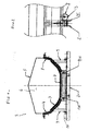
- the guide surface is for example made by a roller 7.
- FIG 1 it is mounted above the belt or endless surface 3, a cover 5, optionally on articulation, to form a closed volume 6.
- the edges of the endless bearing surface 3 must be raised to form a channel intended to contain the bulk material deposited on this conveyor.
- Known tensioners and motor means ensure the movement of the endless belt.
- the transported material moves in an open tunnel at both ends.
- the curvature of the web in the transverse axis or the generator is defined by a horizontal roller 7 and two curved lateral surfaces 8 located on either side of the aforementioned roller or other rollers.
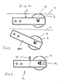
- the horizontal roller 7 is mounted on a tilting support 13 for quick release to change it.
- This support comprises, for example, two cheeks 13A each having a notch 14 for sliding the axis of rotation of the horizontal roller.
- the notches 14 are provided to engage the roller axis from above.
- This roller 7 is not likely to come out of these cuts.
- the cuts 14 could lead to the front or the bottom.
- the cross-member carrying the roll has a point-in-point protection device.
- the support carries the protection device 15 point re-entrant limiting the risk that a garment is caught by the roller and the band.
- This technical aspect works on any belt conveyor extending in a substantially horizontal plane or a curved plane.
- each lateral surface extends laterally beyond the surface on which the endless belt is supported. At least locally, at least one of the lateral surfaces 8 is fixed to the frame by means 9 for quick attachment to form a sort of access door quickly clearing an opening.
- the lateral surface 8 therefore has an endless belt guiding function and an access hatch function.
- the lateral surface presented by the side wall is continuous. While interruptions may be expected, they minimize the effectiveness of containment.
- a closed tube is reconstituted, however, including an opening at the base. This opening is located at the location of the horizontal rollers distributed along the path.
- the removable lateral surface 8 is preferably carried by guide means 10 for moving it between two positions defined in advance.
- a lock will be performed by a simple lock to enable or disable.
- These guide means 10 are, in a first embodiment, capable of performing a guide in translation, for example by means of at least one slide and its slide.
- each side wall element 8 is fixed by at least one hinge so as to obtain a tilting or a rotation about an axis defined during assembly.
- the shape is represented on an axis hinge parallel to the axis of movement of the endless belt.
- the hinge is placed at the base of the side wall.
- This hinge could be vertical axis, each side wall behaving like a hinged door.
- This aspect makes it very easy to move a portion of the side wall of the conveyor to access the interior of the containment tube of the material.
- the lateral surfaces 8 will be removable in all points.
- the active face of the lateral surface 8 consists of at least two planes or two curves forming between them a break 12 to block the band in its lateral displacement.
- the band does not hold rigorously in the axis of movement but moves laterally.
- the edge of the band hits the break, the effort to go beyond this break to increase, the band goes in the other direction by a reaction phenomenon.
- the side walls are made, for example steel.
- At least the active surface of the lateral surface has a low roughness.
- a layer of a material facilitating sliding can cover the side surface.
- the hood is raised to increase the volume of the tube and limit the overpressure.
- the free edge 8A of the side wall having the lateral surface is secured to the hood by a removable fastening means such as a latch
- the tilting holding device is guided in rotation about an axis and a latch made for example by a bolt locks the tilting support in active position of the roller resting on the band.
Landscapes
- Health & Medical Sciences (AREA)
- Mechanical Engineering (AREA)
- Engineering & Computer Science (AREA)
- Public Health (AREA)
- General Health & Medical Sciences (AREA)
- Epidemiology (AREA)
- Rehabilitation Therapy (AREA)
- Life Sciences & Earth Sciences (AREA)
- Veterinary Medicine (AREA)
- Physical Education & Sports Medicine (AREA)
- Pain & Pain Management (AREA)
- Animal Behavior & Ethology (AREA)
- Structure Of Belt Conveyors (AREA)
- Rollers For Roller Conveyors For Transfer (AREA)
- Rolls And Other Rotary Bodies (AREA)
- Crushing And Grinding (AREA)
- Sewing Machines And Sewing (AREA)
- Delivering By Means Of Belts And Rollers (AREA)
- Massaging Devices (AREA)
- Spinning Or Twisting Of Yarns (AREA)
- Belt Conveyors (AREA)
Abstract
Description
L'invention se rapporte à un dispositif de maintien pour un rouleau de convoyeur à bande ou à tasseaux porteurs. Elle se rapporte également au convoyeur équipé dudit dispositif.The invention relates to a holding device for a conveyor belt roller or carrier slats. It also relates to the conveyor equipped with said device.
Le transfert de produits, notamment en vrac d'un endroit vers un autre, peut être réalisé avec différents appareils dont le choix dépend de différents paramètres tels que la distance du transport, le volume à transporter par unité de temps, etc.The transfer of products, especially in bulk from one place to another, can be achieved with different devices whose choice depends on different parameters such as the distance of transport, the volume to be transported per unit of time, etc.
Classiquement un convoyeur à bande comprend une bande sans fin portée par une succession de rouleaux supportés par un châssis.Conventionally a belt conveyor comprises an endless belt carried by a succession of rollers supported by a frame.
Lorsque ces convoyeurs à bande sans fin transportent des produits en vrac, la partie active de la bande doit être conformée en V ou en U afin de constituer une sorte de rigole ou auge contenant le produit tout au long de son parcours.When these conveyors endless belt convey bulk products, the active part of the band must be shaped V or U to form a kind of trough or trough containing the product along its path.
Couramment, pour obtenir cette forme en V ou en U, la bande circule sur des ensembles de rouleaux porteurs répartis le long du parcours et transversalement au dit parcours.Commonly, to obtain this V-shaped or U-shaped, the band runs on sets of carrier rollers distributed along the path and transversely to said path.
La position géométrique d'un ensemble définit la concavité de la bande et donc la génératrice souhaitée.The geometric position of a set defines the concavity of the band and therefore the desired generator.
Généralement, pour cet ensemble de guidage, on fait appel à un rouleau central horizontal et à deux ou plusieurs rouleaux latéraux inclinés par rapport à l'horizontal pour relever les bords de la bande sans fin.Generally, for this guide assembly, a horizontal central roller and two or more lateral rollers inclined relative to the horizontal are used to raise the edges of the endless belt.
L'accès aux différents rouleaux n'est pas aisé et dans le cas de matériaux pondéreux, la présence de poussières accroît nécessairement les opérations de maintien.Access to the different rolls is not easy and in the case of heavy materials, the presence of dust necessarily increases the maintenance operations.
Ces arrêts sont très longs car il faut démonter les pattes qui maintiennent l'axe du rouleau pour pouvoir dégager le rouleau (voire par exemple US 2695701).These stops are very long because it is necessary to disassemble the tabs that hold the axis of the roller to be able to clear the roll (see for example US 2695701).
L'invention se propose d'apporter une solution aux problèmes évoqués notamment ci dessus.The invention proposes to provide a solution to the problems mentioned above.
A cet effet, un dispositif de maintien pour un rouleau de convoyeur est prévu tel que défini dans la revendication 1.For this purpose, a holding device for a conveyor roll is provided as defined in
L'invention se rapporte également au convoyeur équipé dudit dispositif de maintien.The invention also relates to the conveyor equipped with said holding device.
L'invention sera bien comprise à l'aide de la description ci-après faite à titre d'exemple non limitatif en regard du dessin qui représente schématiquement :
- FIG 1 : Vue en coupe transversale d'un exemple de convoyeur.
- FIG 2 : Vue latérale de la figure 1
- FIG 3 : Vue d'un dispositif de maintien d'un rouleau en position active.
- FIG 4 : Vue d'un dispositif de maintien d'un rouleau en position inactive.
- FIG 5 : Une variante d'un dispositif de maintien d'un rouleau.
- FIG. 1: Cross-sectional view of an example of a conveyor.
- FIG 2: Side view of FIG. 1
- FIG 3: View of a device for holding a roller in the active position.
- FIG 4: View of a device for holding a roll in the inactive position.
- FIG. 5: A variant of a device for holding a roll.
En se reportant au dessin on voit un convoyeur 1 à bande ou à tasseaux porteurs. Classiquement un convoyeur 1 comprend :
- portée par un
châssis 2, unesurface 3 sans fin portante se déplaçant sur unesurface 4 de guidage définissant une génératrice, par exemple, courbe.
- carried by a
frame 2, a bearingendless surface 3 moving on aguide surface 4 defining a generator, for example, curved.
La surface de guidage est par exemple réalisée par un rouleau 7.The guide surface is for example made by a
Dans l'exemple représenté FIG 1, il est monté au dessus de la bande ou surface 3 sans fin, un capot 5, éventuellement sur articulation, pour constituer un volume 6 clos.In the example shown in FIG 1, it is mounted above the belt or
Les bords de la surface 3 sans fin portante doivent être relevés pour former une rigole destinée à contenir le matériau en vrac déposé sur ce convoyeur.The edges of the endless bearing
Des tendeurs et moyens moteurs connus assurent le déplacement de la bande sans fin. Le matériau transporté se déplace dans un tunnel ouvert aux deux extrémités.Known tensioners and motor means ensure the movement of the endless belt. The transported material moves in an open tunnel at both ends.
La courbure de la bande dans l'axe transversal ou la génératrice est définie par un rouleau 7 horizontal et deux surfaces 8 latérales courbes situées de part et d'autre du rouleau précité ou d'autres rouleaux.The curvature of the web in the transverse axis or the generator is defined by a
Pour faciliter la maintenance, on a prévu que le rouleau 7 horizontal est monté sur un support 13 basculant permettant de le dégager rapidement pour le changer.For ease of maintenance, it is expected that the
Ce support comprend, par exemple, deux joues 13A présentant chacune une entaille 14 permettant d'y glisser l'axe de rotation du rouleau horizontal.This support comprises, for example, two
Les entailles 14 sont prévues pour engager l'axe du rouleau depuis le dessus.The
Les entailles débouchent vers le haut.The cuts open upwards.
Ainsi lorsque le support est relevé, le rouleau est appliqué sous la bande.Thus when the support is raised, the roll is applied under the band.
Ce rouleau 7 ne risque pas ainsi de sortir de ces entailles.This
Les entailles 14 pourraient déboucher vers l'avant ou le dessous.The
La traverse qui porte le rouleau présente un dispositif 15 de protection point rentrant. Avantageusement, le support porte le dispositif 15 de protection point rentrant limitant le risque qu'un vêtement soit happé par le rouleau et la bande.The cross-member carrying the roll has a point-in-point protection device. Advantageously, the support carries the
Il s'agit d'une plaque 15 venant se placer en amont du rouleau.This is a
Ces dispositions facilitent grandement l'entretien technique.These provisions greatly facilitate technical maintenance.
En effet, après basculement du support, le rouleau en s'écartant de la bande sans fin devient plus accessible.Indeed, after tilting of the support, the roll away from the endless band becomes more accessible.
On peut par ailleurs le faire tourner librement sur son axe alors qu'auparavant ce n'était pas le cas.It can also be rotated freely on its axis whereas previously it was not the case.
Cet aspect technique fonctionne sur tout convoyeur à bande s'étendant dans un plan essentiellement horizontal ou un plan courbe.This technical aspect works on any belt conveyor extending in a substantially horizontal plane or a curved plane.
Selon le mode de réalisation représenté, on a décrit un convoyeur à génératrice courbe.According to the embodiment shown, a curved generator conveyor has been described.
Comme on peut le voir, chaque surface 8 latérale se prolonge latéralement au delà de la surface sur laquelle s'appuie la bande sans fin. Au moins localement, au moins une des surfaces 8 latérales est fixée au châssis par des moyens 9 de fixation rapide pour constituer une sorte de trappe d'accès dégageant rapidement une ouverture.As can be seen, each lateral surface extends laterally beyond the surface on which the endless belt is supported. At least locally, at least one of the lateral surfaces 8 is fixed to the frame by
Par moyens de fixations rapide, on comprendra un verrou ou une vis à pas rapide à l'opposé d'une série de boulons nécessitant un temps de démontage assez long par exemple de dix minutes.By means of quick fasteners, it will be understood a bolt or a quick-pitch screw opposite a series of bolts requiring a disassembly time long, for example ten minutes.
La surface 8 latérale a donc une fonction de guidage de la bande sans fin et une fonction de trappe d'accès.The lateral surface 8 therefore has an endless belt guiding function and an access hatch function.
Tout au long du parcours, la surface latérale présentée par la paroi latérale est continue. On peut certes prévoir des interruptions mais celles-ci minimisent l'efficacité du confinement.Throughout the course, the lateral surface presented by the side wall is continuous. While interruptions may be expected, they minimize the effectiveness of containment.
Ainsi avec le capot 5, on reconstitue un tube fermé comportant cependant une ouverture à la base. Cette ouverture est située au niveau de l'emplacement des rouleaux horizontaux répartis le long du parcours.Thus, with the
La surface 8 latérale amovible est, de préférence, portée par des moyens 10 de guidage permettant de la déplacer entre deux positions définies à l'avance.The removable lateral surface 8 is preferably carried by guide means 10 for moving it between two positions defined in advance.
Un verrouillage sera effectué par un verrou simple à activer ou à désactiver.A lock will be performed by a simple lock to enable or disable.
Ces moyens 10 de guidage sont, dans une première forme de réalisation, aptes à réaliser un guidage en translation, par exemple au moyen d'au moins une coulisse et de son coulisseau.These guide means 10 are, in a first embodiment, capable of performing a guide in translation, for example by means of at least one slide and its slide.
Selon un autre mode, chaque élément 8 de paroi latérale est fixé par au moins une charnière en sorte d'obtenir un basculement ou une rotation autour d'un axe défini lors du montage.In another embodiment, each side wall element 8 is fixed by at least one hinge so as to obtain a tilting or a rotation about an axis defined during assembly.
On a représenté la forme sur une articulation d'axe parallèle à l'axe de déplacement de la bande sans fin.The shape is represented on an axis hinge parallel to the axis of movement of the endless belt.
La charnière est placée à la base de la paroi latérale.The hinge is placed at the base of the side wall.
Cette charnière pourrait être d'axe vertical, chaque paroi latérale se comportant comme une porte battante.This hinge could be vertical axis, each side wall behaving like a hinged door.
Il suffit de basculer le support portant la surface latérale courbe pour dégager l'accès à la bande.Just tilt the support bearing the curved side surface to clear access to the band.
Cet aspect permet très facilement de déplacer une partie de la paroi latérale du convoyeur afin d'accéder à l'intérieur du tube de confinement de la matière.This aspect makes it very easy to move a portion of the side wall of the conveyor to access the interior of the containment tube of the material.
Egalement, si de la matière s'introduit dans l'espace situé entre la face inférieure de la bande et la face supérieure de la surface latérale courbe, elle s'évacue par l'interstice existant entre le rouleau et la surface latérale courbe.Also, if material is introduced into the space between the lower face of the strip and the upper face of the curved side surface, it is evacuated by the gap between the roll and the curved side surface.
De préférence, les surfaces 8 latérales seront amovibles en tous points.Preferably, the lateral surfaces 8 will be removable in all points.
Comme on peut le voir sur le dessin, la face active de la surface 8 latérale se compose d'au moins deux plans ou deux courbes formant entre eux une cassure 12 permettant de bloquer la bande dans son déplacement latéral.As can be seen in the drawing, the active face of the lateral surface 8 consists of at least two planes or two curves forming between them a break 12 to block the band in its lateral displacement.
En effet, lors de son déplacement, la bande ne se maintient pas rigoureusement dans l'axe de déplacement mais se déplace latéralement. Ainsi, lorsque le bord de la bande heurte la cassure, l'effort pour aller au delà de cette cassure devant augmenter, la bande repart dans l'autre sens par un phénomène de réaction.Indeed, during its movement, the band does not hold rigorously in the axis of movement but moves laterally. Thus, when the edge of the band hits the break, the effort to go beyond this break to increase, the band goes in the other direction by a reaction phenomenon.
Les parois latérales sont réalisées, par exemple en acier.The side walls are made, for example steel.
Au moins la surface active de la surface latérale présente une rugosité faible. Une couche d'un matériau facilitant le glissement peut recouvrir la surface latérale.At least the active surface of the lateral surface has a low roughness. A layer of a material facilitating sliding can cover the side surface.
Comme on peut le voir le capot est rehaussé pour augmenter le volume du tube et limité la surpression.As can be seen, the hood is raised to increase the volume of the tube and limit the overpressure.
Le bord libre 8A de la paroi latérale présentant la surface latérale est solidarisé au capot par un moyen de fixation démontable tel un verrouThe free edge 8A of the side wall having the lateral surface is secured to the hood by a removable fastening means such as a latch
Le dispositif de maintien basculant est guidé en rotation autour d'un axe et un verrou réalisé par exemple par un boulon verrouille le support basculant en position active du rouleau en appui sur la bande.The tilting holding device is guided in rotation about an axis and a latch made for example by a bolt locks the tilting support in active position of the roller resting on the band.
Claims (8)
- Retaining device for a roller for a conveyor, characterised in that the roller (7) is mounted on a support (13) which tilts between two positions, one being inactive, in which the roller is moved back from the conveyor belt, and the other being active, in which the roller is applied against the belt, the support being retained by a bolt.
- Retaining device as claimed in claim 1, characterised in that the support has two sides (13A).
- Retaining device as claimed in claim 1, characterised in that the support has two slots (14) for receiving the shaft of the roller.
- Retaining device as claimed in claim 3, characterised in that the slots open towards the top.
- Retaining device as claimed in claim 3, characterised in that the slots open towards the front.
- Retaining device as claimed in claim 3, characterised in that the slots open towards the bottom.
- Retaining device as claimed in claim 1, characterised in that the support bears a protective entry-prevention device.
- Conveyor incorporating at least one horizontal roller, characterised in that it has a retaining device as claimed in any one of claims 1 to 7.
Priority Applications (21)
| Application Number | Priority Date | Filing Date | Title |
|---|---|---|---|
| DE602004001204T DE602004001204T2 (en) | 2004-02-10 | 2004-02-10 | Support device for a roll of a belt conveyor |
| DK04350001T DK1564166T3 (en) | 2004-02-10 | 2004-02-10 | Retaining device for a roller in a belt conveyor or a carrier with carrier strips |
| EP04350001A EP1564166B1 (en) | 2004-02-10 | 2004-02-10 | Support for a roll of a belt conveyor |
| SI200430046T SI1564166T1 (en) | 2004-02-10 | 2004-02-10 | Support for a roll of a belt conveyor |
| PT04350001T PT1564166E (en) | 2004-02-10 | 2004-02-10 | MAINTENANCE DEVICE FOR A BELT CONVEYOR ROLLER OR BELT SUPPORTING ROLLER |
| AT04350001T ATE329865T1 (en) | 2004-02-10 | 2004-02-10 | SUPPORT DEVICE FOR A ROLLER OF A BELT CONVEYOR |
| ES04350001T ES2267020T3 (en) | 2004-02-10 | 2004-02-10 | MAINTENANCE DEVICES FOR A ROLLER OF RIBBON CARRIER OR PERFORATED LISTS. |
| CA2494426A CA2494426C (en) | 2004-02-10 | 2005-01-20 | Tilting compactor |
| US11/041,867 US7347319B2 (en) | 2004-02-10 | 2005-01-25 | Tilting roller |
| MYPI20050294A MY138422A (en) | 2004-02-10 | 2005-01-26 | Support for a roll of a belt conveyor |
| KR1020050008079A KR101211298B1 (en) | 2004-02-10 | 2005-01-28 | Conveyor with tilting roller |
| BR0500454-3A BRPI0500454A (en) | 2004-02-10 | 2005-01-31 | Tilting Cylinder |
| JP2005025328A JP2005225677A (en) | 2004-02-10 | 2005-02-01 | Roller retainer and conveyor equipped with retainer |
| ZA200500960A ZA200500960B (en) | 2004-02-10 | 2005-02-02 | Tilting roller. |
| TW094103367A TWI324581B (en) | 2004-02-10 | 2005-02-03 | Retention device for a conveyor roller and the conveyor |
| CN2005100078524A CN1654286B (en) | 2004-02-10 | 2005-02-05 | Conveyor |
| UAA200501146A UA87441C2 (en) | 2004-02-10 | 2005-02-08 | roller support of belt conveyer and conveyer equipped therewith |
| MXPA05001572A MXPA05001572A (en) | 2004-02-10 | 2005-02-09 | Tilting roller. |
| RU2008122089/22U RU81712U1 (en) | 2004-02-10 | 2005-02-09 | Tilt Roller |
| RU2005103381/11A RU2005103381A (en) | 2004-02-10 | 2005-02-09 | Tilt Roller |
| CY20061101208T CY1110035T1 (en) | 2004-02-10 | 2006-08-28 | CONSTRUCTION ORDER FOR ROLLER OR FITTING CYLINDER |
Applications Claiming Priority (1)
| Application Number | Priority Date | Filing Date | Title |
|---|---|---|---|
| EP04350001A EP1564166B1 (en) | 2004-02-10 | 2004-02-10 | Support for a roll of a belt conveyor |
Publications (2)
| Publication Number | Publication Date |
|---|---|
| EP1564166A1 EP1564166A1 (en) | 2005-08-17 |
| EP1564166B1 true EP1564166B1 (en) | 2006-06-14 |
Family
ID=34684796
Family Applications (1)
| Application Number | Title | Priority Date | Filing Date |
|---|---|---|---|
| EP04350001A Expired - Lifetime EP1564166B1 (en) | 2004-02-10 | 2004-02-10 | Support for a roll of a belt conveyor |
Country Status (20)
| Country | Link |
|---|---|
| US (1) | US7347319B2 (en) |
| EP (1) | EP1564166B1 (en) |
| JP (1) | JP2005225677A (en) |
| KR (1) | KR101211298B1 (en) |
| CN (1) | CN1654286B (en) |
| AT (1) | ATE329865T1 (en) |
| BR (1) | BRPI0500454A (en) |
| CA (1) | CA2494426C (en) |
| CY (1) | CY1110035T1 (en) |
| DE (1) | DE602004001204T2 (en) |
| DK (1) | DK1564166T3 (en) |
| ES (1) | ES2267020T3 (en) |
| MX (1) | MXPA05001572A (en) |
| MY (1) | MY138422A (en) |
| PT (1) | PT1564166E (en) |
| RU (2) | RU81712U1 (en) |
| SI (1) | SI1564166T1 (en) |
| TW (1) | TWI324581B (en) |
| UA (1) | UA87441C2 (en) |
| ZA (1) | ZA200500960B (en) |
Families Citing this family (11)
| Publication number | Priority date | Publication date | Assignee | Title |
|---|---|---|---|---|
| KR100822414B1 (en) * | 2006-11-08 | 2008-04-16 | 주식회사 포스코 | Roller support for belt conveyor |
| RU2456221C1 (en) * | 2011-05-12 | 2012-07-20 | Федеральное государственное бюджетное образовательное учреждение высшего профессионального образования "Санкт-Петербургский государственный горный университет" | Belt conveyor for increased slopes |
| JP5885290B2 (en) * | 2011-09-14 | 2016-03-15 | 株式会社Jrc | Carrier roller for belt conveyor |
| SE536064C2 (en) | 2011-09-29 | 2013-04-23 | Tommy Lindvall | livestock Facility |
| DE102013204244B4 (en) * | 2013-03-12 | 2018-04-05 | Takraf Gmbh | High-performance conveyor system |
| USD749961S1 (en) * | 2013-06-05 | 2016-02-23 | Mary Kay Inc. | Bottle |
| US9139369B2 (en) | 2013-07-26 | 2015-09-22 | Asgco Manufacturing, Inc. | Side wall and cover system for a conveyor belt |
| CN108137242B (en) * | 2015-10-20 | 2021-05-28 | 阿图尔库伯有限两合公司 | Support roller frame with pivoting frame and horizontal guide and retaining grooves |
| JP2019085209A (en) * | 2017-11-06 | 2019-06-06 | 中電プラント株式会社 | Roller mount |
| CN109513746B (en) * | 2018-12-05 | 2024-07-23 | 德龙钢铁有限公司 | Hot rolling strip steel method and rough rolling device for small-specification continuous casting blank |
| FR3130773B1 (en) | 2021-12-19 | 2024-04-05 | Soc Financiere De Gestion | DEVICE FOR LATERAL GUIDANCE OF AN ENDLESS CONVEYOR BELT OF A TROUGH CONVEYOR |
Family Cites Families (20)
| Publication number | Priority date | Publication date | Assignee | Title |
|---|---|---|---|---|
| US3126090A (en) * | 1964-03-24 | Figure | ||
| US2695701A (en) * | 1952-08-22 | 1954-11-30 | Goodman Mfg Co | Troughing roller assembly for belt conveyers |
| US2969878A (en) * | 1954-08-09 | 1961-01-31 | Denver Equip Co | Belt type solid separator |
| US3077974A (en) * | 1959-10-01 | 1963-02-19 | Joy Mfg Co | Belt supporting device |
| SE440992B (en) * | 1981-12-21 | 1985-09-02 | Kockums Ind Ab | SELF-CENTERING INPUT |
| SE445337B (en) * | 1984-10-23 | 1986-06-16 | Sverker Melander | TRANSPORT BELTS FOR TRANSPORT OF LARGE GOODS |
| IL74503A0 (en) * | 1985-03-05 | 1985-06-30 | Moledeth Know How Export | Improved conveyor system |
| US4789056A (en) * | 1987-02-03 | 1988-12-06 | Solidur Plastics Co. | Slider bed conveyor apparatus and associated method |
| EP0406425B1 (en) * | 1988-06-05 | 1994-08-24 | Kabushiki Kaisha Yoko | Belt conveyor supporting arrangement |
| US5038924A (en) * | 1990-10-09 | 1991-08-13 | Richwood Industries, Inc. | Impact saddle for conveyor belts |
| US5207551A (en) * | 1991-09-16 | 1993-05-04 | Yelton James E | Removable conveyor belt assembly with adjustable barriers for concrete trucks |
| US5350053A (en) * | 1991-11-22 | 1994-09-27 | Arch Environmental Equipment, Inc. | Belt conveyor input station |
| US5267642A (en) * | 1992-10-15 | 1993-12-07 | Richwood Industries, Inc. | Skirt board and impact saddle assembly for conveyor belts |
| JPH0680726U (en) * | 1993-04-22 | 1994-11-15 | 新日本製鐵株式会社 | Inverted carrier stand |
| JPH09156741A (en) * | 1995-12-13 | 1997-06-17 | Nippon Steel Corp | Conveyor belt support device |
| JPH1129211A (en) | 1997-07-08 | 1999-02-02 | Torao Hasegawa | Carrier roller supporting device for belt conveyor |
| JP4063389B2 (en) | 1998-02-27 | 2008-03-19 | 日本コンベヤ株式会社 | Roller stand for belt conveyor |
| US6269943B1 (en) * | 1999-07-30 | 2001-08-07 | Asgco Manufacturing, Inc. | Conveyor assembly |
| US6367617B1 (en) * | 1999-10-14 | 2002-04-09 | Rapistan Systems Advertising Corp. | Axle holding yoke for conveyor roller |
| WO2002085763A1 (en) * | 2001-04-23 | 2002-10-31 | Northwest Product Design, Llc | Safety release idler roller for conveyors |
-
2004
- 2004-02-10 EP EP04350001A patent/EP1564166B1/en not_active Expired - Lifetime
- 2004-02-10 DK DK04350001T patent/DK1564166T3/en active
- 2004-02-10 SI SI200430046T patent/SI1564166T1/en unknown
- 2004-02-10 PT PT04350001T patent/PT1564166E/en unknown
- 2004-02-10 ES ES04350001T patent/ES2267020T3/en not_active Expired - Lifetime
- 2004-02-10 AT AT04350001T patent/ATE329865T1/en active
- 2004-02-10 DE DE602004001204T patent/DE602004001204T2/en not_active Expired - Lifetime
-
2005
- 2005-01-20 CA CA2494426A patent/CA2494426C/en not_active Expired - Lifetime
- 2005-01-25 US US11/041,867 patent/US7347319B2/en not_active Expired - Lifetime
- 2005-01-26 MY MYPI20050294A patent/MY138422A/en unknown
- 2005-01-28 KR KR1020050008079A patent/KR101211298B1/en not_active Expired - Fee Related
- 2005-01-31 BR BR0500454-3A patent/BRPI0500454A/en not_active IP Right Cessation
- 2005-02-01 JP JP2005025328A patent/JP2005225677A/en active Pending
- 2005-02-02 ZA ZA200500960A patent/ZA200500960B/en unknown
- 2005-02-03 TW TW094103367A patent/TWI324581B/en not_active IP Right Cessation
- 2005-02-05 CN CN2005100078524A patent/CN1654286B/en not_active Expired - Fee Related
- 2005-02-08 UA UAA200501146A patent/UA87441C2/en unknown
- 2005-02-09 RU RU2008122089/22U patent/RU81712U1/en active Protection Beyond IP Right Term
- 2005-02-09 MX MXPA05001572A patent/MXPA05001572A/en active IP Right Grant
- 2005-02-09 RU RU2005103381/11A patent/RU2005103381A/en unknown
-
2006
- 2006-08-28 CY CY20061101208T patent/CY1110035T1/en unknown
Also Published As
| Publication number | Publication date |
|---|---|
| EP1564166A1 (en) | 2005-08-17 |
| ATE329865T1 (en) | 2006-07-15 |
| CA2494426A1 (en) | 2005-08-10 |
| RU81712U1 (en) | 2009-03-27 |
| CN1654286A (en) | 2005-08-17 |
| DE602004001204T2 (en) | 2007-05-31 |
| MY138422A (en) | 2009-06-30 |
| UA87441C2 (en) | 2009-07-27 |
| CA2494426C (en) | 2012-05-01 |
| ZA200500960B (en) | 2005-08-26 |
| CY1110035T1 (en) | 2015-01-14 |
| SI1564166T1 (en) | 2006-12-31 |
| KR101211298B1 (en) | 2012-12-11 |
| TW200531902A (en) | 2005-10-01 |
| TWI324581B (en) | 2010-05-11 |
| CN1654286B (en) | 2011-07-20 |
| US7347319B2 (en) | 2008-03-25 |
| PT1564166E (en) | 2006-10-31 |
| ES2267020T3 (en) | 2007-03-01 |
| US20050173229A1 (en) | 2005-08-11 |
| DK1564166T3 (en) | 2006-10-16 |
| BRPI0500454A (en) | 2005-09-27 |
| RU2005103381A (en) | 2006-07-20 |
| KR20060042883A (en) | 2006-05-15 |
| MXPA05001572A (en) | 2005-09-20 |
| JP2005225677A (en) | 2005-08-25 |
| DE602004001204D1 (en) | 2006-07-27 |
Similar Documents
| Publication | Publication Date | Title |
|---|---|---|
| EP1564164B1 (en) | Troughed belt conveyor | |
| EP1564166B1 (en) | Support for a roll of a belt conveyor | |
| EP1847486B1 (en) | Support station for a conveyor belt and conveyor comprising same | |
| FR2532630A3 (en) | BELT CONVEYOR CURVE | |
| EP3932833B1 (en) | Support station, conveyor belt and method for manufacturing such a support station | |
| FR2976195A1 (en) | Device for conveying objects e.g. vegetables, has conveyor for forming pair of conveying lines, and carpet receiving and recycling objects falling laterally, where upper part of each conveying line includes inner zone placed at loading ends | |
| FR2486041A1 (en) | Transport elevator for container chain - has containers maintained horizontally before tipping and returning vertically to filling hopper using chain guides | |
| CH618940A5 (en) | ||
| FR2731645A1 (en) | APPARATUS FOR CUTTING A FLEXIBLE FLAT ELEMENT, IN PARTICULAR A CONVEYOR BELT | |
| EP1776298B1 (en) | Conveyor belt and conveyor comprising said belt | |
| FR2933964A1 (en) | Lifting conveyor for transporting e.g. fish, in agri-food industry, has conforming unit formed of guiding members, rollers, endless belt and pads, to conform carrier belt upper side into curved configuration on portion of ascending section | |
| FR2685307A1 (en) | Device for continuous transportation of bulk (loose) materials | |
| EP2168891B1 (en) | Device for vertical transport of objects | |
| EP1260461B1 (en) | Belt conveyor support element and conveyor comprising same | |
| FR2735113A1 (en) | Static transverse supporting shoe for endless conveyor belt | |
| FR2693441A1 (en) | Endless belt conveyor system - includes guide slots in plastic edge rails to allow easy cleaning and protect belt from deterioration during use | |
| FR2643622A1 (en) | Belt conveyor for fruit and, particularly, for grapes | |
| FR2844541A1 (en) | DEVICE FOR SEALING A SLIDING DOOR | |
| WO1982003584A1 (en) | Guillotine shearing machine comprising a device for holding and discharging cut sheet metal | |
| EP2199235B1 (en) | Support station for a conveyor belt | |
| FR2872785A1 (en) | Bag transfer and retention device for bag-filling machine, has adjusting unit adjusting phase shift between looping units to adjust position of stops with respect to pace imposed by bag-filling machine in which device is integrated | |
| FR2777266A1 (en) | Belt or band conveyor for transporting bulk materials or separate articles | |
| FR2687579A1 (en) | SHUTTERING DEVICE. | |
| FR3056969A1 (en) | PERFECTIONED SQUEEGEE AND PERFECTED CHAIN CARRIER EQUIPPED WITH SUCH SCRAPS. | |
| FR2756790A1 (en) | REAR TIPPER DOOR |
Legal Events
| Date | Code | Title | Description |
|---|---|---|---|
| PUAI | Public reference made under article 153(3) epc to a published international application that has entered the european phase |
Free format text: ORIGINAL CODE: 0009012 |
|
| AK | Designated contracting states |
Kind code of ref document: A1 Designated state(s): AT BE BG CH CY CZ DE DK EE ES FI FR GB GR HU IE IT LI LU MC NL PT RO SE SI SK TR |
|
| AX | Request for extension of the european patent |
Extension state: AL LT LV MK |
|
| 17P | Request for examination filed |
Effective date: 20051013 |
|
| GRAP | Despatch of communication of intention to grant a patent |
Free format text: ORIGINAL CODE: EPIDOSNIGR1 |
|
| AKX | Designation fees paid |
Designated state(s): AT BE BG CH CY CZ DE DK EE ES FI FR GB GR HU IE IT LI LU MC NL PT RO SE SI SK TR |
|
| AXX | Extension fees paid |
Extension state: MK Payment date: 20051013 Extension state: LV Payment date: 20051013 Extension state: LT Payment date: 20051013 Extension state: AL Payment date: 20051013 |
|
| GRAS | Grant fee paid |
Free format text: ORIGINAL CODE: EPIDOSNIGR3 |
|
| GRAA | (expected) grant |
Free format text: ORIGINAL CODE: 0009210 |
|
| AK | Designated contracting states |
Kind code of ref document: B1 Designated state(s): AT BE BG CH CY CZ DE DK EE ES FI GB GR HU IE IT LI LU MC NL PT RO SE SI SK TR |
|
| AX | Request for extension of the european patent |
Extension state: AL LT LV MK |
|
| PG25 | Lapsed in a contracting state [announced via postgrant information from national office to epo] |
Ref country code: IT Free format text: LAPSE BECAUSE OF FAILURE TO SUBMIT A TRANSLATION OF THE DESCRIPTION OR TO PAY THE FEE WITHIN THE PRESCRIBED TIME-LIMIT;WARNING: LAPSES OF ITALIAN PATENTS WITH EFFECTIVE DATE BEFORE 2007 MAY HAVE OCCURRED AT ANY TIME BEFORE 2007. THE CORRECT EFFECTIVE DATE MAY BE DIFFERENT FROM THE ONE RECORDED. Effective date: 20060614 |
|
| REG | Reference to a national code |
Ref country code: GB Ref legal event code: FG4D Free format text: NOT ENGLISH |
|
| REG | Reference to a national code |
Ref country code: CH Ref legal event code: EP |
|
| REG | Reference to a national code |
Ref country code: IE Ref legal event code: FG4D Free format text: LANGUAGE OF EP DOCUMENT: FRENCH |
|
| REF | Corresponds to: |
Ref document number: 602004001204 Country of ref document: DE Date of ref document: 20060727 Kind code of ref document: P |
|
| REG | Reference to a national code |
Ref country code: RO Ref legal event code: EPE |
|
| GBT | Gb: translation of ep patent filed (gb section 77(6)(a)/1977) |
Effective date: 20060817 |
|
| REG | Reference to a national code |
Ref country code: SE Ref legal event code: TRGR |
|
| REG | Reference to a national code |
Ref country code: GR Ref legal event code: EP Ref document number: 20060402825 Country of ref document: GR |
|
| REG | Reference to a national code |
Ref country code: CH Ref legal event code: NV Representative=s name: WILLIAM BLANC & CIE CONSEILS EN PROPRIETE INDUSTRI |
|
| REG | Reference to a national code |
Ref country code: DK Ref legal event code: T3 |
|
| REG | Reference to a national code |
Ref country code: PT Ref legal event code: SC4A Effective date: 20060822 |
|
| LTIE | Lt: invalidation of european patent or patent extension |
Effective date: 20060614 |
|
| REG | Reference to a national code |
Ref country code: HU Ref legal event code: AG4A Ref document number: E000706 Country of ref document: HU |
|
| PG25 | Lapsed in a contracting state [announced via postgrant information from national office to epo] |
Ref country code: MC Free format text: LAPSE BECAUSE OF NON-PAYMENT OF DUE FEES Effective date: 20070228 |
|
| REG | Reference to a national code |
Ref country code: ES Ref legal event code: FG2A Ref document number: 2267020 Country of ref document: ES Kind code of ref document: T3 |
|
| PLBE | No opposition filed within time limit |
Free format text: ORIGINAL CODE: 0009261 |
|
| STAA | Information on the status of an ep patent application or granted ep patent |
Free format text: STATUS: NO OPPOSITION FILED WITHIN TIME LIMIT |
|
| 26N | No opposition filed |
Effective date: 20070315 |
|
| REG | Reference to a national code |
Ref country code: CH Ref legal event code: PFA Owner name: SOCIETE FINANCIERE DE GESTION Free format text: SOCIETE FINANCIERE DE GESTION#139-141 RUE DU LUXEMBOURG#59100 ROUBAIX (FR) -TRANSFER TO- SOCIETE FINANCIERE DE GESTION#139-141 RUE DU LUXEMBOURG#59100 ROUBAIX (FR) |
|
| PGFP | Annual fee paid to national office [announced via postgrant information from national office to epo] |
Ref country code: EE Payment date: 20110207 Year of fee payment: 8 |
|
| REG | Reference to a national code |
Ref country code: CH Ref legal event code: PCAR Free format text: NOVAGRAAF SWITZERLAND SA;CHEMIN DE L'ECHO 3;1213 ONEX (CH) |
|
| PGFP | Annual fee paid to national office [announced via postgrant information from national office to epo] |
Ref country code: CY Payment date: 20110207 Year of fee payment: 8 |
|
| REG | Reference to a national code |
Ref country code: EE Ref legal event code: MM4A Ref document number: E000521 Country of ref document: EE Effective date: 20120228 |
|
| PG25 | Lapsed in a contracting state [announced via postgrant information from national office to epo] |
Ref country code: EE Free format text: LAPSE BECAUSE OF NON-PAYMENT OF DUE FEES Effective date: 20120228 Ref country code: CY Free format text: LAPSE BECAUSE OF NON-PAYMENT OF DUE FEES Effective date: 20120210 |
|
| PGFP | Annual fee paid to national office [announced via postgrant information from national office to epo] |
Ref country code: LU Payment date: 20140305 Year of fee payment: 11 |
|
| PG25 | Lapsed in a contracting state [announced via postgrant information from national office to epo] |
Ref country code: LU Free format text: LAPSE BECAUSE OF NON-PAYMENT OF DUE FEES Effective date: 20150210 |
|
| PGFP | Annual fee paid to national office [announced via postgrant information from national office to epo] |
Ref country code: GR Payment date: 20170224 Year of fee payment: 14 |
|
| PGFP | Annual fee paid to national office [announced via postgrant information from national office to epo] |
Ref country code: CZ Payment date: 20180206 Year of fee payment: 15 Ref country code: RO Payment date: 20180123 Year of fee payment: 15 Ref country code: FI Payment date: 20180227 Year of fee payment: 15 Ref country code: CH Payment date: 20180227 Year of fee payment: 15 |
|
| PGFP | Annual fee paid to national office [announced via postgrant information from national office to epo] |
Ref country code: AT Payment date: 20180119 Year of fee payment: 15 Ref country code: PT Payment date: 20180118 Year of fee payment: 15 Ref country code: SK Payment date: 20180119 Year of fee payment: 15 Ref country code: HU Payment date: 20180124 Year of fee payment: 15 |
|
| PG25 | Lapsed in a contracting state [announced via postgrant information from national office to epo] |
Ref country code: GR Free format text: LAPSE BECAUSE OF NON-PAYMENT OF DUE FEES Effective date: 20180904 |
|
| REG | Reference to a national code |
Ref country code: CH Ref legal event code: PL |
|
| REG | Reference to a national code |
Ref country code: AT Ref legal event code: MM01 Ref document number: 329865 Country of ref document: AT Kind code of ref document: T Effective date: 20190210 |
|
| PG25 | Lapsed in a contracting state [announced via postgrant information from national office to epo] |
Ref country code: RO Free format text: LAPSE BECAUSE OF NON-PAYMENT OF DUE FEES Effective date: 20190210 Ref country code: FI Free format text: LAPSE BECAUSE OF NON-PAYMENT OF DUE FEES Effective date: 20190210 Ref country code: PT Free format text: LAPSE BECAUSE OF NON-PAYMENT OF DUE FEES Effective date: 20190812 Ref country code: CZ Free format text: LAPSE BECAUSE OF NON-PAYMENT OF DUE FEES Effective date: 20190210 Ref country code: SK Free format text: LAPSE BECAUSE OF NON-PAYMENT OF DUE FEES Effective date: 20190210 |
|
| REG | Reference to a national code |
Ref country code: SK Ref legal event code: MM4A Ref document number: E 1037 Country of ref document: SK Effective date: 20190210 |
|
| PG25 | Lapsed in a contracting state [announced via postgrant information from national office to epo] |
Ref country code: HU Free format text: LAPSE BECAUSE OF NON-PAYMENT OF DUE FEES Effective date: 20190211 |
|
| PG25 | Lapsed in a contracting state [announced via postgrant information from national office to epo] |
Ref country code: LI Free format text: LAPSE BECAUSE OF NON-PAYMENT OF DUE FEES Effective date: 20190228 Ref country code: CH Free format text: LAPSE BECAUSE OF NON-PAYMENT OF DUE FEES Effective date: 20190228 Ref country code: AT Free format text: LAPSE BECAUSE OF NON-PAYMENT OF DUE FEES Effective date: 20190210 |
|
| PGFP | Annual fee paid to national office [announced via postgrant information from national office to epo] |
Ref country code: SE Payment date: 20200227 Year of fee payment: 17 Ref country code: NL Payment date: 20200226 Year of fee payment: 17 Ref country code: IT Payment date: 20200220 Year of fee payment: 17 Ref country code: BG Payment date: 20200224 Year of fee payment: 17 Ref country code: DK Payment date: 20200227 Year of fee payment: 17 Ref country code: IE Payment date: 20200227 Year of fee payment: 17 |
|
| PGFP | Annual fee paid to national office [announced via postgrant information from national office to epo] |
Ref country code: SI Payment date: 20200121 Year of fee payment: 17 |
|
| PGFP | Annual fee paid to national office [announced via postgrant information from national office to epo] |
Ref country code: TR Payment date: 20200128 Year of fee payment: 17 |
|
| PGFP | Annual fee paid to national office [announced via postgrant information from national office to epo] |
Ref country code: GB Payment date: 20210225 Year of fee payment: 18 |
|
| REG | Reference to a national code |
Ref country code: DK Ref legal event code: EBP Effective date: 20210228 |
|
| REG | Reference to a national code |
Ref country code: SE Ref legal event code: EUG |
|
| PG25 | Lapsed in a contracting state [announced via postgrant information from national office to epo] |
Ref country code: BG Free format text: LAPSE BECAUSE OF NON-PAYMENT OF DUE FEES Effective date: 20210831 |
|
| PG25 | Lapsed in a contracting state [announced via postgrant information from national office to epo] |
Ref country code: SE Free format text: LAPSE BECAUSE OF NON-PAYMENT OF DUE FEES Effective date: 20210211 |
|
| REG | Reference to a national code |
Ref country code: NL Ref legal event code: MM Effective date: 20210301 |
|
| PG25 | Lapsed in a contracting state [announced via postgrant information from national office to epo] |
Ref country code: NL Free format text: LAPSE BECAUSE OF NON-PAYMENT OF DUE FEES Effective date: 20210301 |
|
| PG25 | Lapsed in a contracting state [announced via postgrant information from national office to epo] |
Ref country code: DK Free format text: LAPSE BECAUSE OF NON-PAYMENT OF DUE FEES Effective date: 20210228 Ref country code: IE Free format text: LAPSE BECAUSE OF NON-PAYMENT OF DUE FEES Effective date: 20210210 |
|
| REG | Reference to a national code |
Ref country code: SI Ref legal event code: KO00 Effective date: 20211201 |
|
| PG25 | Lapsed in a contracting state [announced via postgrant information from national office to epo] |
Ref country code: SI Free format text: LAPSE BECAUSE OF NON-PAYMENT OF DUE FEES Effective date: 20210211 |
|
| PG25 | Lapsed in a contracting state [announced via postgrant information from national office to epo] |
Ref country code: IT Free format text: LAPSE BECAUSE OF NON-PAYMENT OF DUE FEES Effective date: 20210210 |
|
| PGFP | Annual fee paid to national office [announced via postgrant information from national office to epo] |
Ref country code: DE Payment date: 20220119 Year of fee payment: 19 |
|
| PGFP | Annual fee paid to national office [announced via postgrant information from national office to epo] |
Ref country code: ES Payment date: 20220301 Year of fee payment: 19 Ref country code: BE Payment date: 20220119 Year of fee payment: 19 |
|
| GBPC | Gb: european patent ceased through non-payment of renewal fee |
Effective date: 20220210 |
|
| PG25 | Lapsed in a contracting state [announced via postgrant information from national office to epo] |
Ref country code: GB Free format text: LAPSE BECAUSE OF NON-PAYMENT OF DUE FEES Effective date: 20220210 |
|
| REG | Reference to a national code |
Ref country code: DE Ref legal event code: R119 Ref document number: 602004001204 Country of ref document: DE |
|
| REG | Reference to a national code |
Ref country code: BE Ref legal event code: MM Effective date: 20230228 |
|
| PG25 | Lapsed in a contracting state [announced via postgrant information from national office to epo] |
Ref country code: DE Free format text: LAPSE BECAUSE OF NON-PAYMENT OF DUE FEES Effective date: 20230901 |
|
| PG25 | Lapsed in a contracting state [announced via postgrant information from national office to epo] |
Ref country code: BE Free format text: LAPSE BECAUSE OF NON-PAYMENT OF DUE FEES Effective date: 20230228 |
|
| REG | Reference to a national code |
Ref country code: ES Ref legal event code: FD2A Effective date: 20240402 |
|
| PG25 | Lapsed in a contracting state [announced via postgrant information from national office to epo] |
Ref country code: ES Free format text: LAPSE BECAUSE OF NON-PAYMENT OF DUE FEES Effective date: 20230211 |
|
| PG25 | Lapsed in a contracting state [announced via postgrant information from national office to epo] |
Ref country code: ES Free format text: LAPSE BECAUSE OF NON-PAYMENT OF DUE FEES Effective date: 20230211 |
|
| PG25 | Lapsed in a contracting state [announced via postgrant information from national office to epo] |
Ref country code: TR Free format text: LAPSE BECAUSE OF NON-PAYMENT OF DUE FEES Effective date: 20210210 |