EP1564160B1 - Dispositif de stockage d'objets - Google Patents
Dispositif de stockage d'objets Download PDFInfo
- Publication number
- EP1564160B1 EP1564160B1 EP05002954A EP05002954A EP1564160B1 EP 1564160 B1 EP1564160 B1 EP 1564160B1 EP 05002954 A EP05002954 A EP 05002954A EP 05002954 A EP05002954 A EP 05002954A EP 1564160 B1 EP1564160 B1 EP 1564160B1
- Authority
- EP
- European Patent Office
- Prior art keywords
- transfer
- storage
- rack
- goods
- trays
- Prior art date
- Legal status (The legal status is an assumption and is not a legal conclusion. Google has not performed a legal analysis and makes no representation as to the accuracy of the status listed.)
- Active
Links
- 238000012546 transfer Methods 0.000 claims abstract description 208
- 238000003860 storage Methods 0.000 claims abstract description 107
- 230000033001 locomotion Effects 0.000 claims description 17
- 239000003814 drug Substances 0.000 claims description 5
- 239000000463 material Substances 0.000 claims description 4
- 238000006073 displacement reaction Methods 0.000 claims description 3
- 230000002441 reversible effect Effects 0.000 claims description 2
- 238000013500 data storage Methods 0.000 claims 2
- 239000002184 metal Substances 0.000 claims 1
- 238000005096 rolling process Methods 0.000 claims 1
- 239000002759 woven fabric Substances 0.000 claims 1
- 239000000872 buffer Substances 0.000 description 7
- 230000008878 coupling Effects 0.000 description 7
- 238000010168 coupling process Methods 0.000 description 7
- 238000005859 coupling reaction Methods 0.000 description 7
- 244000144619 Abrus precatorius Species 0.000 description 5
- 230000008901 benefit Effects 0.000 description 5
- 235000015095 lager Nutrition 0.000 description 4
- 238000000034 method Methods 0.000 description 4
- 239000012536 storage buffer Substances 0.000 description 4
- 230000006870 function Effects 0.000 description 3
- 238000012432 intermediate storage Methods 0.000 description 3
- 230000004048 modification Effects 0.000 description 3
- 238000012986 modification Methods 0.000 description 3
- 230000032258 transport Effects 0.000 description 3
- 230000008859 change Effects 0.000 description 2
- 229940079593 drug Drugs 0.000 description 2
- 230000000694 effects Effects 0.000 description 2
- 238000004806 packaging method and process Methods 0.000 description 2
- 230000008569 process Effects 0.000 description 2
- 230000000284 resting effect Effects 0.000 description 2
- 241000531116 Blitum bonus-henricus Species 0.000 description 1
- 235000008645 Chenopodium bonus henricus Nutrition 0.000 description 1
- 241000196324 Embryophyta Species 0.000 description 1
- 238000013459 approach Methods 0.000 description 1
- 238000010276 construction Methods 0.000 description 1
- 238000000151 deposition Methods 0.000 description 1
- 238000013461 design Methods 0.000 description 1
- 238000011161 development Methods 0.000 description 1
- 230000018109 developmental process Effects 0.000 description 1
- 238000007599 discharging Methods 0.000 description 1
- 230000007613 environmental effect Effects 0.000 description 1
- 239000004744 fabric Substances 0.000 description 1
- 239000011521 glass Substances 0.000 description 1
- 238000009434 installation Methods 0.000 description 1
- 238000005259 measurement Methods 0.000 description 1
- 238000012946 outsourcing Methods 0.000 description 1
- 230000008707 rearrangement Effects 0.000 description 1
- 230000009467 reduction Effects 0.000 description 1
- 239000005336 safety glass Substances 0.000 description 1
Images


Classifications
-
- B—PERFORMING OPERATIONS; TRANSPORTING
- B65—CONVEYING; PACKING; STORING; HANDLING THIN OR FILAMENTARY MATERIAL
- B65G—TRANSPORT OR STORAGE DEVICES, e.g. CONVEYORS FOR LOADING OR TIPPING, SHOP CONVEYOR SYSTEMS OR PNEUMATIC TUBE CONVEYORS
- B65G1/00—Storing articles, individually or in orderly arrangement, in warehouses or magazines
- B65G1/02—Storage devices
- B65G1/04—Storage devices mechanical
- B65G1/137—Storage devices mechanical with arrangements or automatic control means for selecting which articles are to be removed
- B65G1/1373—Storage devices mechanical with arrangements or automatic control means for selecting which articles are to be removed for fulfilling orders in warehouses
-
- B—PERFORMING OPERATIONS; TRANSPORTING
- B65—CONVEYING; PACKING; STORING; HANDLING THIN OR FILAMENTARY MATERIAL
- B65G—TRANSPORT OR STORAGE DEVICES, e.g. CONVEYORS FOR LOADING OR TIPPING, SHOP CONVEYOR SYSTEMS OR PNEUMATIC TUBE CONVEYORS
- B65G1/00—Storing articles, individually or in orderly arrangement, in warehouses or magazines
- B65G1/02—Storage devices
- B65G1/04—Storage devices mechanical
- B65G1/0485—Check-in, check-out devices
-
- B—PERFORMING OPERATIONS; TRANSPORTING
- B65—CONVEYING; PACKING; STORING; HANDLING THIN OR FILAMENTARY MATERIAL
- B65G—TRANSPORT OR STORAGE DEVICES, e.g. CONVEYORS FOR LOADING OR TIPPING, SHOP CONVEYOR SYSTEMS OR PNEUMATIC TUBE CONVEYORS
- B65G1/00—Storing articles, individually or in orderly arrangement, in warehouses or magazines
- B65G1/02—Storage devices
- B65G1/04—Storage devices mechanical
- B65G1/137—Storage devices mechanical with arrangements or automatic control means for selecting which articles are to be removed
- B65G1/1371—Storage devices mechanical with arrangements or automatic control means for selecting which articles are to be removed with data records
Definitions
- the invention relates to a device for computer-controlled storage and retrieval of objects according to the preamble of patent claim 1.
- a generic device can be essentially found in DE 195 09 951 C2, which describes a device which is provided in particular for automatically unsorted storage of small-sized, parallelepiped packs such as drug packages.
- This device has a transfer device in the form of an endless conveyor, which extends within the shelf between two shelves and leads the items to be stored from a loading station to the working area of a stacker crane.
- the endless conveyor which is designed in particular as a conveyor belt, thereby leads from the narrow side of the rack system, where the loading station for the goods (also referred to as objects) is arranged in the provided with numerous superimposed shelves shelf area and thus inevitably extended the overall length of the usually elongated shelf anyway.
- the endless conveyor has not only the task of introducing the new goods to be stored in the working area of the storage and retrieval device from the outside, but should also perceive a certain buffer function for the flow of objects to be stored beyond.
- the new items to be stored are not only identified before being picked up by the storage and retrieval unit (read the barcode of the packaging), but are also measured in terms of their dimensions, so that a suitable storage space can be found by the control unit (also referred to as computer control) of the storage device. Both the Identification as well as the measurement of the objects can be carried out completely mechanically in a manner known per se.
- This waiting time is longer, the greater the time required from grasping individual items on the endless conveyor to the final storage on one of the shelves.
- this known storage device usually storage shelves are used with a depth of up to about 250 mm.
- the individual objects in the direction of the longitudinal extent of the shelves, ie in the direction of travel of the storage and retrieval device are each stored individually next to each other.
- two articles can also be deposited in succession in the direction of the width, taking advantage of the width of the respective shelf.
- a storage buffer which can be used in place of an endless conveyor in a well-known from the aforementioned DE 195 09 951 C2 storage facility.
- This storage buffer has a plurality of movable, coupled, substantially similar storage surfaces, which are connected to a drive and can rotate between several stations, for example in the form of a paternoster, which is arranged on the narrow side of the rack system. Therefore, the overall length of the entire system will be increased accordingly.
- the special design of the storage buffer allows a simple, arbitrary laying of each new items to be stored on one of the bearing surfaces of the paternoster.
- the manually unaligned objects placed can be identified and measured in their dimensions and also changed by a corresponding gripping device in their position and placed in a position defined for the storage and retrieval unit.
- a stoppage of the conveyor ie the paternoster, must also be ensured in the paternoster during the removal of new items to be stored by the storage and retrieval unit.
- the storage and retrieval device has already cleared the storage areas of the paternoster lying in its access area. In this respect, the individual operations including the manual laying of new items by the operator can interfere with each other.
- Object of the present invention is to develop a generic device so that while maintaining a comparatively short length of the rack system, the actual storage of the storage buffer and the abandonment of new items can be done even more efficient and possible delay.
- the present invention provides in a generic device, that the transfer device, with the provision of placed at a loading station outside the shelf and deposited on the shelves goods in the work area at least one stacker crane, at least two transfer tables has, on which the newly stored goods can be temporarily stored in defined clipboard positions.
- the transfer tables are in each case movable between a takeover area for the takeover (loading) of the goods to be stored from outside the rack and at least one removal position (unloading) at which the removal of intermediate stored goods by the stacker crane can take place.
- the transfer device with the provision of placed at a loading station outside the shelf and deposited on the shelves goods in the work area at least one stacker crane, at least two transfer tables has, on which the newly stored goods can be temporarily stored in defined clipboard positions.
- the transfer tables are in each case movable between a takeover area for the takeover (loading) of the goods to be stored from outside the rack and at least one removal position (unloading) at which the removal of intermediate stored goods by the stacker crane can take
- the invention thus ensures that during transfer of goods temporarily stored on the transfer table by the storage and retrieval unit of the transfer table in any case remains at a standstill.
- it is no longer necessary to arrange an endless conveyor on the narrow side of the rack system for feeding the newly stored goods, whereby the overall length of the entire system would be increased.
- the transfer device for the supply of new goods to be stored on the longitudinal side of the rack system.
- the transfer tables are movable back and forth along the shelves, while a second basic variant provides that a plurality of trays are used as the transfer table, which can be moved vertically by means of a loading device.
- the transfer table is locked in each case during the duration of the acquisition of the intermediately stored goods in its removal position, for example by a stop.
- the two transfer tables each use the same lane.
- the two transfer tables have expediently a width which corresponds approximately to the width (depth) of the individual shelves.
- the transfer device and thus the transfer area, in which the transfer tables are located during the task of intermediate goods, in the central region of the rack system based on the longitudinal extent this means that usually a transfer table one or optionally also several removal positions in the left half of the shelf and the other transfer table occupies one or more removal positions in the right half of the shelf during the removal of the intermediately stored goods by the stacker crane.
- the two transfer tables but also positions in each other Approach half of the shelf. They just can not pass each other.
- the latter ie a mutual passing of two transfer tables is possible in another preferred embodiment of the invention, in which the two transfer tables are movable on two parallel lanes spaced apart over the entire length of the shelf back and forth. It can be provided that the movements of the two transfer tables by the control unit are selectively coupled to each other so that the two transfer tables form a common, movable transfer table, behave in this phase of operation as a single transfer table.
- the width of the transfer tables can be sized so that it corresponds to about half the depth of the shelves.
- transfer tables are provided, of which two are movable in a common lane and wherein both lanes are parallel to each other. It is provided that in each case two transfer tables in the transfer area and the other two transfer tables are instead brought into one of their withdrawal positions.
- the loading of the transfer tables can be done either simultaneously on both transfer tables or individually one after the other.
- This embodiment of the invention is particularly suitable when two storage and retrieval units in the same rack aisle are provided, each of which is independently operable.
- shelves are provided on both longitudinal sides of the rack aisle, which can be operated by both storage and retrieval units.
- the transfer device is arranged only at one of the two shelves.
- both storage and retrieval devices at relatively widely spaced locations can remove new goods to be stored from the transfer tables, without getting lost disturb. It is therefore possible in principle to let both stacker cranes move on one and the same track, which extends over the entire length of the rack system, since a mutual passing of the two stacker cranes is not absolutely necessary to operate the entire range of the shelf length can. However, in this case there may be temporary mutual obstructions of both storage and retrieval units, which are at the expense of the storage time.
- both storage and retrieval units have separate travel paths which are spaced from each other, so that the storage and retrieval units pass one another during their movement in the longitudinal direction of the shelves can.
- the two storage and retrieval systems have independent drive systems, so that their functions are completely independently operable.
- the or the transfer tables are arranged within the area covered by the shelves floor plan area, so are designed to be correspondingly narrow. This means that the travel path or the travel paths of the transfer tables possible is arranged within the shelf, in particular between two directly superimposed shelves. As a result, there are no effects on the width of the respective rack aisle.
- the transfer table or the transfer tables it is in principle possible for the transfer table or the transfer tables to be arranged partially or even completely outside the floor plan area covered by the shelves. This must then usually be paid for with an increase in the width of the rack aisle, but has the advantage that an additional shelf in the rack system can be used, which otherwise would have to give the transfer tables.
- the removal positions can be provided for each transfer table.
- the removal positions seen in the longitudinal direction of the shelves, are located in the region of the ends of the shelf. This applies in particular to the case in which the point to which new goods to be stored are deposited from outside the rack onto a transfer table, on which the transfer device is arranged and the transfer area is provided, is arranged in the middle area of the rack.
- the transfer device in the region of one of the two ends of the shelf.
- two parallel movable transfer tables are expediently provided.
- the transfer tables are suitably designed as a carriage to ensure a low-noise and low-wear movement.
- a transfer table can also be designed in each case as a carriage, whose runners interact with sliding surfaces in the shelf, which form a combination of materials with high wear resistance and low friction.
- Such an embodiment of a transfer table is particularly useful when the weight of the goods to be transported with the transfer table reaches a critical size and / or the distances to be traveled between the removal position and the transfer area are relatively large.
- movable back and forth transfer tables can also be a plurality of individual trays are used, on each of which a plurality of goods in each defined clipboard positions (relative to the surface of the tray) rest.
- the trays are spent after their loading in a removal position along the shelf.
- any conveyor eg trolley, belt, belt or chain conveyor, etc.
- the successively to be unloaded tray is kept stationary (eg at a stop) until all goods are removed by the stacker crane from the tray. Thereafter, the tray is returned in the direction of takeover area (loading position) for new goods to be stored.
- the transfer tables are in the form of trays.
- a special loading device is provided as part of the transfer device in this case for the movement of the trays, by means of which the goods are newly placed at a loading station for storage Objects in the access area of at least one storage and retrieval device can be brought.
- This loading device is movable between a loading position in the transfer area and at least one unloading position in the vertical direction.
- a tray located on the loading device which forms part of the buffer memory, each for loading (intermediate storage) in a transfer position on the loading device movable and by the loading device respectively for discharging and final storage of objects in a transfer position (removal position) within the access area of the storage and retrieval unit can be moved.
- the loading device and the respective transfer position of the trays are arranged in the region of the shelves, so are located within the camp and thus do not increase its outer dimensions. It is particularly expedient if a plurality of transfer positions are provided for the trays. These can advantageously be arranged one above the other.
- the removal positions are provided at different distances one above the other, in particular in the form of a grid arrangement, so that the actual distances of the trays are mutually selectable. It is advantageous to provide the removal positions in a region which connects in each case directly to one, preferably to both end faces of the charging device. This means that the trays are provided in the removal position to the left or right or both sides of the transfer device for the storage and retrieval unit in order to finally store the intermediately stored items can.
- the loading device can be expediently equipped with a sliding carriage which is motor-driven on a linear guide in the longitudinal direction of the loading device parallel to the longitudinal direction of the shelves. The method of sliding carriage is thereby made appropriate by means of a reversible toothed belt.
- the sliding carriage itself can be coupled to the individual shelves and decoupled from them.
- the sliding carriage can be advantageously provided with at least one, preferably two clutches (one for each displacement direction), which are each serially operable by mechanical pressure.
- This clutch acts with a corresponding lock in the area of the front side of the respective shelves together.
- the trays in the device according to the invention may be formed as substantially flat sheets, which are particularly inexpensive to produce and seen in cross-section require an extremely small footprint.
- the trays can be advantageously provided with skids, especially runners made of a wear-resistant plastic with low coefficients of friction.
- the loading device itself expediently has a frame-like base frame, on which a sliding track with lateral guidance for the trays is arranged. This sliding track can be very easily e.g. be designed in the form of parallel spaced apart angle profiles, this distance of course corresponds to the width of the individual trays.
- At least two vertical guides are provided, which are conveniently located for reasons of saving space outside the floor plan of the shelves in the range of vertical supports of the shelf where the shelves are attached directly or indirectly.
- a motor spindle drive for vertical displacement is provided.
- this could also be any other drive means are used, for example, a pneumatic cylinder or a combination of motor-driven gear and Rack or a rope hoist or other linear drive.
- the transfer position to be selected in each case for a newly loaded tray can then be selected individually depending on the size of the highest object resting on the tray, ie several shelves located in a transfer position need only be spaced apart as far as the highest item on the shelf Corresponds to shelves.
- the trays can be placed in a closer height distance from each other in the respective transfer position as in the case that one or more objects have a much greater height. This makes it possible to realize a spatially particularly compact buffer storage with many trays and thus a total of particularly large storage space.
- the storage device according to the invention is adapted to the fact that a plurality of loaded trays are simultaneously available for random access to the cached items for the at least one storage and retrieval unit, can be a special flexibility and the possibility of taking into account predetermined criteria for storage.
- the loading station to be placed on the new objects to be abandoned (preferably by hand) is suitably designed as arranged outside the shelf tasking belt, the transport direction of the feed belt is suitably aligned parallel to the longitudinal orientation of the shelf.
- the task tape is therefore provided on a longitudinal side of the shelf, where an opening in the shelf wall is arranged, in the area advantageously connected to the computer control converter for converting newly abandoned items from the task on a tape on the loading tray or on a transfer table is installed.
- This converter can be designed as a cost-effective, single-axis robot and expediently has a horizontal linearly movable jaw gripper with which the goods can be gripped individually and transferred to the transfer table. Because of the usually cuboid packaging form, the individual goods that can be fed to the converter in any orientation, automatically aligned with the gripping movement by closing the gripper jaws with two longitudinal sides of the gripper jaws. This allows settling of the individual goods in aligned form on the transfer table or tray.
- the present invention not only allows a particularly high utilization of the caching buffer storage provided, but also allows a particularly efficient, so time-saving storage and beyond guaranteed by the complete decoupling of individual process steps an absolutely delay-free goods task in the task of new items to be stored.
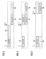
- FIG. 1 shows, in the form of a schematic drawing, an exemplary embodiment of a device for unsorted storage, in particular of medicament packs according to the first basic variant of the invention in the plan view (upper part of FIG. 1) and in a side view (lower part of FIG. 1).
- a shelf 1 has a plurality of storage levels arranged one above the other in the form of continuous shelves 2a - 2f.
- the shelves 2a -2f can by two a common travel 11 having storage and retrieval units 3a, 3b, which are horizontally and vertically movable operated.
- the stacker cranes 3a, 3b on manipulation devices which may be formed, for example, as a jaw gripper or suction gripper and are known in the art on.
- the travel path 11 extends over the entire length of the shelf 1.
- the stacker cranes 3a, 3b can both be moved horizontally practically over the entire length of the shelf, but can not happen to each other. If the latter is desired, separate travel paths 11 can be provided for the two storage and retrieval units 3a, 3b, which run parallel to each other at a sufficient distance.
- two transfer tables 5a, 5b are longitudinally displaceable within the storage lane, in which the two stacker cranes 3a, 3b are movable. As can be seen from the side view, the two transfer tables 5a, 5b are equipped with wheels, so formed as a car.
- a drive is provided, which in the case illustrated schematically in the form of a chain drive 10 is formed.
- a belt conveyor 8 is arranged outside of the shelf 1, ie on the storage and retrieval devices 3a, 3b side facing away from the shelf 1, to which the goods can be placed individually.
- the individual goods can be passed past a scanner at a feeding station 9, for example manually, in order to uniquely identify each product.
- Each individual product is then transported by the conveyor belt 8 in the direction of the arrow shown to the right in the area of a transfer device 4.
- the transfer device As soon as a product enters the workspace of a converter, not shown, the transfer device, which can be detected for example by means not also shown photocells , the translator, preferably designed as a uniaxial robot, which can have a jaw gripper, picks up the goods and transports them horizontally through a corresponding opening in the shelves 2 onto the transfer table 5 in the transfer area 6 and places them on the transfer table 5a in a defined intermediate storage position from. Thereafter, the transfer table 5a moves a small piece to allow the inclusion of another product at the same relative to the converter body, which is retrieved from the belt conveyor 8 after retraction of the converter. In this way, a filling of the transfer table 5a can be carried out successively.
- the control unit receives the information about the individual clipboard positions on the transfer table and stores.
- the Transfer table 5a On the initiative of the control unit in a removal position, which is provided in the present case at the left end of the shelf 1 (shown in phantom) and is denoted by 5a '.
- the controller can position the respective stacker crane 3a, 3b so in that targeted access to each of the new goods to be stored on the transfer table 5a is ensured.
- the second transfer table 5b can be positioned within the transfer area 6 in a corresponding manner so that further goods are temporarily stored on the transfer table 5b via the converter, while the stacker crane 3a feeds the transfer table 5a successively empties.
- the second storage and retrieval unit 3b can pick up individual goods for storage from the transfer table 5a.
- the stacker crane 3b remains idle in the right part of the bearing 1 or, for example, outsources individual stored goods upon request.
- the transfer table 5b is then moved out of the transfer area 6 in the appropriate removal position 7b, which is preferably arranged in mirror image to the removal position 7a of the transfer table 5a, that is in the region of the right end of the shelf 1.
- storage of the goods can now be made via the stacker crane 3b in a corresponding manner. After emptying the transfer table 5a this can in turn be moved into the transfer area 6 for receiving additional goods until all new goods to be stored are processed.
- the shelf 1 could also be provided to divide the shelf 1 in two part racks, which are arranged at a distance from each other in the longitudinal direction one behind the other.
- the transfer device 4 would then be in the area between the arranged two partial shelves. While in FIG. 1 the shelf 1 is arranged in a single line, in the modification according to FIG. 2 it is provided that the shelf 1 is assigned a second shelf 1 'at a parallel distance.
- the two stacker cranes 3a, 3b are within the storage lane formed between the two shelves 1, 1 'over the entire length of the shelves 1, 1' movable. Both stacker cranes 3a, 3b are preferably designed so that they can serve both shelves 1, 1 '. For this purpose, their manipulation means for handling the goods are arranged pivotable about a vertical axis of rotation. Incidentally, the function of this device for storing goods is the same as in FIG. 1.
- FIG. 3 as in FIGS. 1 and 2, two transfer tables 5a, 5b are also provided.
- the two transfer tables 5a, 5b within the covered by the shelves of the shelf 1 floor plan area, which is indicated as a dotted line schematically arranged.
- the transfer device 4 is merely indicated by an arrow which designates the feed direction of the individual goods.
- the transfer device 4 is again arranged approximately in the middle of the shelf 1.
- the width of the two transfer tables 5a, 5b is about half the width of the shelves of the shelf 1.
- the transfer table 5a is in a removal position and the transfer table 5b within the transfer area, so it can be moved with new goods to be stored.
- the position for the takeover of new goods by the transfer table 5a is shown in phantom and denoted by 5a '.
- the transfer tables 5a, 5b are movable past each other and over the full length of the shelf 1 in both directions, as can be seen for example from Figure 5, in which also two transfer tables 5a, 5b are provided movable parallel to each other.
- the transfer device 4 is not arranged in the middle region but in the region of the right-hand end of the shelf 1.
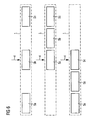
- FIG. 4 shows a modification of FIG. 3 in which two transfer tables 5a, 5b and 5c, 5d are respectively provided on the two lanes. All four transfer tables 5a - 5d each have separately controllable drives, so they can be moved independently of each other.
- this constellation it is possible that two storage and retrieval devices are supplied via the transfer tables located in a removal position 5a, 5d with new goods to be stored, while at the same time from the outside new goods for temporary storage on the two transfer area located in the transfer tables 5b, 5c can be abandoned. With such a constellation, an extremely high throughput rate with regard to the storage processes is made possible.
- the configuration of the transfer tables 5a-5d according to FIG. 4 but also in the configuration according to FIGS.
- Figure 6 shows a further, particularly advantageous embodiment of the invention, in which three transfer tables 5a - 5c are provided, which are movable in a common lane and have a table width which corresponds approximately to the depth of the shelves 2 of the shelf 1, so that the width of Regalgasse does not need to be enlarged.
- This configuration has the advantage that it is always possible for two of the transfer tables 5a-5c to be lockable in a removal position, while at the same time one is available for loading by the converter in the transfer region 6 and can freely carry out the required advancing movements. Therefore, when using two storage and retrieval units, both are each assigned their own transfer table for the storage of goods.
- transfer tables 5a-5c can not pass each other, it may only be necessary to have a brief interruption and a change of the removal position during unloading of a transfer table 5a-5c to bring an empty transfer table 5a-5c into the transfer area 6 to be able to.
- the individual positions during the loading of the individual transfer tables 5a-5c can be seen from the three schematics of FIG.
- the two outer transfer tables 5a and 5c are in a removal position and the middle table 5b in the transfer area (transfer device 4).
- the left transfer table 5a has been moved to the transfer area;
- the removal position for the transfer table 5b is therefore in the right half of the shelf 1 in this situation.
- the transfer table 5c in the transfer area can be loaded by the transfer device 4, while the two other transfer tables 5a and 5b are each in a removal position in the left Half of the shelf 1 are kept.
- FIG. 7 shows in its lower part a view of the longitudinal side of an automatic rack system 1 according to the second basic variant of the invention from the inside.
- the entire system is housed in a housing to protect the stored objects from harmful environmental influences.
- the shelves which are designated by the reference numeral 2, sometimes have different distances from each other to accommodate objects of different heights can.
- the shelves 2 Apart from a central area, in which a loading device 31 and a row of trays 37 are accommodated on the front side to the left and right sides of the loading device 31, the shelves 2 extend practically over the entire length of the rack 1, which in the upper part of FIG 7 is shown in plan view. Overall, it is only a schematic representation in which the enclosure itself is not shown.
- the plant has two stacker cranes 3a, 3b, which are movable in the case shown on a common rail 21.
- New items to be stored are z. B. by an operator by hand on a feed belt 8, whose conveying direction is indicated by an arrow and which runs on the outside of the rack system 1 parallel to the longitudinal extent thereof.
- a breakthrough in the outer wall is arranged in order to be able to lead the objects placed on the outside into the interior of the racking system 1.
- the latter is preferably done in an automated form by a Umsetzbackengreifer, as he is known in particular from the shelves of Apostore GmbH.
- This jaw gripper 14 and the feed belt 8 are shown again in FIG. 10 in an external view of the housing of the rack system 1.
- FIG. 8 shows, similar to FIG. 2, a variant of the rack system according to the invention, which has two partial shelves 1, 1 'lying opposite one another.
- the two part racks 1, 1 ' are spaced apart, so that between them a storage lane 25 is formed, in which a running rail 21 for two storage and retrieval units 3a, 3b is laid.
- a running rail 21 for two storage and retrieval units 3a, 3b is laid.
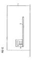
- FIG. 9 is merely a schematic representation of the installation according to the invention, in the center of which is the loading device 31.
- the latter has a frame-like base frame, on whose upper side in the region of the longitudinal sides a sliding track 32 formed from angle profiles is arranged.
- the angle profiles are positioned at a parallel distance from each other, wherein the distance corresponds to the width of trays 37, which are additionally marked to distinguish in Figure 9 with individual letters a to f and the intermediate storage area of the buffer storage of the rack 1 form.
- a linear guide 16 for a sliding carriage 34 which by means of a driven by a drive motor 36 reversibly driven toothed belt 33 which is coupled to the sliding carriage 34, over the entire length the loading device 31 is displaced back and forth.
- a coupling device 35 is attached to the sliding carriage 34 respectively.
- the trays 37 are each designed as substantially flat sheets, on the underside of non-visible skids made of plastic are attached.
- the trays 37 are expediently in immediate connection to the right and left end of the loading device 31 to the two sides in their transfer positions.
- On the trays 37a, 37c, 37e each items 38 are stored and are available for the final storage by a not shown in Figure 9 storage and retrieval system without restriction.
- the shelves 37b, 37d, 37f located in the right-hand part are empty and are available for the buffer storage of objects to be newly placed.
- the trays 37 each have a lock 15a or 15b in the region of their end face facing the loading device 31, which corresponds to the coupling device 5.
- the shelves 37 are arranged in a similar manner as the shelves 2 within the rack system 1 and have a similar width and length as the illustrated sections of the shelf 2. In contrast to the latter, however, the trays 37 are displaceably mounted in the longitudinal direction.
- This shift is carried out in an automated manner by the sliding carriage 34. For example, by moving the sliding carriage 34 to the left, the left part of the coupling device 35 by approaching the lock 15 a to the tray 37 a couple when the contact pressure by the toothed belt driven sliding carriage 34 against that by a Stop held tray 37a exceeds a certain value. This locks the Coupling device 35 in the lock 15 a.
- the drive motor 36 can be reversed in its direction of rotation, so that the tray 37a is pulled onto the sliding track 32 and reaches a takeover position on the loading device 31.
- the tray 37b from its right end position which is also the transfer position for unloading by the storage and retrieval unit, not shown, are moved to the left.
- the loading device 31 In order to be able to pull the other trays 37c, 73e or 37f, 37d in a corresponding manner on the loading device 31, the loading device 31 must be brought with its base frame previously in a corresponding lower position of height corresponding to the respective transfer position.
- the loading device 31 is provided with two vertical guides 40 and a motor-actuated spindle drive 11, which are each coupled to the base frame of the charging device 31.
- the base frame whose length is about twice as large as the length of a tray 37, has reached a level corresponding to the respective tray 37, the coupling can take place in the manner described above.
- the rear wall 12, not shown in detail in FIG. 9, of the enclosure of the racking system 1 would lie in the region of the auxiliary lines shown in phantom, which run through the rear corners of the shelves 2 or the trays 37.
- vertical supports could be arranged, which serve to hold the shelves 2 and the shelves 37.
- by omitting individual shelves 2 arbitrarily many shelves 37 can be accommodated in a suitable transfer position, so that, if necessary, the available area of the buffer memory on each desired value can be increased or reduced. At most, a change in the length of the vertical guides 40 and the spindle drive 11 would be made. Incidentally, no complicated structural adjustments are required.
- a task belt 8 on which the new items to be stored are placed.
- Means for identifying and measuring the objects are not shown in detail in FIG. Suitable devices for this purpose are familiar to the expert.
- transfer point 13 the transfer of the individual newly launched, but not shown in Figure 9 items takes place.
- a Umsetzbackengreifer 14 is provided, the drives are not shown in detail but merely symbolized by corresponding arrows for the movements.
- the Umsetzbackengreifer 14 can take an object and aligns it exactly by its plane-parallel jaws. The gripped object is then pulled over a bridging plate 17 which covers the existing gap between the feed belt 8 and a tray 37 (not shown in FIG.
- this bridging plate 17 from a light-transmitting material such as glass, in particular safety glass, in order to be able to operate, for example, scanners for identifying the objects in the region of the gap.
- FIG. 11 shows an example of the depositing of individual objects 38 on a tray 37 by the transfer jaw gripper 14.
- the device according to the invention can also be used to store rollable objects 38, that is to say in particular lying cylindrical objects such as bottles or tubes.
- rollable objects 38 that is to say in particular lying cylindrical objects such as bottles or tubes.
- precautions must be taken to prevent inadvertent shifting (e.g., caused by advancing motion or jarring) of the articles from their clipboard position on the tray or their final storage position on the shelf 2.
- a task belt 8 to the task of newly stored items 38 may not be able to roll away these.
- the surfaces of the shelves and trays 37 and optionally also the surface of the feed belt 8 at least partially with a rolling-preventing structuring, in particular transversely to the longitudinal direction of the shelves 2 and the trays 37 and transverse to the transport direction of the feed belt To provide 8 extending ribs.
- a device which determines the information required by the control unit to the dimensions of the goods to be stored in an indirect manner, that does not measure itself in the literal sense.
- the dimensions e.g. of drug packages may have previously been determined in the sense of master data and stored in a data store, from which they can be retrieved after determining the identity of a product in each case on the basis of the identification number.
Claims (42)
- Dispositif pour stocker et déstocker par ordinateur, en particulier pour stocker sans les trier des marchandises, en particulier des objets parallélépipédiques comme des emballages de médicaments, comportant- au moins un rayonnage (1, 1') ayant plusieurs sols de rayonnage (2a à 2f) placés les uns au-dessus des autres,- au moins un appareil (3a, 3b) desservant les rayonnages qui peut se déplacer horizontalement et verticalement le long des sols de rayonnage (2a à 2f) pour stocker et pour déstocker les marchandises,- un dispositif de transfert (4) pour fournir, dans la zone de travail de l'au moins un appareil (3a, 3b) de desserte, les marchandises qui sont chargées à l'extérieur du rayonnage à un poste de chargement (9) et qui doivent être déposées sur les sols de rayonnage (2a à 2f),- une installation d'identification pour identifier les marchandises à stocker,- une installation de mesure pour déterminer les dimensions en longueur des marchandises nécessaires pour le stockage et- une unité de commande de l'appareil (3a, 3b) de desserte et munie d'une mémoire de données, en particulier d'une mémoire de données au moins pour des données suivantes :- des positions verticales des sols de rayonnage (2a à 2f),- des données de position, représentatives de la position horizontale d'une marchandise déposée dans le sens de la longueur du sol de rayonnage (2a à 2f) respectif,- des dimensions en longueur détectées des marchandises,caractérisé en ce que- le dispositif de transfert (4) a au moins deux tables de transfert (5a à 5d) sur lesquelles les marchandises à stocker nouvellement peuvent être stockées temporairement dans des positions définies de dépôt intermédiaire, les au moins deux tables de transfert (5a, 5b) étant mobiles entre une zone de prise en charge (6) pour la prise en charge de marchandises à stocker nouvellement et au moins une position de retrait pour le retrait des marchandises temporairement stockées par l'appareil (3) de desserte,- dans la zone de prise en charge (6), au moins l'une des tables de transfert (5a à 5d) peut être respectivement mise ou maintenue successivement dans des positions de prise en charge pour prendre en charge des marchandises à stocker nouvellement et au lieu de cela au moins un autre peut être respectivement mis ou maintenu dans au moins une position de retrait (7a, 7b) et- il est prévu des moyens qui transmettent à l'unité de commande des informations sur les positions de dépôt intermédiaire respectives, d'une façon qui assure que l'au moins un appareil (3a, 3b) ait un accès sélectif à chaque marchandise à stocker nouvellement placée sur la table de transfert (5a à 5d).
- Dispositif selon la revendication 1, caractérisé en ce que les plateaux de transfert (5a, 5b) peuvent se déplacer le long des sols de rayonnage (2a à 2f) entre la zone de prise en charge (6) et la position de retrait.
- Dispositif selon la revendication 2, caractérisé en ce qu'il est prévu trois plateaux de transfert (5a à 5c) mobiles sur une voie de circulation commune, à chaque fois un des plateaux de transfert (5a à 5c) peut être apportée dans la zone de prise en charge (6) pour assurer le chargement et les deux autres dans une position de retrait (7a, 7b) ou ils peuvent être maintenus dans ces positions.
- Dispositif selon la revendication 2, caractérisé en ce qu'il est prévu quatre plateaux de transfert (5a à 5d), dont deux sont respectivement mobiles sur une voie de circulation commune et leurs deux voies de circulation sont parallèles et à distance l'une de l'autre et qu'à chaque fois deux plateaux de transfert (5a à 5d) peuvent être apportées dans la zone de prise en charge (6), alors que les deux autres plateaux de transfert (5) le sont dans l'au moins une position de retrait (7a, 7b) correspondante.
- Dispositif selon la revendication 2, caractérisé en ce qu'on prévoit deux plateaux de transfert (5a à 5d) qui peuvent aller et venir, sur toute la longueur de l'au moins un rayonnage (1), sur des voies de circulation parallèles à distance l'une de l'autre, l'unité de commande pouvant coupler au choix le mouvement des deux plateaux de transfert (5a à 5d) de telle manière que les deux plateaux de transfert (5a à 5d) forment un plateau de transfert mobile commun.
- Dispositif selon l'une des revendications 1 à 5, caractérisé en ce que les plateaux de transfert (5a à 5d) peuvent être bloquées dans leur position de retrait (7a, 7b) pendant la durée de retrait des marchandises temporairement stockées.
- Dispositif selon l'une des revendications 1 à 6, caractérisé en ce que les plateaux de transfert (5a à 5d) se trouvent à l'intérieur de la zone de plan horizontal recouverte par les sols de rayonnage (2a à 2f), en particulier entre deux sols de rayonnage (2a à 2e) qui se trouvent l'un juste sur l'autre.
- Dispositif selon l'une des revendications 1 à 6, caractérisé en ce que les plateaux de transfert (5a, 5b) sont placés en partie ou en totalité à l'extérieur de la zone de plan horizontal recouverte par les sols de rayonnage (2a à 2f).
- Dispositif selon l'une des revendications 1 à 8, caractérisé en ce que, quand on regarde dans le sens longitudinal des sols de rayonnage (2a à 2f), au moins une position de retrait (7a, 7b) des plateaux de transfert (5a, 5b) est placée dans la zone d'une extrémité du rayonnage (1).
- Dispositif selon l'une des revendications 1 à 9, caractérisé en ce que, quand on regarde dans le sens longitudinal du rayonnage (1), l'endroit où les marchandises à stocker nouvellement peuvent être déposées de l'extérieur du rayonnage (1) sur le plateau de transfert (5a à 5d) concerné se trouve dans sa zone centrale.
- Dispositif selon l'une des revendications 1 à 10, caractérisé en ce que les plateaux de transfert (5a à 5d) peuvent aller et venir entre l'au moins une position de retrait (7a, 7b) et la zone de prise en charge (6) à l'aide d'un moyen de traction (10), en particulier à l'aide d'un entraînement à chaîne, à câble ou à courroie.
- Dispositif selon l'une des revendications 1 à 10, caractérisé en ce que les plateaux de transfert (5a à 5d) peuvent être déplacés à l'aide d'un entraînement linéaire.
- Dispositif selon l'une des revendications 1 à 12, caractérisé en ce que l'au moins une position de retrait (7a, 7b) peut être définie par une butée.
- Dispositif selon l'une des revendications 1 à 13, caractérisé en ce que les plateaux de transfert (5a à 5d) consistent chacun en une voiture ou un chariot.
- Dispositif selon l'une des revendications 1 à 14, caractérisé en ce que chaque surface de dépôt sur les plateaux de transfert (5a à 5d) est en un matériau flexible tendu, en particulier en une bande de tissu ou en une bande de matière plastique ou de caoutchouc.
- Dispositif selon la revendication 2, caractérisé en ce qu'il est prévu comme plateaux de transfert (5a à 5d) un grand nombre d'étages, qu'un convoyeur peut successivement transporter par rotation entre une position de chargement dans la zone de prise en charge (6) et une position de retrait dans la zone de travail de l'appareil (3a, 3b)de desserte et les marchandises d'un étage donné, qui peut être maintenu immobile un certain temps, sont stockées par l'appareil (3a, 3b) de desserte pendant qu'on charge d'autres marchandises dans un autre étage.
- Magasin selon la revendication 16, caractérisé en ce que le convoyeur est un convoyeur à bande, à courroie ou à chaîne.
- Magasin selon l'une des revendications 16 ou 17, caractérisé en ce que pour faire tourner successivement les étages on prévoit deux trajets de convoyage, parallèles et en sens contraire, un poussoir qui pousse respectivement un étage depuis un trajet de convoyage sur l'autre se trouvant au début et à la fin des trajets de convoyage.
- Dispositif selon la revendication 1, caractérisé en ce que le dispositif de transfert (4) comporte un dispositif de chargement (31) et un grand nombre d'étages (37) sur lesquels les objets (38) peuvent être stockés temporairement servent de plateaux de transfert, que le dispositif de chargement (31) peut se déplacer verticalement entre une position de chargement et au moins une position de déchargement et que, grâce au dispositif de chargement (31), les étages (37) peuvent se déplacer sur le dispositif de chargement (31) pour procéder respectivement au déchargement dans la position de retrait à l'intérieur de la zone d'accès de l'appareil (3a, 3b) de desserte et au chargement dans une position de prise en charge sur le dispositif (31) de chargement dans la zone de prise en charge (6).
- Dispositif selon la revendication 19, caractérisé en ce que le dispositif de chargement (31) et chaque position de retrait des étages (37) se trouvent dans la zone des sols de rayonnage (2).
- Dispositif selon la revendication 20, caractérisé en ce qu'il est prévu pour les étages (37) un grand nombre de positions de retrait, qui se suivent immédiatement sur un côté frontal du dispositif de chargement (31), en particulier sur ses deux côtés frontaux.
- Dispositif selon la revendication 21, caractérisé en ce qu'il est prévu au moins deux positions de retrait l'une au-dessus de l'autre.
- Dispositif selon l'une des revendications 19 à 22, caractérisé en ce que, pendant le chargement, chaque étage (37) peut être poussé pas à pas en position de prise en charge sur le dispositif de chargement (31).
- Dispositif selon l'une des revendications 19 à 23, caractérisé en ce que le dispositif de chargement (31) comporte un chariot coulissant (34) qui peut se déplacer par moteur sur un guidage linéaire (16) dans le sens longitudinal du dispositif de chargement (31) parallèlement au sens longitudinal des sols de rayonnage (2), en particulier à l'aide d'une courroie dentée (33) réversible et en ce que le chariot coulissant (34) peut être à volonté couplé aux étages (37)ou en être découplé.
- Dispositif selon la revendication 24, caractérisé en ce que le chariot coulissant (34) comporte au moins un embrayage (5), en particulier un embrayage pour chaque sens de déplacement, qui peut être actionné en série par pression mécanique et qui coopère respectivement avec un verrou (15a, 15b) correspondant dans la zone d'un côté frontal des étages (37).
- Dispositif selon l'une des revendications 19 à 25, caractérisé en ce que les étages (37) sont essentiellement des tôles plates et leur côté inférieur est respectivement muni de patins, en particulier de patins en matière plastique.
- Dispositif selon la revendication 26, caractérisé en ce que le dispositif de chargement (31) comporte un bâti de base sur lequel est placée une coulisse (32) comportant un guidage latéral pour les étages (37), en particulier sous forme de profilés en équerre parallèles et à distance l'un de l'autre.
- Dispositif selon l'une des revendications 19 à 27, caractérisé en ce que le dispositif de chargement (31) est guidé par au moins deux guidages verticaux (40).
- Dispositif selon la revendication 8, caractérisé en ce que, pour gagner de la place, les guidages verticaux (40) se trouvent à l'extérieur du plan horizontal des sols de rayonnage (2) dans la zone des supports verticaux du rayonnage (1), les sols de rayonnage (2) étant fixés directement ou indirectement à ces supports verticaux.
- Dispositif selon l'une des revendications 19 à 29, caractérisé en ce qu'un mécanisme motorisé à broche (11) est prévu pour déplacer verticalement le dispositif de chargement (1) .
- Dispositif selon l'une des revendications 19 à 30, caractérisé en ce que, en position de retrait, les étages (37) peuvent être arrêtés l'un au-dessus de l'autre à différentes distances, en particulier à des distances modifiables.
- Dispositif selon l'une des revendications 19 à 31, caractérisé en ce que plusieurs étages (37) chargés peuvent être fournis en même temps pour que l'au moins un appareil (3a, 3b) de desserte ait accès à volonté aux objets (38) stockés temporairement.
- Dispositif selon l'une des revendications 1 à 32, caractérisé en ce que l'au moins un appareil (3a, 3b) de desserte est muni d'un organe préhenseur (26) pour prendre un ou plusieurs objets (38.
- Dispositif selon l'une des revendications 1 à 33, caractérisé en ce que, pour stocker des objets (38) cylindriques horizontaux, les surfaces des sols de rayonnage (2) et des étages (37) ou des plateaux de transfert (5a à 5d), ainsi que, le cas échéant, aussi les surfaces de la bande de remise (8) sont au moins en partie munies d'une structure qui empêche de rouler, en particulier munies de nervures transversales au sens longitudinal des sols de rayonnage (2) ou des étages (37) ou transversales à la direction de transport de la bande de remise (8).
- Dispositif selon l'une des revendications 1 à 34, caractérisé en ce que le dispositif de transfert (4) comporte un convertisseur, relié à l'unité de commande, qui reçoit à l'extérieur de la zone du rayonnage (1) les marchandises à stocker nouvellement et les dépose orientées dans la zone de prise en charge (6) sur l'au moins un plateau de transfert (5a à 5d) ou l'étage (37).
- Dispositif selon la revendication 35, caractérisé en ce que le convertisseur, au sens d'un robot à un axe, comporte un organe préhenseur (14) qui peut se déplacer linéairement à l'horizontale.
- Dispositif selon l'une des revendications 35 ou 36, caractérisé en ce que, à l'extérieur du rayonnage (1), les marchandises (38) à stocker nouvellement peuvent être convoyées depuis le poste de remise (9) jusque dans la zone de travail du convertisseur par un convoyeur (8), en particulier par un convoyeur à bande (bande de remise 8).
- Dispositif selon l'une des revendications 1 à 37, caractérisé en ce que l'au moins un appareil (3a, 3b) de desserte se trouve dans une allée de rayonnage entre deux rayonnages (1, 1') dont les grands côtés se font face, le dispositif de transfert (4) se trouvant dans la zone d'un des deux rayonnages (1, 1').
- Dispositif selon l'une des revendications 35 à 38, caractérisé en ce que, en sens longitudinal, l'au moins un rayonnage (1) consiste en deux sous-rayonnages placés à distance l'un derrière l'autre et le convertisseur du dispositif de transfert (4) est prévu dans la zone entre les sous-rayonnages.
- Dispositif selon l'une des revendications 38 ou 39, caractérisé en ce que deux appareils (3a, 3b) de desserte qui peuvent fonctionner indépendamment l'un de l'autre se trouvent dans chaque allée de rayonnages et leur zone de travail comprend respectivement les deux rayonnages (1, 1') qui se font face.
- Dispositif selon la revendication 40, caractérisé en ce que les appareils (3a, 3b) de desserte ont des trajectoires à distance l'une de l'autre et quand ils se déplacent ils peuvent passer l'un devant l'autre dans le sens longitudinal des rayonnages.
- Dispositif selon la revendication 40, caractérisé en ce que les deux appareils (3a, 3b) de desserte n'ont qu'une trajectoire (21) commune exploitable.
Applications Claiming Priority (6)
| Application Number | Priority Date | Filing Date | Title |
|---|---|---|---|
| DE102004007694 | 2004-02-16 | ||
| DE200410007692 DE102004007692A1 (de) | 2004-02-16 | 2004-02-16 | Verbesserungen an einem automatischen Lager, insbesondere Apothekenlager |
| DE102004007692 | 2004-02-16 | ||
| DE200410007694 DE102004007694B4 (de) | 2004-02-16 | 2004-02-16 | Vorrichtung zum Lagern von Waren |
| DE102004046176A DE102004046176B4 (de) | 2004-09-23 | 2004-09-23 | Verfahren zum rechnergesteuerten Ein- und Auslagern von Gegenständen und Vorrichtung zur Durchführung dieses Verfahrens |
| DE102004046176 | 2004-09-23 |
Publications (2)
| Publication Number | Publication Date |
|---|---|
| EP1564160A1 EP1564160A1 (fr) | 2005-08-17 |
| EP1564160B1 true EP1564160B1 (fr) | 2006-05-03 |
Family
ID=34704642
Family Applications (1)
| Application Number | Title | Priority Date | Filing Date |
|---|---|---|---|
| EP05002954A Active EP1564160B1 (fr) | 2004-02-16 | 2005-02-11 | Dispositif de stockage d'objets |
Country Status (4)
| Country | Link |
|---|---|
| EP (1) | EP1564160B1 (fr) |
| AT (1) | ATE325055T1 (fr) |
| DE (1) | DE502005000006D1 (fr) |
| ES (1) | ES2262124T3 (fr) |
Families Citing this family (6)
| Publication number | Priority date | Publication date | Assignee | Title |
|---|---|---|---|---|
| DE202021106858U1 (de) | 2021-08-10 | 2022-06-28 | Knapp Smart Solutions Gmbh | Kommissioniervorrichtung |
| DE102021004093A1 (de) | 2021-08-10 | 2023-02-16 | Knapp Smart Solutions Gmbh | Verfahren zum Instandsetzen einer Kommissioniervorrichtung |
| DE202021106835U1 (de) | 2021-08-10 | 2022-06-27 | Knapp Smart Solutions Gmbh | Kommissioniervorrichtung |
| DE102022114943B4 (de) | 2022-04-08 | 2024-04-11 | Knapp Ag | Umverpackungsvorrichtung zum Umverpacken von in Tablettenform vorliegenden Medikamenten und Verfahren zum Betreiben einer Umverpackungsvorrichtung |
| WO2023194555A1 (fr) | 2022-04-08 | 2023-10-12 | Knapp Ag | Procédé pour faire fonctionner un dispositif de suremballage destiné à suremballer des médicaments présents sous la forme de comprimés et procédé pour faire fonctionner un dispositif de suremballage |
| EP4273060A1 (fr) | 2022-04-08 | 2023-11-08 | Knapp AG | Procédé de fonctionnement d'un dispositif d'emballage pour re-emballer des médicaments se présentant sous forme de comprimés et procédé de fonctionnement d'un dispositif d'emballage |
Family Cites Families (5)
| Publication number | Priority date | Publication date | Assignee | Title |
|---|---|---|---|---|
| GB1157071A (en) * | 1965-07-12 | 1969-07-02 | P E Consulting Group Ltd | Improvements in and relating to apparatus for the Storage and Handling of Items |
| US5174454A (en) * | 1991-11-15 | 1992-12-29 | Parkander Gothe A K | Method for sorting form stacks in storage systems and a device for carrying out the method |
| DE19509951C2 (de) * | 1995-03-18 | 1997-03-13 | Rudolf M Dipl Ing Wagner | Vorrichtung zum unsortierten Lagern von Waren oder sonstigen Gegenständen |
| DE10102999B4 (de) * | 2001-01-24 | 2008-10-16 | Wagner, Rudolf M., Dipl.-Ing. | Verfahren zur unsortierten Lagerung von Arzneimittelpackungen, die Abholer-Arzneimittelpackungen einschließen |
| US6610954B2 (en) * | 2001-02-26 | 2003-08-26 | At&C Co., Ltd. | System for sorting commercial articles and method therefor |
-
2005
- 2005-02-11 DE DE502005000006T patent/DE502005000006D1/de active Active
- 2005-02-11 ES ES05002954T patent/ES2262124T3/es active Active
- 2005-02-11 AT AT05002954T patent/ATE325055T1/de active
- 2005-02-11 EP EP05002954A patent/EP1564160B1/fr active Active
Also Published As
| Publication number | Publication date |
|---|---|
| EP1564160A1 (fr) | 2005-08-17 |
| ATE325055T1 (de) | 2006-06-15 |
| ES2262124T3 (es) | 2006-11-16 |
| DE502005000006D1 (de) | 2006-06-08 |
Similar Documents
| Publication | Publication Date | Title |
|---|---|---|
| DE102011014394C5 (de) | Zirkulares Roaming für ein Lager- und Kommissioniersystem | |
| EP1598291B1 (fr) | Dispositif et procédé automatique de stockage d'objets | |
| EP2794432B1 (fr) | Système de stockage sur rayonnages et son procédé de fonctionnement | |
| DE4213542C2 (de) | Regalanordnung | |
| EP0407703B1 (fr) | Procédé et dispositif pour stocker et déstocker des caissons contenant des matériaux en forme de bâton ou de plaque dans un magasin à rayonnage | |
| EP0458021B1 (fr) | Entrepôt avec rayonnages pour matériel recueilli dans des cassettes autoporteuses | |
| AT506221B1 (de) | Verfahren und transportvorrichtung zum positionieren von ladehilfsmitteln vor deren übergabe in ein regalfach | |
| AT511140B1 (de) | Regallagersystem und verfahren zum betreiben desselben | |
| EP2287093B1 (fr) | Système de rayonnage et procédé de fonctionnement d'un système de rayonnage | |
| DE2406378C3 (de) | Lagerhauseinrichtung | |
| AT506284A1 (de) | Verfahren zum einlagern von ladehilfsmitteln und transportvorrichtung | |
| WO2013004695A1 (fr) | Système et procédé d'entrée d'un produit à stocker dans un rayon et de sortie hors du rayon | |
| EP1820754A2 (fr) | Système d'étagère et procédé de stockage automatisé de petits objets | |
| EP2753558B1 (fr) | Poste de préparation de commande et méthode de préparation de commande d'articles avec aide au chargement | |
| EP1564160B1 (fr) | Dispositif de stockage d'objets | |
| DE3830373A1 (de) | Automatisch arbeitendes lager- und transportsystem zur ver- und entsorgung von arbeitsplaetzen | |
| DE102004046176B4 (de) | Verfahren zum rechnergesteuerten Ein- und Auslagern von Gegenständen und Vorrichtung zur Durchführung dieses Verfahrens | |
| EP1902976A1 (fr) | Procédé pour le déstockage rapide des articles d'un magasin de stockage et un magasin de stockage correspondant | |
| DE2407756A1 (de) | Vorrichtung zum entspeichern von warenkanaelen | |
| DE102004025070B4 (de) | Verfahren und Vorrichtung zur Einlagerung von Waren in eine automatisierte Lagervorrichtung | |
| DE2711677C2 (de) | Palettenbe- oder Entladevorrichtung | |
| EP0798238B1 (fr) | Système d'entreposage pour palettes pour objets longs | |
| DE102004007694B4 (de) | Vorrichtung zum Lagern von Waren | |
| EP3106412B1 (fr) | Groupement de marchandises | |
| DE3343732A1 (de) | Ausruestung zum palettieren schicht fuer schicht auf entsprechende paletten von verschiedenartigen, aus gesonderten kanaelen zugefuehrten gegenstaenden |
Legal Events
| Date | Code | Title | Description |
|---|---|---|---|
| PUAI | Public reference made under article 153(3) epc to a published international application that has entered the european phase |
Free format text: ORIGINAL CODE: 0009012 |
|
| AK | Designated contracting states |
Kind code of ref document: A1 Designated state(s): AT BE BG CH CY CZ DE DK EE ES FI FR GB GR HU IE IS IT LI LT LU MC NL PL PT RO SE SI SK TR |
|
| AX | Request for extension of the european patent |
Extension state: AL BA HR LV MK YU |
|
| GRAP | Despatch of communication of intention to grant a patent |
Free format text: ORIGINAL CODE: EPIDOSNIGR1 |
|
| 17P | Request for examination filed |
Effective date: 20050922 |
|
| GRAC | Information related to communication of intention to grant a patent modified |
Free format text: ORIGINAL CODE: EPIDOSCIGR1 |
|
| GRAS | Grant fee paid |
Free format text: ORIGINAL CODE: EPIDOSNIGR3 |
|
| GRAA | (expected) grant |
Free format text: ORIGINAL CODE: 0009210 |
|
| AK | Designated contracting states |
Kind code of ref document: B1 Designated state(s): AT DE ES FR GB IT |
|
| PG25 | Lapsed in a contracting state [announced via postgrant information from national office to epo] |
Ref country code: IT Free format text: LAPSE BECAUSE OF FAILURE TO SUBMIT A TRANSLATION OF THE DESCRIPTION OR TO PAY THE FEE WITHIN THE PRESCRIBED TIME-LIMIT;WARNING: LAPSES OF ITALIAN PATENTS WITH EFFECTIVE DATE BEFORE 2007 MAY HAVE OCCURRED AT ANY TIME BEFORE 2007. THE CORRECT EFFECTIVE DATE MAY BE DIFFERENT FROM THE ONE RECORDED. Effective date: 20060503 |
|
| REG | Reference to a national code |
Ref country code: GB Ref legal event code: FG4D Free format text: NOT ENGLISH |
|
| AKX | Designation fees paid |
Designated state(s): AT DE ES FR GB IT |
|
| GBT | Gb: translation of ep patent filed (gb section 77(6)(a)/1977) |
Effective date: 20060504 |
|
| REF | Corresponds to: |
Ref document number: 502005000006 Country of ref document: DE Date of ref document: 20060608 Kind code of ref document: P |
|
| REG | Reference to a national code |
Ref country code: ES Ref legal event code: FG2A Ref document number: 2262124 Country of ref document: ES Kind code of ref document: T3 |
|
| ET | Fr: translation filed | ||
| PLBE | No opposition filed within time limit |
Free format text: ORIGINAL CODE: 0009261 |
|
| STAA | Information on the status of an ep patent application or granted ep patent |
Free format text: STATUS: NO OPPOSITION FILED WITHIN TIME LIMIT |
|
| 26N | No opposition filed |
Effective date: 20070206 |
|
| PGFP | Annual fee paid to national office [announced via postgrant information from national office to epo] |
Ref country code: FR Payment date: 20070222 Year of fee payment: 3 |
|
| REG | Reference to a national code |
Ref country code: FR Ref legal event code: ST Effective date: 20081031 |
|
| PG25 | Lapsed in a contracting state [announced via postgrant information from national office to epo] |
Ref country code: FR Free format text: LAPSE BECAUSE OF NON-PAYMENT OF DUE FEES Effective date: 20080229 |
|
| PGRI | Patent reinstated in contracting state [announced from national office to epo] |
Ref country code: IT Effective date: 20090401 |
|
| PGFP | Annual fee paid to national office [announced via postgrant information from national office to epo] |
Ref country code: GB Payment date: 20100219 Year of fee payment: 6 |
|
| GBPC | Gb: european patent ceased through non-payment of renewal fee |
Effective date: 20110211 |
|
| PG25 | Lapsed in a contracting state [announced via postgrant information from national office to epo] |
Ref country code: GB Free format text: LAPSE BECAUSE OF NON-PAYMENT OF DUE FEES Effective date: 20110211 |
|
| PGFP | Annual fee paid to national office [announced via postgrant information from national office to epo] |
Ref country code: ES Payment date: 20230317 Year of fee payment: 19 Ref country code: AT Payment date: 20230215 Year of fee payment: 19 |
|
| PGFP | Annual fee paid to national office [announced via postgrant information from national office to epo] |
Ref country code: IT Payment date: 20230228 Year of fee payment: 19 Ref country code: DE Payment date: 20230320 Year of fee payment: 19 |
|
| P01 | Opt-out of the competence of the unified patent court (upc) registered |
Effective date: 20230506 |
|
| PGFP | Annual fee paid to national office [announced via postgrant information from national office to epo] |
Ref country code: ES Payment date: 20240319 Year of fee payment: 20 |
|
| PGFP | Annual fee paid to national office [announced via postgrant information from national office to epo] |
Ref country code: AT Payment date: 20240216 Year of fee payment: 20 |