EP1564063A1 - Kontinuierliche Herstellung von Schleifleisten aus Kohlenstoff mit einem geringen Anteil an dünnen metallischen Leitern - Google Patents
Kontinuierliche Herstellung von Schleifleisten aus Kohlenstoff mit einem geringen Anteil an dünnen metallischen Leitern Download PDFInfo
- Publication number
- EP1564063A1 EP1564063A1 EP05002761A EP05002761A EP1564063A1 EP 1564063 A1 EP1564063 A1 EP 1564063A1 EP 05002761 A EP05002761 A EP 05002761A EP 05002761 A EP05002761 A EP 05002761A EP 1564063 A1 EP1564063 A1 EP 1564063A1
- Authority
- EP
- European Patent Office
- Prior art keywords
- thin metallic
- compacting
- composite material
- green
- metallic conductor
- Prior art date
- Legal status (The legal status is an assumption and is not a legal conclusion. Google has not performed a legal analysis and makes no representation as to the accuracy of the status listed.)
- Withdrawn
Links
Images
Classifications
-
- C—CHEMISTRY; METALLURGY
- C04—CEMENTS; CONCRETE; ARTIFICIAL STONE; CERAMICS; REFRACTORIES
- C04B—LIME, MAGNESIA; SLAG; CEMENTS; COMPOSITIONS THEREOF, e.g. MORTARS, CONCRETE OR LIKE BUILDING MATERIALS; ARTIFICIAL STONE; CERAMICS; REFRACTORIES; TREATMENT OF NATURAL STONE
- C04B35/00—Shaped ceramic products characterised by their composition; Ceramics compositions; Processing powders of inorganic compounds preparatory to the manufacturing of ceramic products
- C04B35/515—Shaped ceramic products characterised by their composition; Ceramics compositions; Processing powders of inorganic compounds preparatory to the manufacturing of ceramic products based on non-oxide ceramics
- C04B35/52—Shaped ceramic products characterised by their composition; Ceramics compositions; Processing powders of inorganic compounds preparatory to the manufacturing of ceramic products based on non-oxide ceramics based on carbon, e.g. graphite
- C04B35/528—Shaped ceramic products characterised by their composition; Ceramics compositions; Processing powders of inorganic compounds preparatory to the manufacturing of ceramic products based on non-oxide ceramics based on carbon, e.g. graphite obtained from carbonaceous particles with or without other non-organic components
- C04B35/532—Shaped ceramic products characterised by their composition; Ceramics compositions; Processing powders of inorganic compounds preparatory to the manufacturing of ceramic products based on non-oxide ceramics based on carbon, e.g. graphite obtained from carbonaceous particles with or without other non-organic components containing a carbonisable binder
-
- B—PERFORMING OPERATIONS; TRANSPORTING
- B60—VEHICLES IN GENERAL
- B60L—PROPULSION OF ELECTRICALLY-PROPELLED VEHICLES; SUPPLYING ELECTRIC POWER FOR AUXILIARY EQUIPMENT OF ELECTRICALLY-PROPELLED VEHICLES; ELECTRODYNAMIC BRAKE SYSTEMS FOR VEHICLES IN GENERAL; MAGNETIC SUSPENSION OR LEVITATION FOR VEHICLES; MONITORING OPERATING VARIABLES OF ELECTRICALLY-PROPELLED VEHICLES; ELECTRIC SAFETY DEVICES FOR ELECTRICALLY-PROPELLED VEHICLES
- B60L5/00—Current collectors for power supply lines of electrically-propelled vehicles
- B60L5/18—Current collectors for power supply lines of electrically-propelled vehicles using bow-type collectors in contact with trolley wire
- B60L5/20—Details of contact bow
- B60L5/205—Details of contact bow with carbon contact members
-
- H—ELECTRICITY
- H01—ELECTRIC ELEMENTS
- H01B—CABLES; CONDUCTORS; INSULATORS; SELECTION OF MATERIALS FOR THEIR CONDUCTIVE, INSULATING OR DIELECTRIC PROPERTIES
- H01B1/00—Conductors or conductive bodies characterised by the conductive materials; Selection of materials as conductors
- H01B1/14—Conductive material dispersed in non-conductive inorganic material
- H01B1/18—Conductive material dispersed in non-conductive inorganic material the conductive material comprising carbon-silicon compounds, carbon or silicon
-
- B—PERFORMING OPERATIONS; TRANSPORTING
- B32—LAYERED PRODUCTS
- B32B—LAYERED PRODUCTS, i.e. PRODUCTS BUILT-UP OF STRATA OF FLAT OR NON-FLAT, e.g. CELLULAR OR HONEYCOMB, FORM
- B32B2315/00—Other materials containing non-metallic inorganic compounds not provided for in groups B32B2311/00 - B32B2313/04
- B32B2315/02—Ceramics
-
- B—PERFORMING OPERATIONS; TRANSPORTING
- B60—VEHICLES IN GENERAL
- B60L—PROPULSION OF ELECTRICALLY-PROPELLED VEHICLES; SUPPLYING ELECTRIC POWER FOR AUXILIARY EQUIPMENT OF ELECTRICALLY-PROPELLED VEHICLES; ELECTRODYNAMIC BRAKE SYSTEMS FOR VEHICLES IN GENERAL; MAGNETIC SUSPENSION OR LEVITATION FOR VEHICLES; MONITORING OPERATING VARIABLES OF ELECTRICALLY-PROPELLED VEHICLES; ELECTRIC SAFETY DEVICES FOR ELECTRICALLY-PROPELLED VEHICLES
- B60L2200/00—Type of vehicles
- B60L2200/26—Rail vehicles
-
- C—CHEMISTRY; METALLURGY
- C04—CEMENTS; CONCRETE; ARTIFICIAL STONE; CERAMICS; REFRACTORIES
- C04B—LIME, MAGNESIA; SLAG; CEMENTS; COMPOSITIONS THEREOF, e.g. MORTARS, CONCRETE OR LIKE BUILDING MATERIALS; ARTIFICIAL STONE; CERAMICS; REFRACTORIES; TREATMENT OF NATURAL STONE
- C04B2235/00—Aspects relating to ceramic starting mixtures or sintered ceramic products
- C04B2235/02—Composition of constituents of the starting material or of secondary phases of the final product
- C04B2235/30—Constituents and secondary phases not being of a fibrous nature
- C04B2235/42—Non metallic elements added as constituents or additives, e.g. sulfur, phosphor, selenium or tellurium
- C04B2235/422—Carbon
-
- C—CHEMISTRY; METALLURGY
- C04—CEMENTS; CONCRETE; ARTIFICIAL STONE; CERAMICS; REFRACTORIES
- C04B—LIME, MAGNESIA; SLAG; CEMENTS; COMPOSITIONS THEREOF, e.g. MORTARS, CONCRETE OR LIKE BUILDING MATERIALS; ARTIFICIAL STONE; CERAMICS; REFRACTORIES; TREATMENT OF NATURAL STONE
- C04B2235/00—Aspects relating to ceramic starting mixtures or sintered ceramic products
- C04B2235/02—Composition of constituents of the starting material or of secondary phases of the final product
- C04B2235/30—Constituents and secondary phases not being of a fibrous nature
- C04B2235/42—Non metallic elements added as constituents or additives, e.g. sulfur, phosphor, selenium or tellurium
- C04B2235/422—Carbon
- C04B2235/424—Carbon black
-
- C—CHEMISTRY; METALLURGY
- C04—CEMENTS; CONCRETE; ARTIFICIAL STONE; CERAMICS; REFRACTORIES
- C04B—LIME, MAGNESIA; SLAG; CEMENTS; COMPOSITIONS THEREOF, e.g. MORTARS, CONCRETE OR LIKE BUILDING MATERIALS; ARTIFICIAL STONE; CERAMICS; REFRACTORIES; TREATMENT OF NATURAL STONE
- C04B2235/00—Aspects relating to ceramic starting mixtures or sintered ceramic products
- C04B2235/02—Composition of constituents of the starting material or of secondary phases of the final product
- C04B2235/30—Constituents and secondary phases not being of a fibrous nature
- C04B2235/42—Non metallic elements added as constituents or additives, e.g. sulfur, phosphor, selenium or tellurium
- C04B2235/422—Carbon
- C04B2235/425—Graphite
-
- C—CHEMISTRY; METALLURGY
- C04—CEMENTS; CONCRETE; ARTIFICIAL STONE; CERAMICS; REFRACTORIES
- C04B—LIME, MAGNESIA; SLAG; CEMENTS; COMPOSITIONS THEREOF, e.g. MORTARS, CONCRETE OR LIKE BUILDING MATERIALS; ARTIFICIAL STONE; CERAMICS; REFRACTORIES; TREATMENT OF NATURAL STONE
- C04B2235/00—Aspects relating to ceramic starting mixtures or sintered ceramic products
- C04B2235/02—Composition of constituents of the starting material or of secondary phases of the final product
- C04B2235/30—Constituents and secondary phases not being of a fibrous nature
- C04B2235/48—Organic compounds becoming part of a ceramic after heat treatment, e.g. carbonising phenol resins
-
- C—CHEMISTRY; METALLURGY
- C04—CEMENTS; CONCRETE; ARTIFICIAL STONE; CERAMICS; REFRACTORIES
- C04B—LIME, MAGNESIA; SLAG; CEMENTS; COMPOSITIONS THEREOF, e.g. MORTARS, CONCRETE OR LIKE BUILDING MATERIALS; ARTIFICIAL STONE; CERAMICS; REFRACTORIES; TREATMENT OF NATURAL STONE
- C04B2235/00—Aspects relating to ceramic starting mixtures or sintered ceramic products
- C04B2235/60—Aspects relating to the preparation, properties or mechanical treatment of green bodies or pre-forms
- C04B2235/602—Making the green bodies or pre-forms by moulding
-
- C—CHEMISTRY; METALLURGY
- C04—CEMENTS; CONCRETE; ARTIFICIAL STONE; CERAMICS; REFRACTORIES
- C04B—LIME, MAGNESIA; SLAG; CEMENTS; COMPOSITIONS THEREOF, e.g. MORTARS, CONCRETE OR LIKE BUILDING MATERIALS; ARTIFICIAL STONE; CERAMICS; REFRACTORIES; TREATMENT OF NATURAL STONE
- C04B2235/00—Aspects relating to ceramic starting mixtures or sintered ceramic products
- C04B2235/65—Aspects relating to heat treatments of ceramic bodies such as green ceramics or pre-sintered ceramics, e.g. burning, sintering or melting processes
- C04B2235/658—Atmosphere during thermal treatment
- C04B2235/6582—Hydrogen containing atmosphere
-
- C—CHEMISTRY; METALLURGY
- C04—CEMENTS; CONCRETE; ARTIFICIAL STONE; CERAMICS; REFRACTORIES
- C04B—LIME, MAGNESIA; SLAG; CEMENTS; COMPOSITIONS THEREOF, e.g. MORTARS, CONCRETE OR LIKE BUILDING MATERIALS; ARTIFICIAL STONE; CERAMICS; REFRACTORIES; TREATMENT OF NATURAL STONE
- C04B2235/00—Aspects relating to ceramic starting mixtures or sintered ceramic products
- C04B2235/70—Aspects relating to sintered or melt-casted ceramic products
- C04B2235/74—Physical characteristics
- C04B2235/77—Density
-
- C—CHEMISTRY; METALLURGY
- C04—CEMENTS; CONCRETE; ARTIFICIAL STONE; CERAMICS; REFRACTORIES
- C04B—LIME, MAGNESIA; SLAG; CEMENTS; COMPOSITIONS THEREOF, e.g. MORTARS, CONCRETE OR LIKE BUILDING MATERIALS; ARTIFICIAL STONE; CERAMICS; REFRACTORIES; TREATMENT OF NATURAL STONE
- C04B2235/00—Aspects relating to ceramic starting mixtures or sintered ceramic products
- C04B2235/70—Aspects relating to sintered or melt-casted ceramic products
- C04B2235/96—Properties of ceramic products, e.g. mechanical properties such as strength, toughness, wear resistance
-
- C—CHEMISTRY; METALLURGY
- C04—CEMENTS; CONCRETE; ARTIFICIAL STONE; CERAMICS; REFRACTORIES
- C04B—LIME, MAGNESIA; SLAG; CEMENTS; COMPOSITIONS THEREOF, e.g. MORTARS, CONCRETE OR LIKE BUILDING MATERIALS; ARTIFICIAL STONE; CERAMICS; REFRACTORIES; TREATMENT OF NATURAL STONE
- C04B2237/00—Aspects relating to ceramic laminates or to joining of ceramic articles with other articles by heating
- C04B2237/30—Composition of layers of ceramic laminates or of ceramic or metallic articles to be joined by heating, e.g. Si substrates
- C04B2237/32—Ceramic
- C04B2237/36—Non-oxidic
- C04B2237/363—Carbon
-
- C—CHEMISTRY; METALLURGY
- C04—CEMENTS; CONCRETE; ARTIFICIAL STONE; CERAMICS; REFRACTORIES
- C04B—LIME, MAGNESIA; SLAG; CEMENTS; COMPOSITIONS THEREOF, e.g. MORTARS, CONCRETE OR LIKE BUILDING MATERIALS; ARTIFICIAL STONE; CERAMICS; REFRACTORIES; TREATMENT OF NATURAL STONE
- C04B2237/00—Aspects relating to ceramic laminates or to joining of ceramic articles with other articles by heating
- C04B2237/30—Composition of layers of ceramic laminates or of ceramic or metallic articles to be joined by heating, e.g. Si substrates
- C04B2237/40—Metallic
- C04B2237/407—Copper
Definitions
- Rail-bound vehicles powered by electric motors receive the necessary Electricity mostly via an abrasive strip, which is on a support element of a pantograph on the Vehicle is mounted.
- the sanding strip touches the stationary, arranged in the direction of travel Power supply - usually a contact wire -, and slides when driving the vehicle to the Power supply or along the contact wire.
- the distance between rail and contact wire is on the entire driving distance is constant. Small changes in the distance between the rail and contact wire are during compensated for the drive through the pantograph.
- the contact strip in the case of a distance change receives a sudden load and in the case of an increase in distance even the contact between contact wire and contact strip can be lost in the short term because the compensating movement of the pantograph with support and contact strip is not fast enough. Both effects are weaker when the inertia of the carrier and contact strip is small. Therefore, small masses of carrier and grinding bar are desired. Measured by the density of common, highly electrically conductive metals, the density of carbons of abrasive strips is low. However, to obtain sufficient electrical conductivity or low electrical resistance of these carbons, these carbons require metals as an additive.
- the inertia of such abrasive bars is higher than the inertia of carbon strips only.
- the heating of the grinding bar in operation is a noteworthy size.
- the sanding strip must not overheat at high currents. Otherwise, the sanding strip itself, the contact wire or the gluing, with which the sanding strip is in many cases attached to the support, are damaged.
- Japanese Patent JP 1270571 (1989) discloses a low resistivity strip material.
- Low resistivity is manifested by the incorporation of copper wire mesh into the carbon matrix and by impregnation of a low melting alloy pore system present in the carbon matrix , B. copper-tin reached.
- the objective formulated in this document is achieved of obtaining a grinding bar material with good self-lubricating properties.
- the impregnation with copper-tin gives this material a relatively high metal content and the density of this abrasive strip material is at least 3.2 g / cm 3 . It is therefore not the goal of the Japanese inventors to achieve a material with low density and thus a grinding bar with low inertia.
- Japanese Patent Publication JP 4207903 and JP 4207904 disclose abrasive strip materials having low resistivities and high fracture toughness.
- the high fracture toughnesses are achieved by the addition of metallic fibers in a proportion of 5 to 60% by volume of the mixture of carbon and fibers. Preferably, the fiber volume fraction is 10 to 45 vol .-%.
- the metallic fibers are quenched in an additional heat treatment process.
- both writings are metallic short fibers, not endless fibers. This has the consequence that a relatively high fiber component is needed to ensure the contacts of the fibers with each other and in this way to achieve current paths with low electrical resistance. This means a high metal content and thus at the same time a relatively high density, which precludes carbon materials with the density of the invention.
- Japanese Patent JP 4280865 describes a wiper strip material with very good impact resistance and sliding properties.
- the abrasive strip material consists of carbon material and metal fibers and / or metal powder.
- the metal fibers - are arranged asymmetrically in the sanding strip - even in various textile presentation.
- the metal fibers are oriented to the side facing away from the contact wire or oriented to the carrier-facing side.
- the content of metal fibers is high. At one point of the font, it is given as 30 vol.%.
- the density of these material composites is correspondingly high.
- a carbon-rich material for the Sliding current collection contains layered metallic conductors.
- the metallic ladder are z. B. fiber bundles by textile processes - such. B. weaving - in flat structures be implemented.
- the electric current flows virtually unhindered.
- the carbon-rich material contains metallic pens that the Passing through levels of metallic conductors substantially vertically and electrically connect.
- the continuous production of a compacted, endless profile of a material composite of green carbon material and a thin metallic conductor has the advantage that one is not limited as in the die pressing in the component length or as in extruding a homogeneous material structure.
- the production of abrasive rails in the length used on the locomotives required unusually heavy and expensive die presses with long dies to press the associated green bodies of the abrasive rails. Extrusion of green bodies for abrasive rails of the type referred to in the preamble of claim 1 is not possible. In the extruded profile, the thin metallic conductors would not be obtainable in the desired orderly manner.
- Roll compacting is suitable for various work steps: on the one hand, the free-flowing green mixture can be continuously compressed into strips, on the other hand, two or more such strips can be pressed together to form a uniform shaped body.
- An essential prerequisite for the first compression to a belt is that the green mixture is in free-flowing form.
- the content of the hydrocarbon-containing binder of the green mixture is 10 to 50% by weight.
- the hydrocarbon-containing binders are the pitches or synthetic resins commonly used in carbon technology.
- For the rolling Compalctieren a free-flowing green mixture is used with a Komverotti of 10 microns to 500 microns.
- the layer of thin metallic conductor is used in rolling compacting, either on both sides approximately in the same thickness of the initially free-flowing, then compacted green mixture covered or the situation is so used that they only one-sided from the first trickle, then compacted green mixture is covered.
- metallic conductors for roll compacting, comparatively thin and flexible metallic conductors in the form of layers of wires, strands or tapes with thicknesses of individual filaments of less than 0.4 mm are used.
- Metallic conductors are copper or copper alloys.
- the wires, strands or bands are either substantially unidirectionally single or serrated, each spaced apart from one another, or arranged substantially multidirectionally. The latter corresponds in terms of Leiterorientie- tion a two- or multi-axis tissue.
- Such multiaxial fabrics are also suitable as layers of thin metallic conductors in the carbon bands according to the invention. However, these tissues must not form a closed layer. Instead, perforated mesh fabrics are to be used. If no mesh fabric but closed fabric used, the latter provide the cohesion of the carbon profile or This is usually the cause of delaminations caused by mechanical shock or by significant differences in the thermal expansion coefficients - effective z. B. when burning - be triggered.
- the aforementioned textile forms of the thin metallic conductor are in one layer so used that at least 40% of the area of this layer of compacted green Mixture exist.
- At least one pair of rolls is used, which has a defined set nip and two with the same but opposing mantle speed of running rolls.
- the axes of such Roller pair are arranged in a horizontal plane. That's convenient because on in this way, pour the free-flowing green mixture into the nip of the roller pair can.
- the free-flowing green mixture and the thin metallic conductors - the total Precursors - and the resulting densified profile of the green carbon material or the Material composite are continuously substantially vertically from top to bottom promoted.
- the compacted, endless profile of a green carbon material or a composite material with thin metallic conductors has such a cohesion that it without More to handle. Therefore, two or more such compressed profiles become further treatment by pairs of rollers, their axes in a vertical plane are arranged.
- the compacted, endless profiles themselves are superimposed at Temperatures of 20 to 120 ° C substantially horizontally in the roll compacting verwalzt.
- Roll compacting is a continuous process with the compacted body from a composite of green carbon and thin metallic conductors getting produced.
- a composite material according to the invention contains less than 5% by volume of metals.
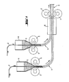
- the diagram of an overall plant for the continuous production of a shaped body (8) gives an overview of how the shaped bodies (8) of green carbon and thin metallic conductor are formed from different precursors (2), (3).
- the continuous production of two - instead of several - similar compressed profiles (1) of a composite material is shown.
- For each profile (1) of a composite material applies: In a hopper (4) is given the free-flowing green mixture (3).
- the amount of the green mixture flowing out of the filling funnel (4) and entering the nip of the roller pair (5) is regulated.
- a layer of a thin metallic conductor (2) is drawn into the nip.
- This layer (2) enters from above into the filling funnel (4) filled with the free-flowing green mixture (3). It is guided so that it is either covered on both sides in about the same thickness of the first free-flowing, then compressed in the nip green mixture or the situation (2) is guided so that they only one side of the first free-flowing, then in the Nip compressed green mixture is covered. From the pair of rollers (5) occurs continuously the compressed profile (1) of a composite material - consisting of the precursors (2), (3) - out. Thanks to their good cohesion, the at least two profiles (1) of the material composite, which arise at the same time in a vertical direction from top to bottom, can be easily handled and can therefore be deflected by 90 °.
- the at least two profiles (1) are then conveyed substantially horizontally and combined to a temperature control chamber for preheating (6). At temperatures of at least 20 ° C and at most 120 ° C they are rolled with another pair of rollers (7) to a shaped body (8).
Landscapes
- Engineering & Computer Science (AREA)
- Chemical & Material Sciences (AREA)
- Ceramic Engineering (AREA)
- Mechanical Engineering (AREA)
- Power Engineering (AREA)
- Transportation (AREA)
- Inorganic Chemistry (AREA)
- Manufacturing & Machinery (AREA)
- Dispersion Chemistry (AREA)
- Materials Engineering (AREA)
- Structural Engineering (AREA)
- Organic Chemistry (AREA)
- Current-Collector Devices For Electrically Propelled Vehicles (AREA)
Abstract
- Mischen der trockenen Kohlenstoffkomponenten und der Additive mit kohlenwasserstoffhaltigem Bindemittel,
- kontinuierliches Walz-Kompaktieren des Materialverbundes aus grünem Kohlenstoffmaterial und dünnem metallischen Leiter
- Brennen des zunächst grünen Formkörpers unter dem Schutzgas Wasserstoff und
- Bearbeiten des so erhaltenen Materialverbundes zu Schleifleisten, die die dünnen metallischen Leiter in der gewünschten Orientierung enthalten.
Description
- Mischen der trockenen Kohlenstoffkomponenten und der Additive mit kohlenwasserstoffhaltigem Bindemittel,
- Brennen des zunächst grünen Formkörpers unter dem Schutzgas Wasserstoff und
- Bearbeiten des so erhaltenen Materialverbundes zu Schleifleisten, die die dünnen metallischen Leiter in der gewünschten Orientierung enthalten.
Bei geringen Fahrzeuggeschwindigkeiten ist die Geschwindigkeit der Ausgleichsbewegung des Pantographen schnell genug, um die Schleifleiste stets an den Fahrdraht anzudrücken und so den Stromübergang zu ermöglichen. Dabei werden die senkrecht zur Längsachse des Fahrdrahtes auf diesen ausgeübten Kräfte im Wesentlichen durch die im Pantographen eingestellten Spannkräfte bestimmt.
Bei hohen Fahrzeuggeschwindigkeiten treten zu den aus den Spannkräften des Pantographen resultierenden Kräften weitere hinzu. Diese resultieren zu einem erheblichen Anteil aus der Massenträgheit der Bauteile des Pantographen. Tragelement - häufig auch als "Träger" oder "Schleifleistenträger" bezeichnet - und Schleifleiste tendieren wegen ihrer Trägheit, in konstantem Abstand zur Schiene zu verharren.
Gemessen an der Dichte gängiger, elektrisch gut leitfähiger Metalle ist die Dichte der Kohlenstoffe von Schleifleisten gering. Um jedoch eine ausreichende elektrische Leitfähigkeit beziehungsweise einen niedrigen elektrischen Widerstand dieser Kohlenstoffe zu erhalten, benötigen diese Kohlenstoffe Metalle als Additiv. Meist werden die Metalle in Form einer Metallimprägnierung des porösen Kohlenstoffes zugegeben, womit diese Werkstoffverbunde eine Dichte aufweisen, die über der von nicht mit Metall imprägnierten Kohlenstoffen liegt. Damit ist die Trägheit solcher Schleifleisten höher als die Trägheit von nur aus Kohlenstoff bestehenden Schleifleisten.
Neben der Massenträgheit und neben dem niedrigen elektrischen Widerstand ist die Erwärmung der Schleifleiste im Betrieb eine zu beachtende Größe. Die Schleifleiste darf sich bei hohen Strömen nicht übermäßig erwärmen. Andernfalls werden die Schleifleiste selber, der Fahrdraht oder die Klebung, mit der die Schleifleiste in vielen Fällen am Träger befestigt ist, geschädigt.
- Unter einer grünen Mischung versteht man in der Kohlenstofftechnik ein Gemisch aus Trockenstoffen aus der Gruppe der Kokse, des Elektrographits, des Naturgraphits, der Ruße u. a. mit den gewünschten Kornbändern, der kohlenwasserstoffhaltigen Bindemittel und der Additive, Wenn Peche als Bindemittel eingesetzt werden, findet das Mischen bei Temperaturen oberhalb des Erweichungspunktes der Peche statt. Nach dem Mischen und Abkühlen auf Raumtemperatur liegt die grüne Mischung zunächst in nicht verarbeitbaren Schollen vor. Um diese in eine verarbeitungs- und dosierfähige Form zu bringen, werden die Schollen in einer Sekundärmahlung zu einer rieselfähigen Körnung mit geeigneten Korngrößen zerkleinert.
- Die rieselfähige grüne Mischung wird zusammen mit lagenweise eingeführten dünnen metallischen Leitern als Vorprodukt für das Walz-Kompaktieren eingesetzt.
- Beim Walz-Kompaktieren wird die grüne Mischung zusammen mit dünnen metallischen Leitern zwischen den Walzen eines Walzenpaares verdichtet. Werden die Vorprodukte dem Walzenpaar in geeigneter Weise zugeführt, so entsteht kontinuierlich ein Band, dessen Profil von den Abmessungen des Walzenstuhls bestimmt wird.
- Der Widerstand des Materialverbundes wird in Anlehnung an DIN IEC 413, Abschnitt 402
aus den folgenden Angaben errechnet. An den carbonisierten Proben werden die durchfließende
Stromstärke, der Spannungsabfall, die Messlänge und der Querschnitt gemessen.
Bei der Ermittlung dieser Daten wird darauf geachtet, dass Stromstärke und Spannungsabfall nicht nur durch eine Komponente des Materialverbundes - wie etwa die dünnen metallischen Leiter - bestimmt werden. - Bei korrekter Ausführung der Messungen und richtiger Ermittlung des Widerstandes wird ein zutreffender Widerstand für den Materialverbund aus Kohlenstoffmatrix und darin enthaltenen dünnen elektrischen Leitern bestimmt. Dieser Wert wird als "mittlerer spezifischer elektrischer Widerstand" bezeichnet.
- Da in Richtung senkrecht zu den Lagen der dünnen elektrischen Leiter durch diese kaum ein erhöhter Strom fließt, kann an dem Materialverbund in dieser Richtung nur der spezifische elektrische Widerstand der Matrix des gebrannten Kohlenstoffes mit wärmebehandeltem Binder festgestellt werden. Der gewünschte niedrige "mittlere spezifische elektrische Widerstand" wird nur parallel zu den Lagen der dünnen elektrischen Leiter festgestellt. Damit ist auch eine Anisotropie des Werkstoffverbundes festgestellt.
Im Gegensatz zur vorliegenden Erfindung handelt es sich bei beiden Schriften um metallische Kurzfasern, nicht um Endlos-Fasern. Dies hat zur Folge, dass ein relativ hoher Faserauteil benötigt wird, um die Kontakte der Fasern untereinander sicher zu stellen und auf diese Weise Strompfade mit niedrigem elektrischem Widerstand zu erreichen. Dies bedeutet einen hohen Metallanteil und damit zugleich eine relativ hohe Dichte, die Kohlenstoff-Werkstoffen mit der erfindungsgemäßen Dichte entgegensteht.
Die Randbedingungen zu dieser Aufgabe sind, dass die gleitende Stromabnahme zum Betrieb von Fahrzeugen mit Elektromotoren mit Hilfe von Schleifleisten erfolgt und dass die Schleifleisten mittels der bekannten Verfahrensschritte
- Mischen der trockenen Kohlenstoffkomponenten und der Additive mit kohlenwasserstoffhaltigem Bindemittel,
- Brennen des zunächst grünen Formkörpers unter dem Schutzgas Wasserstoff und
- Bearbeiten des so erhaltenen Materialverbundes zu Schleifleisten, die die dünnen metallischen Leiter in der gewünschten Orientierung enthalten, hergestellt werden.
Die Fertigung von Schleifleisten in der auf den Lokomotiven eingesetzten Länge erforderte ungewöhnlich starke und teure Gesenkpressen mit langen Gesenken, um die zugehörigen grünen Körper der Schleifleisten zu pressen, Das Extrudieren von grünen Körpern für Schleifleisten der im Oberbegriff des Anspruchs 1 genannten Art ist nicht möglich. Im extrudierten Profil wären die dünnen metallischen Leiter nicht in der gewünschten geordneten Weise zu erhalten.
Eine wesentliche Voraussetzung für das erste Verdichten zu einem Band ist, dass die grüne Mischung in rieselfähiger Form vorliegt. Der Gehalt an kohlenwasserstoffhaltigem Bindemittel der grünen Mischung beträgt 10 bis 50Gew.-%. Die kohlenwasserstoffhaltigen Bindemittel sind die in der Kohlenstofftechnik gängigen Peche oder Kunstharze.
Für das Walz-Kompalctieren wird eine rieselfähige grüne Mischung mit einer Komverteilung von 10 µm bis 500 µm eingesetzt.
Bandes stark störende Inhomogenität dar. Diese ist meist Ursache für Delaminationen, die durch mechanischen Schock oder durch deutliche Differenzen in den thermischen Ausdehnungskoeffizienten - wirksam z. B. beim Brennen - ausgelöst werden.
- Fig. 1
- Schema einer Gesamtanlage zur kontinuierlichen Herstellung eines Formkörpers (8)
Die mindestens zwei gleichzeitig im Wesentlichen in vertikaler Richtung von oben nach unten entstehenden Profile (1) des Materialverbundes sind Dank ihres guten Zusammenhaltes ohne Weiteres zu handhaben und lassen sich deshalb um 90° umlenken. Die mindestens zwei Profile (1) werden dann im Wesentlichen horizontal gefördert und zusammengefasst einer Temperierkammer zur Vorwärmung (6) zugeführt. Bei Temperaturen von mindestens 20°C und höchstens 120°C werden sie mit einem weiteren Walzenpaar (7) zu einem Formkörper (8) verwalzt.
- 1
- Verdichtetes, endloses Profil eines Materialverbundes aus den Vorprodukten (2), (3)
- 2
- Dünner metallischer Leiter
- 3
- Rieselfähige grüne Mischung
- 4
- Fülltrichter mit Verstelleinrichtung für grüne Mischung
- 5
- Walzenpaar zum Walz-Kompaktieren der Vorprodukte
- 6
- Temperierkammer
- 7
- Walzenpaar zum gemeinsamen Verdichten von mindestens zwei Profilen
- 8
- Formkörper
Claims (18)
- Verfahren zur kontinuierlichen Herstellung eines Materialverbundes und einer daraus herzustellenden Schleifleistedadurch gekennzeichnet, dassbestehend aus einer Matrix von gebranntem Kohlenstoff mit wärmebehandeltem Binder und aus lagenweise darin enthaltenen dünnen metallischen Leitern (2)mit einer Dichte von kleiner oder gleich 2,3g/cm3 undmit einem parallel zu den Lagen der dünnen metallischen Leiter gemessenen mittleren spezifischen elektrischen Widerstand von kleiner oder gleich 3µΩmfür Schleifleisten zur gleitenden Stromabnahme zwecks Betrieb von Fahrzeugen mit Elektromotorenmittels der bekannten VerfahrensschritteMischen der trockenen Kohlenstoffkomponenten und der Additive mit kohlenwasserstoffhaltigem BindemittelBrennen des zunächst grünen Formkörpers unter dem Schutzgas Wasserstoff undBearbeiten des so erhaltenen Materialverbundes zu Schleifleisten, die die dünnen metallischen Leiter in der gewünschten Orientierung enthalten,
nach dem Verfahrensschritt Mischen und vor dem Verfahrensschritt Brennen
mit einem Verfahrensschritt Walz-Kompaktieren ein verdichtetes Profil (1) eines Materialverbundes aus grünem Kohlenstoffmatezial und dünnem metallischen Leiter (2) kontinuierlich erzeugt wird. - Verfahren nach Anspruch 1 dadurch gekennzeichnet, dass
für das Walz-Kompaktieren eine rieselfähige grüne Mischung (3), bevorzugt als Körnung aus einer Sekundannahlung, eingesetzt wird. - Verfahren nach Anspruch 2 dadurch gekennzeichnet, dass
für das Walz-Kompaktieren eine rieselfähige grüne Mischung (3) mit 10 bis 50Gew.-% Bindemittel eingesetzt wird. - Verfahren nach den Ansprüchen 2 und 3 dadurch gekennzeichnet, dass
für das Walz-Kompaktieren aus der Gruppe der kohlenwasserstoffhaltigen Bindemittel Peche oder Kunstharze eingesetzt werden. - Verfahren nach den Ansprüchen 2 bis 4 dadurch gekennzeichnet, dass
für das Walz-Kompaktieren eine rieselfähige grüne Mischung (3) mit einer Kornverteilung von 10 µm bis 500 µm eingesetzt wird. - Verfahren nach Anspruch 1 dadurch gekennzeichnet, dass
für das Walz-Kompaktieren eine rieselfähige grüne Mischung (3) und darin eingebettet eine Lage aus dünnem metallischen Leiter (2) eingesetzt wird. - Verfahren nach Anspruch 6 dadurch gekennzeichnet, dass
die Lage aus dünnem metallischen Leiter (2) so beim Walz-Kompaktieren eingesetzt wird, dass sie auf beiden Seiten etwa in gleicher Stärke von der zunächst rieselfähigen, dann verdichteten grünen Mischung bedeckt ist. - Verfahren nach Anspruch 6 dadurch gekennzeichnet, dass
die Lage aus dünnem metallischen Leiter (2) so beim Walz-Kompaktieren eingesetzt wird, dass sie nur einseitig von der zunächst rieselfähigen, dann verdichteten grünen Mischung bedeckt ist. - Verfahren nach den Ansprüchen 6 bis 8 dadurch gekennzeichnet, dass
für das Walz-Kompaktieren als Lage aus dünnem metallischen Leiter (2) Drähte, Litzen oder Bänder mit Dicken der einzelnen Filamente von weniger als 0,4 mm eingesetzt werden. - Verfahren nach den Ansprüchen 6 bis 9 dadurch gekennzeichnet, dass
in der Lage des dünnen metallischen Leiters (2) Kupferlegierungen oder Kupfer für das Walz-Kompaktieren eingesetzt wird. - Verfahren nach den Ansprüchen 6 bis 10 dadurch gekennzeichnet, dass
in der Lage des dünnen metallischen Leiters (2) die Drähte, Litzen oder Bänder im Wesentlichen unidirektional einzeln oder scharweise, jeweils mit Abständen zueinander für das Walz-Kompaktieren eingesetzt werden. - Verfahren nach den Ansprüchen 6 bis 11 dadurch gekennzeichnet, dass
in der Lage des dünnen metallischen Leiters (2) die Drähte, Litzen oder Bänder im Wesentlichen multidirektional für das Walz-Kompaktieren eingesetzt werden. - Verfahren nach den Ansprüchen 6 bis 12 dadurch gekennzeichnet, dass
in der Lage des dünnen metallischen Leiters (2) solche textilen Formen des Leiters eingesetzt werden, dass mindestens 40% der Fläche dieser Lage aus der verdichteten grünen Mischung bestehen. - Verfahren nach einem oder mehreren der Ansprüche 1 bis 13 dadurch gekennzeichnet, dass
das Walz-Kompaktieren der Vorprodukte zwischen den Walzen von mindestens einem Walzenpaar (5) erfolgt, welches einen definiert eingestellten Walzenspalt aufweist und aus zwei mit gleicher aber gegenläufiger Mantelgeschwindigkeit laufenden Walzen besteht. - Verfahren nach Anspruch 14 dadurch gekennzeichnet, dass
die Vorprodukte und das daraus verdichtete Profil (1) des grünen Kohlenstoffmaterials oder des Materialverbundes kontinuierlich im Wesentlichen vertikal von oben nach unten gefördert werden. - Verfahren nach Anspruch 14 dadurch gekennzeichnet, dass
zwei oder mehrere verdichtete, endlose Profile (1) mit oder ohne Lagen dünner metallischer Leiter (2) übereinander gelegt bei Temperaturen von 20 bis 120°C im Wesentlichen horizontal im Walz-Kompaktieren verwalzt werden. - Verfahren nach einem oder mehreren der Ansprüche 14 bis 16 dadurch gekennzeichnet, dass
in einer Gesamtanlage kontinuierlich mindestens zwei verdichtete Profile (1) zunächst im Wesentlichen in vertikaler Richtung von oben nach unten erzeugt und gefördert werden und nach Umlenken um 90° sowie nach einer Vorwärmung in einer Temperierkammer (6) zusammengefasst und im Wesentlichen horizontal mit Hilfe eines Walzenpaares (7) zu einem Formkörper verwalzt werden. - Materialverbund nach einem oder mehreren der Ansprüche 1 bis 17 dadurch gekennzeichnet, dass
der Materialverbund weniger als 5Vol.-% Metalle enthält.
Applications Claiming Priority (2)
| Application Number | Priority Date | Filing Date | Title |
|---|---|---|---|
| DE200410006589 DE102004006589B4 (de) | 2004-02-10 | 2004-02-10 | Kontinuierliche Herstellung von Schleifleisten aus Kohlenstoff mit einem geringen Anteil an dünnen metallischen Leitern |
| DE102004006589 | 2004-02-10 |
Publications (1)
| Publication Number | Publication Date |
|---|---|
| EP1564063A1 true EP1564063A1 (de) | 2005-08-17 |
Family
ID=34683988
Family Applications (1)
| Application Number | Title | Priority Date | Filing Date |
|---|---|---|---|
| EP05002761A Withdrawn EP1564063A1 (de) | 2004-02-10 | 2005-02-10 | Kontinuierliche Herstellung von Schleifleisten aus Kohlenstoff mit einem geringen Anteil an dünnen metallischen Leitern |
Country Status (2)
| Country | Link |
|---|---|
| EP (1) | EP1564063A1 (de) |
| DE (1) | DE102004006589B4 (de) |
Citations (3)
| Publication number | Priority date | Publication date | Assignee | Title |
|---|---|---|---|---|
| EP0212666A2 (de) * | 1985-08-27 | 1987-03-04 | Intercal Company | Elektrischer Kontakt mit Einlagerungen enthaltendem Graphit |
| US5657842A (en) * | 1995-07-10 | 1997-08-19 | Deutsche Forschungsanstalt Fur Luft Und Raumfahrt B.V. | Brush contact for a vehicle |
| EP1491385A1 (de) * | 2003-06-24 | 2004-12-29 | Sgl Carbon Ag | Schleifleiste aus Kohlenstoff mit einem geringen Anteil an dünnen metallischen Leitern |
Family Cites Families (5)
| Publication number | Priority date | Publication date | Assignee | Title |
|---|---|---|---|---|
| JPH01270571A (ja) * | 1988-04-19 | 1989-10-27 | Nippon Steel Corp | 摺動集電用炭素材料の製造方法 |
| JPH04207904A (ja) * | 1990-11-30 | 1992-07-29 | Nippon Steel Chem Co Ltd | 摺動集電用炭素材料の製造方法 |
| JPH04207903A (ja) * | 1990-11-30 | 1992-07-29 | Nippon Steel Chem Co Ltd | 摺動集電用炭素材料の製造方法 |
| JPH04280865A (ja) * | 1991-03-08 | 1992-10-06 | Sumitomo Metal Ind Ltd | 炭素・金属複合材 |
| JP2000037001A (ja) * | 1998-07-15 | 2000-02-02 | Railway Technical Res Inst | 摺動集電用炭素系材料、及び摺動集電用炭素系材料の製造方法 |
-
2004
- 2004-02-10 DE DE200410006589 patent/DE102004006589B4/de not_active Expired - Fee Related
-
2005
- 2005-02-10 EP EP05002761A patent/EP1564063A1/de not_active Withdrawn
Patent Citations (3)
| Publication number | Priority date | Publication date | Assignee | Title |
|---|---|---|---|---|
| EP0212666A2 (de) * | 1985-08-27 | 1987-03-04 | Intercal Company | Elektrischer Kontakt mit Einlagerungen enthaltendem Graphit |
| US5657842A (en) * | 1995-07-10 | 1997-08-19 | Deutsche Forschungsanstalt Fur Luft Und Raumfahrt B.V. | Brush contact for a vehicle |
| EP1491385A1 (de) * | 2003-06-24 | 2004-12-29 | Sgl Carbon Ag | Schleifleiste aus Kohlenstoff mit einem geringen Anteil an dünnen metallischen Leitern |
Also Published As
| Publication number | Publication date |
|---|---|
| DE102004006589B4 (de) | 2006-09-07 |
| DE102004006589A1 (de) | 2005-09-01 |
Similar Documents
| Publication | Publication Date | Title |
|---|---|---|
| DE69009450T2 (de) | Poröser kohlenstoffkörper mit flachen blattförmigen rippen und herstellungsverfahren. | |
| DE3878719T2 (de) | Vliese aus geschnittenen, orientierten fasern und verfahren und vorrichtung zur herstellung derselben. | |
| DE3221785C2 (de) | Schichtverbundwerkstoff mit metallischer Trägerschicht und Gleit- bzw. Reibschicht, sowie Verfahren zu seiner Herstellung | |
| DE102008015789B4 (de) | Thermisches Sprühpulver, thermische Sprühbeschichtung und Ofenrolle | |
| DE3650282T2 (de) | Elektrischer Kontakt mit Einlagerungen enthaltendem Graphit. | |
| DE212011100077U1 (de) | Graphitelektrode | |
| DE112015001736T5 (de) | Kohlenstoffnanoröhren-Verbundmaterial und Verfahren zu dessen Erzeugung | |
| EP0175877B1 (de) | Polygranularer Kohlenstoffkörper und Verfahren zu seiner Herstellung | |
| DE1240361B (de) | Bimetallstreifen fuer Lager, bestehend aus einem Stahlstuetzteil und einer Metallpulverschicht, und Verfahren zu seiner Herstellung | |
| DE60128133T2 (de) | Herstellungsverfahren für dünne bänder aus metall/keramik-kompositmaterial | |
| DE2350158B2 (de) | Verfahren *ur Herstellung von elektrisch leitfä.higen Bahnen oder Folien f Pll | |
| DE3129946A1 (de) | Werkzeugelektrode, herstellungsverfahren und verwendung derselben | |
| DE112019006226T5 (de) | Thermoelektrisches material und verfahren zu seiner herstellung | |
| DE3621599A1 (de) | Verfahren und vorrichtung zum kontinuierlichen verteilen von fasermaterial | |
| DE69508336T2 (de) | Verfahren zur Herstellung von gemahlenen Graphitfasern | |
| DE2824776C3 (de) | Verfahren zum SRANGGIE;EN VON DRAHTFÖRMIGEN Verstärkungselementen | |
| DE102004006589B4 (de) | Kontinuierliche Herstellung von Schleifleisten aus Kohlenstoff mit einem geringen Anteil an dünnen metallischen Leitern | |
| DE68925936T2 (de) | Kohlenstoff/Metall-Verbundwerkstoff | |
| EP4140609A1 (de) | Strangpressverfahren, rotationsstrangpressmaschine und flachleiter | |
| DE3406418A1 (de) | Verfahren zum aufbringen eines abriebbestaendigen und/oder korrosionsbestaendigen ueberzuges auf einem gegenstand mit unregelmaessiger oberflaeche | |
| EP1491385A1 (de) | Schleifleiste aus Kohlenstoff mit einem geringen Anteil an dünnen metallischen Leitern | |
| DD144151A5 (de) | Verfahren zum verpressen von salzen auf walzenpressen | |
| DE2834943C2 (de) | Verfahren und Vorrichtung zum Herstellen einer fortlaufenden, aus mehreren Lagen zusammengesetzten Matte | |
| DE112021004165T5 (de) | Verbundmaterial und verfahren zur herstellung von formteilen | |
| DE2733063C3 (de) | Tonerde-Agglomerate |
Legal Events
| Date | Code | Title | Description |
|---|---|---|---|
| PUAI | Public reference made under article 153(3) epc to a published international application that has entered the european phase |
Free format text: ORIGINAL CODE: 0009012 |
|
| AK | Designated contracting states |
Kind code of ref document: A1 Designated state(s): AT BE BG CH CY CZ DE DK EE ES FI FR GB GR HU IE IS IT LI LT LU MC NL PL PT RO SE SI SK TR |
|
| AX | Request for extension of the european patent |
Extension state: AL BA HR LV MK YU |
|
| 17P | Request for examination filed |
Effective date: 20060217 |
|
| AKX | Designation fees paid |
Designated state(s): AT BE BG CH CY CZ DE DK EE ES FI FR GB GR HU IE IS IT LI LT LU MC NL PL PT RO SE SI SK TR |
|
| RAP1 | Party data changed (applicant data changed or rights of an application transferred) |
Owner name: FRAUNHOFER-GESELLSCHAFT ZUR FOERDERUNG DER ANGEWAN |
|
| STAA | Information on the status of an ep patent application or granted ep patent |
Free format text: STATUS: THE APPLICATION IS DEEMED TO BE WITHDRAWN |
|
| 18D | Application deemed to be withdrawn |
Effective date: 20090901 |