EP1563587B1 - Dispositif d'entrainement pour dispositifs de reglage de vehicules automobiles - Google Patents
Dispositif d'entrainement pour dispositifs de reglage de vehicules automobiles Download PDFInfo
- Publication number
- EP1563587B1 EP1563587B1 EP03778259A EP03778259A EP1563587B1 EP 1563587 B1 EP1563587 B1 EP 1563587B1 EP 03778259 A EP03778259 A EP 03778259A EP 03778259 A EP03778259 A EP 03778259A EP 1563587 B1 EP1563587 B1 EP 1563587B1
- Authority
- EP
- European Patent Office
- Prior art keywords
- drive device
- housing
- carrier element
- motor
- webs
- Prior art date
- Legal status (The legal status is an assumption and is not a legal conclusion. Google has not performed a legal analysis and makes no representation as to the accuracy of the status listed.)
- Expired - Lifetime
Links
- 230000005540 biological transmission Effects 0.000 claims description 5
- 238000004804 winding Methods 0.000 description 7
- 239000000969 carrier Substances 0.000 description 6
- 210000000078 claw Anatomy 0.000 description 2
- 238000010276 construction Methods 0.000 description 2
- 230000010354 integration Effects 0.000 description 2
- 230000015572 biosynthetic process Effects 0.000 description 1
- 238000006243 chemical reaction Methods 0.000 description 1
- 239000004020 conductor Substances 0.000 description 1
- 230000008030 elimination Effects 0.000 description 1
- 238000003379 elimination reaction Methods 0.000 description 1
- 230000005415 magnetization Effects 0.000 description 1
- 238000012423 maintenance Methods 0.000 description 1
- 238000005259 measurement Methods 0.000 description 1
- 230000001105 regulatory effect Effects 0.000 description 1
- 230000003068 static effect Effects 0.000 description 1
Images


Classifications
-
- H—ELECTRICITY
- H02—GENERATION; CONVERSION OR DISTRIBUTION OF ELECTRIC POWER
- H02K—DYNAMO-ELECTRIC MACHINES
- H02K21/00—Synchronous motors having permanent magnets; Synchronous generators having permanent magnets
- H02K21/12—Synchronous motors having permanent magnets; Synchronous generators having permanent magnets with stationary armatures and rotating magnets
- H02K21/24—Synchronous motors having permanent magnets; Synchronous generators having permanent magnets with stationary armatures and rotating magnets with magnets axially facing the armatures, e.g. hub-type cycle dynamos
-
- H—ELECTRICITY
- H02—GENERATION; CONVERSION OR DISTRIBUTION OF ELECTRIC POWER
- H02K—DYNAMO-ELECTRIC MACHINES
- H02K1/00—Details of the magnetic circuit
- H02K1/06—Details of the magnetic circuit characterised by the shape, form or construction
- H02K1/12—Stationary parts of the magnetic circuit
- H02K1/14—Stator cores with salient poles
-
- H—ELECTRICITY
- H02—GENERATION; CONVERSION OR DISTRIBUTION OF ELECTRIC POWER
- H02K—DYNAMO-ELECTRIC MACHINES
- H02K1/00—Details of the magnetic circuit
- H02K1/06—Details of the magnetic circuit characterised by the shape, form or construction
- H02K1/12—Stationary parts of the magnetic circuit
- H02K1/18—Means for mounting or fastening magnetic stationary parts on to, or to, the stator structures
- H02K1/182—Means for mounting or fastening magnetic stationary parts on to, or to, the stator structures to stators axially facing the rotor, i.e. with axial or conical air gap
-
- H—ELECTRICITY
- H02—GENERATION; CONVERSION OR DISTRIBUTION OF ELECTRIC POWER
- H02K—DYNAMO-ELECTRIC MACHINES
- H02K5/00—Casings; Enclosures; Supports
- H02K5/04—Casings or enclosures characterised by the shape, form or construction thereof
- H02K5/15—Mounting arrangements for bearing-shields or end plates
-
- H—ELECTRICITY
- H02—GENERATION; CONVERSION OR DISTRIBUTION OF ELECTRIC POWER
- H02K—DYNAMO-ELECTRIC MACHINES
- H02K5/00—Casings; Enclosures; Supports
- H02K5/04—Casings or enclosures characterised by the shape, form or construction thereof
- H02K5/16—Means for supporting bearings, e.g. insulating supports or means for fitting bearings in the bearing-shields
- H02K5/167—Means for supporting bearings, e.g. insulating supports or means for fitting bearings in the bearing-shields using sliding-contact or spherical cap bearings
- H02K5/1675—Means for supporting bearings, e.g. insulating supports or means for fitting bearings in the bearing-shields using sliding-contact or spherical cap bearings radially supporting the rotary shaft at only one end of the rotor
-
- H—ELECTRICITY
- H02—GENERATION; CONVERSION OR DISTRIBUTION OF ELECTRIC POWER
- H02K—DYNAMO-ELECTRIC MACHINES
- H02K7/00—Arrangements for handling mechanical energy structurally associated with dynamo-electric machines, e.g. structural association with mechanical driving motors or auxiliary dynamo-electric machines
- H02K7/10—Structural association with clutches, brakes, gears, pulleys or mechanical starters
- H02K7/116—Structural association with clutches, brakes, gears, pulleys or mechanical starters with gears
Definitions
- the invention relates to a drive device for adjusting devices in motor vehicles according to the preamble of claim 1.
- the invention relates to a drive device for adjusting devices in motor vehicles according to the preamble of claim 1.
- WO 00/31859 is a small, flat, portable generator with a plurality of circular magnetic plates with north and south poles with alternating magnetization direction, which are inserted through spaced-apart openings in a circular plastic plate and result in a circular magnetic disk array.
- the two sides of the circular magnetic plate assembly are at a suitable distance opposite magnetic coil plates, glued to the interconnected magnetic coils and which are connected to the output terminals of a rectifier.
- the magnetic coil plates are mounted on a mounting plate and have a central bore through which a shaft connected to the circular magnetic plate assembly is inserted, at the end of a pinion is arranged, which meshes with arranged on the mounting plate gears, with a spring-winding mechanism for driving the Generators are connected.
- WO 00/48 294 is known as an axial field motor or generator electrical machine with a rotatably mounted in a housing rotor and with guided out of the housing rotor shaft known.
- Stationary in the housing are arranged a plurality of electromagnet components at a distance from the rotor shaft axis of rotation at equal angular intervals, each having a coil winding of one or more conductors supporting coil core.
- the pole faces of the end faces of the coil cores are aligned to the pole faces of non-rotatably mounted in or on the rotor permanent magnets, which in the circumferential direction successively each have an opposite polarity.
- the coil cores of the electromagnet components are arranged parallel to the axis of rotation of the rotor shaft in the housing interior, so that their opposite end faces each lie in two mutually spaced, at right angles to the rotor shaft axis of rotation extending planes.
- connection of the disk-shaped rotors with the rotor shaft and their mounting in the housing of the electric machine requires that the rotors and the stator must be completely arranged or mounted in the housing for testing and actuation.
- the support and bearing of the rotor shaft on two sides of the housing requires an exact match between the distance between the supporting points on the housing and the height structure of the stator and the disc-shaped rotors, as a result of axia-len Support the rotor shaft, the risk of over-determination of storage and as a result of high friction losses.
- the invention has for its object to provide a drive device of a Axialfeldmotor and a transmission in which the Axialfeldmotor even without motor housing is functional and can be pretested in its essential properties whose structure excludes over-determinations and thus high friction losses or costly dimensioning, no exact calibration to comply with the air gaps required to the carriers and allows a connection with a self-locking or non-self-locking gear, and allows a flat, space-saving design.
- the solution according to the invention provides an axial field motor which is capable of running even without a motor housing and thus can be pretested in its essential properties and whose structural design excludes over-determinations and thus high friction losses or costly over-dimensioning. Since the radial forces emanating from the motor shaft are introduced into the housing of the drive device or the axial field motor via axially extending positive engagement regions of radial webs, no parts with their tolerances for supporting the motor shaft are required in the axial direction, so that no measurement with thin fitting disks or the like is required necessary is. Compliance with the air gaps, for example, depends only on a vote of the motor shaft and supported on the circumference of the Axialfeldmotors bearing bush for receiving the motor shaft. The design of the Axialfeldmotors allows the connection with different types of gears and the integration of self-locking properties in the Axialfeldmotor a connection with self-locking or non-self-locking gearboxes.
- the integration of the motor shaft in the axial field motor also allows an extremely flat design and by the connection of the gearbox to the axial field motor a very compact design of the drive device.
- the inventive concept for supporting the motor shaft creates with the circumferential support with radially pointing to the center of the Axialfeldmotors webs a virtual motor axis, so that no axial support of the motor shaft is required and thus the height structure of the functional parts of the Axialfeldmotors does not matter.
- the axial field motor is fully functional even without housing and can therefore be pretested and adjusted already in this state.
- the radial webs are supported on the circumference of the Axialfeldmotors and have radially directed end ribs which are connectable in the axial direction with the housing of the Axialfeldmotors or the drive device by preferably engage in form-fitting elements of the housing.
- axially extending form-fitting regions of the radial webs can engage in recesses of the housing.
- the radial webs are formed as part of a support member and are supported by a motor shaft receiving the main body.
- the carrier body can be inserted into a drive housing via the radially directed end ribs which are distributed on the circumference and protrude from the main body of the carrier element, but the functionality of the axial field motor does not depend on the connection to a drive housing.
- An integrated into the main body of the support member bearing bush for receiving the motor shaft may be formed either as part of the main body of the support member or inserted into a corresponding receptacle of the main body of the support member.
- a freestanding, abutting on an end face of the support member outer collar of the bearing bush for fixing the position of the bearing bush within the support member is used.
- the support member is part of the stator of the axial field motor, d. H.
- the function of the carrier element is extended beyond a static function, so that both the number of parts and the production costs are reduced.
- connection of the carrier element and thus of the stator with a housing of the Axialfeldmotors or both the axial field motor and a transmission of the drive device receiving housing serve the radially directed end ribs of the radial webs, which are preferably elastically supported on the housing of the axial field motor or the drive device.
- an at least in the axial direction elastic ring can be arranged, which accommodates tolerances of the two housing halves of a two-part housing and allows axially backlash-free assembly.
- the motor shaft is connected to at least one arranged on one end face of the stator rotor, while the other end face of the stator forms a magnetic yoke.
- the motor shaft is connected to arranged on both faces of the stator runners on which the stator facing permanent magnets are arranged with circumferentially alternating polarity.
- the motor shaft is connected to a pinion of the transmission designed as a spur gear of the drive device.
- the spur gear has a meshing with the pinion gear of a first gear stage, which is coaxially connected to a second pinion of a second gear stage, which meshes with a second gear connected to the drive element of the adjusting device.
- the drive device is preferably arranged in a two-shell housing, whose one housing shell is connected via the elastic ring with the radially directed end ribs of the support element. Furthermore, the elastic ring receiving housing shell fasteners, with which the drive device is connectable to a receiving device.
- the drive device according to the invention is characterized in consequence of the structural features of the Axialfeldmotors by a simple, large tolerances of the individual components permitting assembly in which no consideration for a possible Strain of the axial field motor must be taken.
- the drive device is characterized by the elimination of disturbing noises.
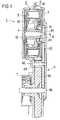
- Fig. 1 shows a longitudinal section through a drive device for an adjusting device in a motor vehicle, for example for a cable window lifter for lifting and lowering a window in a motor vehicle door.
- the drive device includes in an assembled from two housing shells 91, 92 housing 9 an axial field motor 1 with a stator 2 and arranged on both faces of the stator 2 runners 3, 3 ', designed as a spur gear 6 and a drive element of the adjusting device in the form of a rope winding roller 7.
- Fig. 1 shows a longitudinal section through a drive device for an adjusting device in a motor vehicle, for example for a cable window lifter for lifting and lowering a window in a motor vehicle door.
- the drive device includes in an assembled from two housing shells 91, 92 housing 9 an axial field motor 1 with a stator 2 and arranged on both faces of the stator 2 runners 3, 3 ', designed as a spur gear 6 and a drive element of the adjusting device in the form of a rope winding
- the drive device is characterized in particular by a flat design, which is due to the design of the Axialfeldmotors 1 and by using a spur gear 6 and the nested structure in the axial direction of the functional elements of the drive device.
- a tension-free construction without over-determinations is ensured, the essential features of which are to be clarified below.
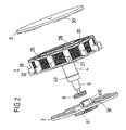
- the axial field motor 1 is in accordance with the Fig. 1 and 2 from a stator 2 and two on both sides of the end faces 27, 28 of the stator 2 arranged carriers 3, 3 'together.
- the one rotor disc 3 is connected to a pinion 61, which forms the output of the Axialfeldmotors 1 and the input of the spur gear 6.
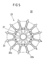
- the carriers 3, 3 ' are connected to a motor shaft 5, which is mounted in a bearing bush 4, which is not supported axially, but via a star-shaped support member 20 which simultaneously forms the mechanical base of the stator 2 of the axial field motor 1.
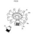
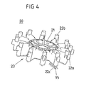
- the support member 20 consists of a base body 21, from which a plurality of webs 22 projects radially, between which slots 23 are formed for receiving bobbins 25, which form by two alternating winding connections each two north and two south poles, so that two north poles each follow two south poles.
- the base body 21 has a cylindrical opening or bore which is designed either as a bearing bush for receiving the motor shaft 5 or into which a bearing bush 4 according to FIGS Fig. 1 and 2 can be used, in which the motor shaft 5 is mounted.
- the bearing bush 4 has a freestanding outer collar 40, which rests against the one end face 26 of the carrier element 20 and thus fixes the position of the bearing bush 4.
- the radial webs 22 have at their outer ends radially directed positive locking elements in the form of radially directed end ribs 22 a, preferably via an elastic ring 10 - as described below with reference to FIG FIGS. 6 and 7 is explained - in positive locking areas of the housing 9 of the Axialfeldmotors or the drive device intervention. Furthermore, axially directed positive locking elements in the form of projections 22b and over the length of the radial webs 22 extending webs 22c are provided, which initiate together with the radially directed end ribs 22a, the radial forces emanating from the motor shaft 5 in the housing 9.
- the counter-form-locking elements of the housing 9 are correspondingly formed as recesses and take with their stop surfaces on the engine forces.
- the webs 22c corresponding recesses 95 of the bottom contour of the housing 9 are assigned, the ends of which are preferably closed for radial guidance of the support member 20.
- the carriers 3, 3 ' are opposite the end faces 26, 27 of the carrier element 20 with the formation of small air gaps and have permanent magnets 30, 30' with circumferentially changing polarity, which form the magnetic inference for the magnetic field of the coils of the stator 2.
- the motor shaft 5 is supported exclusively on the bearing bush 4 and the support member 20 on the circumference of the drive device, ie there is no axial support of the motor shaft 5 with respect to the housing 9, but only a support over the circumference of the housing.
- the axial field motor 1 is independent of the housing 9 of the drive device functional part whose functions can be tested without the housing 9 and without the gear 6 in its function and whose functional parts can be optionally corrected or replaced.
- the connection of the Axialfeldmotors 1 with the housing 9 of the drive device via an elastic ring 10, according to Fig. 6 is placed on the radially directed end ribs 22 a of the radial webs 22 of the support member 20 and according to Fig. 1 on the one housing shell 91 of the clam shell 9 is supported.
- a braking device is provided which ensures a self-locking of the drive device with a torque of the adjusting device, which exceeds the drive torque of the drive device.
- a braking device in the form of a wrap spring brake with a wrap spring 8, which is arranged between the rotor 3 and a connected to the rotor 3 pinion gear 61 of a driven side provided gear and which bears against the outer wall of the stationary bearing bush 4 under bias, in the motor shaft 5 is rotatably mounted.
- the wrap spring 8 via its radially outwardly projecting spring ends which are radially opposite each other.
- the wrap spring 8 is applied when applying a torque introduced from the driven side by means of the pinion 61 in both directions of rotation via one of its spring ends, that it is clamped on the outer edge of the bearing bush 4.
- a torque introduced from the driven side by means of the pinion 61 in both directions of rotation via one of its spring ends, that it is clamped on the outer edge of the bearing bush 4.
- a torque introduced from the driven side by means of the pinion 61 in both directions of rotation via one of its spring ends, that it is clamped on the outer edge of the bearing bush 4.
- a torque introduced from the driven side by means of the pinion 61 in both directions of rotation via one of its spring ends, that it is clamped on the outer edge of the bearing bush 4.
- corresponding extensions or switching claws 610 down from, which cooperate with one of the spring ends of the wrap spring 8.
- the wrap spring brake is locked in the presence of a
- the shift claws 610 of the pinion 61 act on a driven-side torque for locking the wrap spring brake on the ends of the wrap spring 12 in order to contract this, so clamped to the outer wall of the bearing bush 10 to create.
- Each of the two spring ends of the wrap spring 8 is also associated with a switching range of the rotor 3, which solves the wrap spring, ie the wrap spring 8 unlocks when the Axialfeldmotor 2 is energized.
- one or the other switching range acts on the associated spring end of the wrap spring 8 to lift them far from the outer wall of the bearing bush 4, that they no longer counteract a rotational movement and only the lowest possible efficiency losses during operation of the Axialfeldmotors 2 occur ,
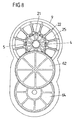
- the transmission of the drive device is according to the Fig. 1 and 6 to 8 from a spur gear 6, whose first gear stage includes the pinion 61 connected to the motor shaft 5, which meshes with a toothed wheel 62 mounted on an axle 65.
- the coaxial with the gear 62 arranged pinion 63 of a second gear stage of the spur gear 6 meshes with a about an axis 66 of the second gear stage rotating gear 64, which in turn is coupled to the drive member 7 of the drive device driven adjusting device, in the embodiment shown here a rope winding roller 7 for a cable window lifter.
- the 6 and 7 show the various perspective views of the Axialfeldmotors and the spur gear and Fig. 8 a plan view of the arranged in the housing 9 functional parts of the drive device, said plan view illustrates the circumferential support of the motor shaft 5.
- Fig. 9 shows in a perspective view of the drive device enclosing housing 9, which is composed of two housing shells 91, 92 as described above. Via a plug connection 93, the drive device with a power supply and / or a control or regulating device is electrically connected, while the mechanical connection of the drive device with a receiving device via fastening elements 94, which are arranged on the one housing shell 91.
Landscapes
- Engineering & Computer Science (AREA)
- Power Engineering (AREA)
- Connection Of Motors, Electrical Generators, Mechanical Devices, And The Like (AREA)
Claims (15)
- Dispositif d'entraînement destiné aux dispositifs de réglage de véhicules automobiles, comprenant un moteur à champ axial et un engrenage qui est relié à l'arbre de moteur et à un élément d'entraînement du dispositif de réglage,
caractérisé en ce que
les forces radiales provenant de l'arbre de moteur (5) sont introduites par le biais de zones de liaison de forme (22a à 22c), s'étendant axialement, de tiges radiales (22) dans le logement (9) du dispositif d'entraînement ou du moteur à champ axial (1), les tiges radiales (22) constituant une partie d'un élément porteur (20) et faisant saillie radialement depuis un corps de base (21) de l'élément porteur (20), dans lequel un coussinet (4) est intégré aux fins de la réception de l'arbre de moteur (5). - Dispositif d'entraînement selon la revendication 1, caractérisé en ce que les tiges radiales (22) sont étayées au niveau de la circonférence du moteur à champ axial (1).
- Dispositif d'entraînement selon la revendication 1 ou 2, caractérisé en ce que des nervures d'extrémité (22a), orientées radialement, des tiges (22) viennent en prise dans des éléments de liaison de forme du logement (9) du moteur à champ axial (1) ou du dispositif d'entraînement.
- Dispositif d'entraînement selon la revendication 3, caractérisé en ce que les nervures d'extrémité (22a), orientées radialement, des tiges (22) peuvent être reliées au logement (9) dans la direction axiale.
- Dispositif d'entraînement selon la revendication 1 ou 2, caractérisé en ce que des zones de liaison de forme (22b, 22c), s'étendant axialement, des tiges radiales (22) viennent en prise dans des évidements (95) du logement (9).
- Dispositif d'entraînement selon au moins l'une quelconque des revendications précédentes, caractérisé en ce que le coussinet (4) constitue une partie du corps de base (21) de l'élément porteur (20).
- Dispositif d'entraînement selon au moins l'une quelconque des revendications précédentes, caractérisé en ce que le coussinet (4) est installé dans une ouverture centrale ou un alésage (24) du corps de base (21) de l'élément porteur (20).
- Dispositif d'entraînement selon la revendication 7, caractérisé en ce qu'un anneau extérieur (40) libre du coussinet (4) repose sur une face frontale (26) de l'élément porteur (20).
- Dispositif d'entraînement selon au moins l'une quelconque des revendications précédentes, caractérisé en ce que l'élément porteur (20) constitue une partie du stator (2) du moteur à champ axial (1).
- Dispositif d'entraînement selon au moins l'une quelconque des revendications précédentes, caractérisé en ce que, entre les nervures d'extrémité (22a), orientées radialement, des tiges (22) de l'élément porteur (20) et le logement (9) du moteur à champ axial (1) ou du dispositif d'entraînement, est disposée une bague (10) élastique au moins dans la direction axiale.
- Dispositif d'entraînement selon au moins l'une quelconque des revendications précédentes, caractérisé en ce que l'arbre de moteur (5) est relié à des disques de rotor (3, 3') disposés sur les deux faces frontales (26, 27) du stator (2).
- Dispositif d'entraînement selon au moins l'une quelconque des revendications précédentes, caractérisé en ce que l'arbre de moteur (5) est relié à un pignon (61) de l'engrenage (6) réalisé sous forme d'un engrenage cylindrique.
- Dispositif d'entraînement selon la revendication 12, caractérisé en ce que l'engrenage cylindrique (6) comprend une roue dentée (62), en engrenage avec le pignon (61), d'un premier étage de transmission, laquelle est reliée coaxialement à un second pignon (63) d'un second étage de transmission qui engrène avec une seconde roue dentée (64) reliée à l'élément d'entraînement (7) du dispositif de réglage.
- Dispositif d'entraînement selon au moins l'une quelconque des revendications précédentes, caractérisé par un logement (9) à double paroi dont une paroi de logement (91) est reliée aux nervures d'extrémité (22a), orientées radialement, des tiges radiales (22) de l'élément porteur (20) par le biais de la bague élastique (10).
- Dispositif d'entraînement selon la revendication 14, caractérisé en ce que la paroi de logement (91) recevant la bague élastique (10) comprend des fixations (94), grâce auxquelles le dispositif d'entraînement peut être relié à un dispositif de réception.
Applications Claiming Priority (3)
| Application Number | Priority Date | Filing Date | Title |
|---|---|---|---|
| DE10253071 | 2002-11-07 | ||
| DE10253071A DE10253071A1 (de) | 2002-11-07 | 2002-11-07 | Antriebsvorrichtung für Verstelleinrichtungen in Kraftfahrzeugen |
| PCT/DE2003/003735 WO2004042900A1 (fr) | 2002-11-07 | 2003-11-06 | Dispositif d'entrainement pour dispositifs de reglage de vehicules automobiles |
Publications (2)
| Publication Number | Publication Date |
|---|---|
| EP1563587A1 EP1563587A1 (fr) | 2005-08-17 |
| EP1563587B1 true EP1563587B1 (fr) | 2009-04-01 |
Family
ID=32185653
Family Applications (1)
| Application Number | Title | Priority Date | Filing Date |
|---|---|---|---|
| EP03778259A Expired - Lifetime EP1563587B1 (fr) | 2002-11-07 | 2003-11-06 | Dispositif d'entrainement pour dispositifs de reglage de vehicules automobiles |
Country Status (4)
| Country | Link |
|---|---|
| US (1) | US20060061230A1 (fr) |
| EP (1) | EP1563587B1 (fr) |
| DE (2) | DE10253071A1 (fr) |
| WO (1) | WO2004042900A1 (fr) |
Families Citing this family (5)
| Publication number | Priority date | Publication date | Assignee | Title |
|---|---|---|---|---|
| US20080271859A1 (en) * | 2004-06-25 | 2008-11-06 | B&D Australia Pty Ltd | Door Controller and Locking Mechanism |
| JP4725721B2 (ja) * | 2005-01-24 | 2011-07-13 | 株式会社富士通ゼネラル | アキシャルエアギャップ型電動機 |
| US7471026B2 (en) | 2006-03-13 | 2008-12-30 | Isca Innovatons, Llc | Brushless electric motor |
| US8131413B2 (en) * | 2007-09-25 | 2012-03-06 | Max Power Motors, Llc | Electric motor and conversion system for manually powered vehicles |
| FR2926935B1 (fr) * | 2008-01-30 | 2012-06-08 | Tecddis | Machine electrique a flux axial et a aimants permanents |
Family Cites Families (15)
| Publication number | Priority date | Publication date | Assignee | Title |
|---|---|---|---|---|
| LU68101A1 (fr) * | 1973-07-26 | 1973-11-22 | ||
| US4297604A (en) * | 1979-05-11 | 1981-10-27 | Gen-Tech, Inc. | Axial air gap alternators/generators of modular construction |
| US4866321A (en) * | 1985-03-26 | 1989-09-12 | William C. Lamb | Brushless electrical machine for use as motor or generator |
| US4864176A (en) * | 1988-07-29 | 1989-09-05 | Rem Technologies, Inc. | Stator support structure with stamped end plates |
| JPH02214453A (ja) * | 1989-02-13 | 1990-08-27 | Canon Electron Inc | モータのコイル保持構造及び前記コイル保持構造を用いたダブルロータ型モータ |
| US5357272A (en) * | 1991-07-29 | 1994-10-18 | Canon Kabushiki Kaisha | Deflection scanner which is elastically fixed in its housing |
| JPH0548557U (ja) * | 1991-11-21 | 1993-06-25 | マブチモーター株式会社 | 小型モータ |
| US5479058A (en) * | 1994-04-19 | 1995-12-26 | Seidou; Yoshio | Geared motor |
| US6232690B1 (en) * | 1997-03-04 | 2001-05-15 | Papst-Motoren Gmbh & Co. Kg | Electronically commutated DC |
| JP3864504B2 (ja) * | 1997-07-23 | 2007-01-10 | アイシン精機株式会社 | サンルーフ用駆動装置 |
| CA2246367A1 (fr) * | 1998-09-02 | 2000-03-02 | Phillip G. Adams | Moteur pas a pas biphase |
| KR20000012296A (ko) * | 1998-11-23 | 2000-03-06 | 이정훈 | 휴대용 소형 판형 발전기 |
| FR2808759B1 (fr) * | 2000-05-10 | 2005-08-26 | Koyo Seiko Co | Appareil de direction assistee electrique |
| JP3822462B2 (ja) * | 2000-07-27 | 2006-09-20 | アスモ株式会社 | ギヤードモータ |
| DE10118128A1 (de) * | 2001-04-11 | 2002-10-17 | Sunonwealth Electr Mach Ind Co | Motor mit doppelseitiger Sensorfläche |
-
2002
- 2002-11-07 DE DE10253071A patent/DE10253071A1/de not_active Withdrawn
-
2003
- 2003-11-06 US US10/533,856 patent/US20060061230A1/en not_active Abandoned
- 2003-11-06 EP EP03778259A patent/EP1563587B1/fr not_active Expired - Lifetime
- 2003-11-06 DE DE50311382T patent/DE50311382D1/de not_active Expired - Lifetime
- 2003-11-06 WO PCT/DE2003/003735 patent/WO2004042900A1/fr active Application Filing
Also Published As
| Publication number | Publication date |
|---|---|
| DE10253071A1 (de) | 2004-05-27 |
| WO2004042900A1 (fr) | 2004-05-21 |
| EP1563587A1 (fr) | 2005-08-17 |
| DE50311382D1 (de) | 2009-05-14 |
| US20060061230A1 (en) | 2006-03-23 |
Similar Documents
| Publication | Publication Date | Title |
|---|---|---|
| EP1301977B1 (fr) | Moteur electrique avec ensemble rotor et procede de realisation | |
| EP2398130B1 (fr) | Petit moteur électrique | |
| DE4421428C1 (de) | Mit einem Elektromotor zu einer Baueinheit verbindbares Planetengetriebe | |
| WO2018046459A1 (fr) | Dispositif d'entraînement pour un lève-vitre, pourvu d'un élément palier destiné à la fixation d'un stator dans un carter | |
| WO2004042891A1 (fr) | Machine a aimant permanent a entrefer axial | |
| EP3510692A1 (fr) | Mécanisme d'entraînement pour lève-vitre, comprenant un moteur à rotor extérieur | |
| DE102014218034A1 (de) | Positionierung eines umspritzten Stators für einen Kupplungsaktor oder einen Getriebeaktor und Einbringen eines Rotorlagemagneten in einen solchen Aktor | |
| EP1664470B1 (fr) | Systeme d'entrainement pour dispositifs de reglage de vehicules automobiles | |
| DE102008054330A1 (de) | Zweiteiliges Motorgehäuse mit Bajonett-Verbindung | |
| EP1563587B1 (fr) | Dispositif d'entrainement pour dispositifs de reglage de vehicules automobiles | |
| DE102022103482A1 (de) | Drehantriebsvorrichtung | |
| DE10160847A1 (de) | Betätigungsvorrichtung, insbesondere zur Betätigung von Sperrdifferentialen von Fahrzeugen | |
| EP1119895A1 (fr) | Dispositif d'entrainement | |
| EP3510230A1 (fr) | Mécanisme d'entraînement pour lève-vitre, comprenant un axe d'arbre s'étendant obliquement | |
| DE102019215563A1 (de) | Stator einer elektrischen Maschine | |
| EP3035497B1 (fr) | Porte à tambour | |
| DE102022100369B3 (de) | Elektromotor zum Antrieb einer Fahrzeugklappe, Verwendung und Verfahren zur Herstellung des Elektromotors | |
| EP3835531B1 (fr) | Entrainement de porte doté d'une unité moteur d'encombrement réduit haute performance | |
| DE102022122446A1 (de) | Zweiphasiger Motor, insbesondere zum Antrieb eines Förderbandes | |
| EP3034762B1 (fr) | Porte à tambour | |
| WO2021259740A1 (fr) | Machine électrique et unité d'entraînement de véhicule automobile | |
| WO2023208774A1 (fr) | Moteur diphasé, en particulier pour entraîner une bande transporteuse | |
| DE102019216803A1 (de) | Elektromotor für einen Getriebeaktuator | |
| DE20307349U1 (de) | Antriebseinheit für eine Verstelleinrichtung in einem Kraftfahrzeug | |
| DE10233026A1 (de) | Linearantrieb |
Legal Events
| Date | Code | Title | Description |
|---|---|---|---|
| PUAI | Public reference made under article 153(3) epc to a published international application that has entered the european phase |
Free format text: ORIGINAL CODE: 0009012 |
|
| 17P | Request for examination filed |
Effective date: 20050607 |
|
| AK | Designated contracting states |
Kind code of ref document: A1 Designated state(s): AT BE BG CH CY CZ DE DK EE ES FI FR GB GR HU IE IT LI LU MC NL PT RO SE SI SK TR |
|
| RBV | Designated contracting states (corrected) |
Designated state(s): DE ES FR GB |
|
| GRAP | Despatch of communication of intention to grant a patent |
Free format text: ORIGINAL CODE: EPIDOSNIGR1 |
|
| GRAS | Grant fee paid |
Free format text: ORIGINAL CODE: EPIDOSNIGR3 |
|
| GRAA | (expected) grant |
Free format text: ORIGINAL CODE: 0009210 |
|
| AK | Designated contracting states |
Kind code of ref document: B1 Designated state(s): DE ES FR GB |
|
| REG | Reference to a national code |
Ref country code: GB Ref legal event code: FG4D Free format text: NOT ENGLISH |
|
| REF | Corresponds to: |
Ref document number: 50311382 Country of ref document: DE Date of ref document: 20090514 Kind code of ref document: P |
|
| PG25 | Lapsed in a contracting state [announced via postgrant information from national office to epo] |
Ref country code: ES Free format text: LAPSE BECAUSE OF FAILURE TO SUBMIT A TRANSLATION OF THE DESCRIPTION OR TO PAY THE FEE WITHIN THE PRESCRIBED TIME-LIMIT Effective date: 20090712 |
|
| PLBE | No opposition filed within time limit |
Free format text: ORIGINAL CODE: 0009261 |
|
| STAA | Information on the status of an ep patent application or granted ep patent |
Free format text: STATUS: NO OPPOSITION FILED WITHIN TIME LIMIT |
|
| 26N | No opposition filed |
Effective date: 20100105 |
|
| GBPC | Gb: european patent ceased through non-payment of renewal fee |
Effective date: 20091106 |
|
| PG25 | Lapsed in a contracting state [announced via postgrant information from national office to epo] |
Ref country code: GB Free format text: LAPSE BECAUSE OF NON-PAYMENT OF DUE FEES Effective date: 20091106 |
|
| PGFP | Annual fee paid to national office [announced via postgrant information from national office to epo] |
Ref country code: DE Payment date: 20101130 Year of fee payment: 8 |
|
| PGFP | Annual fee paid to national office [announced via postgrant information from national office to epo] |
Ref country code: FR Payment date: 20111118 Year of fee payment: 9 |
|
| REG | Reference to a national code |
Ref country code: FR Ref legal event code: ST Effective date: 20130731 |
|
| REG | Reference to a national code |
Ref country code: DE Ref legal event code: R119 Ref document number: 50311382 Country of ref document: DE Effective date: 20130601 |
|
| PG25 | Lapsed in a contracting state [announced via postgrant information from national office to epo] |
Ref country code: DE Free format text: LAPSE BECAUSE OF NON-PAYMENT OF DUE FEES Effective date: 20130601 |
|
| PG25 | Lapsed in a contracting state [announced via postgrant information from national office to epo] |
Ref country code: FR Free format text: LAPSE BECAUSE OF NON-PAYMENT OF DUE FEES Effective date: 20121130 |