EP1562001B1 - Heizanlage mit Entgasungsvorrichtung - Google Patents
Heizanlage mit Entgasungsvorrichtung Download PDFInfo
- Publication number
- EP1562001B1 EP1562001B1 EP05075217A EP05075217A EP1562001B1 EP 1562001 B1 EP1562001 B1 EP 1562001B1 EP 05075217 A EP05075217 A EP 05075217A EP 05075217 A EP05075217 A EP 05075217A EP 1562001 B1 EP1562001 B1 EP 1562001B1
- Authority
- EP
- European Patent Office
- Prior art keywords
- chamber
- heating system
- housing
- ducts
- supply
- Prior art date
- Legal status (The legal status is an assumption and is not a legal conclusion. Google has not performed a legal analysis and makes no representation as to the accuracy of the status listed.)
- Expired - Lifetime
Links
- 238000010438 heat treatment Methods 0.000 title claims abstract description 32
- 238000013022 venting Methods 0.000 title claims description 12
- 239000007788 liquid Substances 0.000 claims abstract description 20
- 239000007789 gas Substances 0.000 claims abstract description 14
- 230000002093 peripheral effect Effects 0.000 claims description 3
- 238000007872 degassing Methods 0.000 abstract description 30
- XLYOFNOQVPJJNP-UHFFFAOYSA-N water Substances O XLYOFNOQVPJJNP-UHFFFAOYSA-N 0.000 description 7
- 238000010276 construction Methods 0.000 description 3
- 230000000694 effects Effects 0.000 description 3
- 238000009423 ventilation Methods 0.000 description 3
- 238000001816 cooling Methods 0.000 description 2
- 239000012530 fluid Substances 0.000 description 2
- XAGFODPZIPBFFR-UHFFFAOYSA-N aluminium Chemical compound [Al] XAGFODPZIPBFFR-UHFFFAOYSA-N 0.000 description 1
- 229910052782 aluminium Inorganic materials 0.000 description 1
- 238000002485 combustion reaction Methods 0.000 description 1
- 238000004891 communication Methods 0.000 description 1
- 230000009969 flowable effect Effects 0.000 description 1
- 239000003546 flue gas Substances 0.000 description 1
- 238000004519 manufacturing process Methods 0.000 description 1
- 238000000034 method Methods 0.000 description 1
- 238000005086 pumping Methods 0.000 description 1
- 238000000926 separation method Methods 0.000 description 1
- 238000011144 upstream manufacturing Methods 0.000 description 1
Images


Classifications
-
- F—MECHANICAL ENGINEERING; LIGHTING; HEATING; WEAPONS; BLASTING
- F24—HEATING; RANGES; VENTILATING
- F24D—DOMESTIC- OR SPACE-HEATING SYSTEMS, e.g. CENTRAL HEATING SYSTEMS; DOMESTIC HOT-WATER SUPPLY SYSTEMS; ELEMENTS OR COMPONENTS THEREFOR
- F24D19/00—Details
- F24D19/08—Arrangements for drainage, venting or aerating
- F24D19/082—Arrangements for drainage, venting or aerating for water heating systems
- F24D19/083—Venting arrangements
Definitions
- the invention relates to a heating system with a degassing device, in particular a ventilation device for a central heating system.
- a heating system with a ventilation device is out of the NL-A-8603021 in which a device is shown, which comprises a housing in which an antechamber is arranged, which connects via a tangentially oriented inlet connection to an upper part of an upright cylindrical chamber.
- the prechamber can be connected to a line system of a CV, wherein the cylindrical chamber is provided at the bottom with a drain, which can also be connected to the line system.
- water passes through the antechamber into the venting device, flows upwardly therein, is then passed horizontally and passed through the inlet tangentially into the cylindrical chamber. The water flows down this wall helically along the wall and leaves the chamber via the drain.
- a so-called cyclone effect with air bubbles in the water to shift toward the center of the chamber and then escape upwards out of the chamber via a vent float provided in the top of the chamber.
- a disadvantage of this known device is that the vent is still in need of improvement and that the pressure drop over it is relatively high.
- the construction with the prechamber has curvatures in which flow losses occur.
- the device for simultaneous connection to multiple channels is unsuitable, it also comes to flow losses when several channels are merged into one channel.
- Much pressure drop means that a strong pump is needed or more pumping capacity is needed to achieve the desired water flow rate.
- the device is not or poorly able to dissipate the bubbles in a stationary water flow through the vent float to the environment.
- a heating system is known from US 5,829,677 known.
- the venting device of this heating system in this case comprises a housing with a vertical cylindrical chamber with two tangentially aligned inlets and a tangential drain, and a vent stop valve to remove gases from the housing.
- One of the two inlets of this degassing device is connected to a drainage channel of a line system upstream of a heat exchanger, because the other of the two inlets is connected to a bypass channel branches off from a supply channel of the conduit system downstream of said heat exchanger.
- the aim of the present invention is to at least partially overcome the above-mentioned disadvantages or to provide a viable alternative.
- the invention has for its object to provide a heating system with a degassing device, which can bring about good degassing with small dimensions and low pressure drop.
- the housing of the degassing device is installed in a side wall of the housing of the heat exchanger.
- the degassing device in this case comprises a housing having a substantially vertically oriented, cylindrical chamber with at least two substantially tangentially oriented inlets and a drain for connection to a conduit system, and a vent stop valve to remove gases from the housing.
- the inlets are intended to be in fluid communication with a drainage channel of the piping system or to be brought. The inlets ensure an eccentric inflow of liquid during operation. This creates a cyclone, with gases moving from the liquid to the center of the chamber.
- the gases can then via the Entgasungsabsperrventil from the liquid circuit be dissipated.
- This is therefore associated with the advantage that at least two substantially tangentially aligned in a degassing chamber incoming liquid streams can be merged with a low pressure drop and a very good degassing to a drain channel.
- the feeds open into the chamber at substantially the same height. This arrangement ensures that the liquids mix well with each other, flow down together helically and form a cyclone. This results in advantageous even better degassing.
- one inlet is provided at an angle of substantially ninety degrees along the wall circumference of the chamber with respect to the other inlet. This also creates the effect of multiple incoming fluids that mix well and form a common cyclone.
- this construction makes the arrangement of the degassing device possible in a construction with two inlet channels which are at a substantially vertical angle with respect to one another, without causing unnecessary pressure losses.
- the object according to the invention can be achieved at the same time by a degassing device according to claim 4.
- the drain is substantially axially aligned and connects to the lower end of the chamber.
- a low pressure drop is advantageously achieved in the degassing device, in particular by itself
- the lower end of a chamber gradually tapers in the diameter going into an expiration. Due to the substantially axially oriented flow, gas bubbles can ascend undisturbed through the chamber during a stationary or slow liquid flow and escape via the degassing shutoff valve.
- the degassing device can hereby degas both well during the transport of the liquid as well as at temporary standstill of the liquid therein and effectively, which causes an even better degassing performance.
- the drain may also be oriented substantially tangentially and connect to the peripheral wall of the chamber.
- Advantage of the eccentric process here is a low pressure drop.
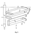
- the device is indicated in its entirety by the reference numeral 1.
- the device comprises a housing 2, in which an upright, cylindrical chamber 3 is arranged.
- two horizontal inlets 4, 5 are connected, each inlet opens into an inflow, which is aligned tangentially (eccentric with respect to the central center axis) in the chamber 3.
- the inlets 4, 5 are at an angle of 90 degrees with respect to each other, extend along the same side of the central axis of the chamber and are at the same height.
- the feeds 4, 5 are intended to be connected to a line system through which, during operation, water or another flowable heating medium having a different temperature is transported.
- the lower end of the chamber 3 is executed flattened conical, the cone merges into a vertical drain 6.
- the drain 6 begins with a discharge part which is substantially axially aligned and lies substantially in the extension of the central center axis of the cylindrical chamber 3.
- an automatically operating Entgasungsabsperrventil 8 is provided at the top of the chamber 3.
- a hand degasser can be provided at the top of the chamber 3.
- the degasser 8 is located substantially upright above the drain 6.
- the circulated heating medium flows eccentrically into the chamber 3 via the two inlets at a fixed speed.
- the two streams of liquid are directed to the left and reinforce each other.
- a strong swirl cyclone
- the gases that are in the liquid, in particular air, are thereby driven into the center of the spin.
- the gases can shift from the center of the chamber 3 to the top of the chamber 3, to be subsequently discharged automatically or manually operated via the degasser 8 to the environment.
- the thus freed of gases liquid leaves the chamber 3 at the bottom of the drain 6.
- the cone ensures this for a gradual breaking off of the liquid flow to the pressure drop there minimize.
- the flow dividing wall 9 ensures that the gases which have been separated from the liquid can come to rest in the chamber 3, whereby the separation of liquid and gas remains.
- the Figures 2-5 show a complex of a heat exchanger 10 a central heating system with a variant of the degassing apparatus 1 described above.
- the heat exchanger 10 comprises a housing 11 in which a part of a conduit system 12 (see FIG. 3 ), which can be heated by means of flue gases released during the combustion of a gas in a burner, which may be provided in the housing 11.
- the line system 12 is partially installed here in the walls of the housing 11.
- the walls of the housing 11 may be made of aluminum, for example.
- the conduit system comprises a feed mouthpiece 13, which merges into a meandering channel 14 with curved pieces and straight pipe parts.
- the channel 14 splits at the top of the heat exchanger (10) into two channels, after which the liquid flows in parallel flow through channels 18, 19 which are installed in a front and rear wall of the housing 11. These channels 18, 19 form cooling channels to cool the uppermost wall portions of the housing 11 of the heat exchanger.
- the cooling channels 18, 19 open into the respective inlets 4, 5 of the degassing device 1.
- the drain 6 of the degassing device 1 connects to a connection mouthpiece 21 of the conduit system 12.
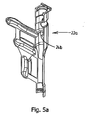
- the housing 2 of the degassing device 1 is installed here in a particularly integrally formed side wall 22 of the housing 11, wherein the degassing device 1 is provided at an angle of the side wall (see FIG. 4 ).
- the inner wall structure of the side wall 22 is in the two cross sections of the FIGS. 5a and b to see in which two mutually connectable side wall parts 22a, 22b are shown. It can also be seen at the same time that in the vicinity a vertical flow dividing wall 24a is provided at the same time with a boundary edge 24b which extends in cross-section and extends inwards.
- This can be advantageously poured during the manufacture of the housing 11 and also serves to allow the gases to come to rest in the chamber above and to escape without liquid on the degasser 8.
- inlets with associated, substantially tangentially oriented inflow parts
- the inlets can be provided at other positions with respect to one another.
- the inlets and / or the inflow parts thereof can be positioned differently, if at all possible, for example if at all possible also oriented obliquely to each other.
- the inlets and inlet channels can merge into one another in one piece or be provided with mouthpieces which can be connected to one another. Instead of a burner can also find another heating element application.
- an efficient and compact and inexpensive to build degassing is provided which degas well both at non-flowing heating media and at high flow rates, whereby in the latter, a centrifugal effect then increases.
- the pressure drop is small and even less than when two or more horizontal inlet channels of a heat exchanger are to come together and with a normal 90 degree bend to go into a common vertical outlet.
Landscapes
- Engineering & Computer Science (AREA)
- Physics & Mathematics (AREA)
- Thermal Sciences (AREA)
- Chemical & Material Sciences (AREA)
- Combustion & Propulsion (AREA)
- Mechanical Engineering (AREA)
- General Engineering & Computer Science (AREA)
- Degasification And Air Bubble Elimination (AREA)
- Steam Or Hot-Water Central Heating Systems (AREA)
- Physical Water Treatments (AREA)
Description
- Die Erfindung bezieht sich auf eine Heizanlage mit einer Entgasungsvorrichtung, insbesondere eine Entlüftungsvorrichtung für eine zentrale Heizanlage.
- Bei dem Installieren und dem Gebrauch von einer zentralen Heizanlage ist eine gute Entlüftung für einen ungestörten Betrieb der Anlage notwendig. Viele bekannte Entlüftungsvorrichtungen, die in zentrale Heizanlagen eingebaut sind, entlüften recht schlecht oder sind voluminös.
- Eine Heizanlage mit einer Entlüftungsvorrichtung ist aus der
NL-A-8603021 - Nachteilig bei dieser bekannten Vorrichtung ist, daß die Entlüftung noch verbesserungswürdig ist und daß der Druckabfall darüber relativ hoch ist. Die Konstruktion mit der Vorkammer hat Krümmungen, in denen Strömungsverluste entstehen. Ferner ist die Vorrichtung zum gleichzeitigen Anschließen an mehrere Kanäle ungeeignet, auch kommt es zu Strömungsverlusten, wenn mehrere Kanäle zu einem Kanal zusammengeführt werden. Viel Druckabfall bedeutet, daß eine starke Pumpe nötig oder mehr Pumpvermögen notwendig ist, um den gewünschten Wasserdurchsatz zu erreichen. Ferner ist die Vorrichtung nicht oder schlecht in der Lage, bei einem stillstehenden Wasserstrom die Luftblasen über den Entlüftungsschwimmer an die Umgebung abzuführen.
- Eine Heizanlage nach dem Oberbegriff von Anspruch 1 ist aus der
US 5,829,677 bekannt. Die Entlüftungsvorrichtung von dieser Heizanlage umfasst hierbei eine Gehäuse mit einer verticalen zylindrischen Kammer mit zwei tangential ausgerichteten Zuläufen und ein tangentialen Ablauf, sowie einem Entlüftungsabsperrventil, um Gase aus dem Gehäuse abzuführen. Einer der zwei Zuläufe von dieser Entgasungsvorrichtung ist dabei angeschlossen an einen Ablaufkanal eines Leitungssystems stromaufwärts von einem Wärmetauscher, weil der andere der zwei Zuläufen ist angeschlossen an einem Bypasskanal das abzweigt von einem Zufuhrkanal des Leitungssystems stromabwärts von dem genannten Wärmetauscher. - Die vorliegende Erfindung hat zum Ziel, die oben genannten Nachteile zumindest teilweise zu beseitigen oder eine brauchbare Alternative bereitzustellen. Insbesondere hat die Erfindung zum Ziel, eine Heizanlage mit einer Entgasungsvorrichtung bereitzustellen, die bei geringen Abmessungen und geringem Druckabfall eine gute Entgasung herbeiführen kann.
- Dieses Ziel wird durch eine Heizanlage mit einem Wärmetauscher und einer an ein Leitungssystem angeschlossen Entgasungsvorrichtung gemäß dem Anspruch 1 erreicht. Gemäss das kennzeichnende Teil der Erfindung ist das Gehäuse der Entgasungsvorrichtung in eine Seitenwand des Gehäuses des Wärmetauschers eingebaut. Die Entgasungsvorrichtung umfaßt hierbei ein Gehäuse mit einer im wesentlichen vertikal ausgerichteten, zylindrischen Kammer mit mindestens zwei im wesentlichen tangential ausgerichteten Zuläufen und einem Ablauf zum Anschließen an ein Leitungssystem, sowie einem Entlüftungsabsperrventil, um Gase aus dem Gehäuse abzuführen. Die Zuläufe sind dazu bestimmt, mit einem Ablaufkanal des Leitungssystems in Strömungsverbindung zu stehen oder gebracht zu werden. Die Zuläufe sorgen während des Betriebs für ein exzentrisches Einströmen von Flüssigkeit. Hierdurch entsteht ein Zyklon, wobei sich Gase aus der Flüssigkeit in das Zentrum der Kammer verlagern. Die Gase können danach über das Entgasungsabsperrventil aus dem Flüssigkeitskreislauf abgeführt werden. Dies ist folglich mit dem Vorteil verbunden, daß mindestens zwei im wesentlichen tangential in einer Entgasungskammer ausgerichtete eingehende Flüssigkeitsströme bei einem geringen Druckabfall und einer sehr guten Entgasung zu einem Ablaufkanal zusammengeführt werden können. In einer besonderen Ausführungsform münden die Zuläufe in im wesentlichen derselben Höhe in die Kammer. Diese Aufstellung sorgt dafür, daß sich die Flüssigkeiten gut miteinander vermengen, zusammen schraubenlinienförmig nach unten strömen und einen Zyklon bilden. Hierdurch entsteht vorteilhaft eine noch bessere Entgasung.
- In einer weiteren Ausführungsform ist der eine Zulauf in einem Winkel von im wesentlichen 90 Grad verdreht entlang dem Wandumfang der Kammer in Bezug auf den anderen Zulauf vorgesehen. Auch hierdurch entsteht der Effekt von mehreren hereinkommenden Flüssigkeiten, die sich gut miteinander vermengen und einen gemeinsamen Zyklon bilden. Zugleich macht dieser Aufbau die Anordnung der Entgasungsvorrichtung in einem Aufbau mit zwei unter einem im wesentlichen senkrechten Winkel in Bezug zueinander stehenden Zulaufkanälen möglich, ohne daß dabei unnötige Druckverluste auftreten.
- Das Ziel gemäß der Erfindung kann zugleich durch eine Entgasungsvorrichtung gemäß dem Anspruch 4 erreicht werden. Der Ablauf ist im wesentlichen axial ausgerichtet und schließt an dem unteren Ende der Kammer an. Hierdurch wird vorteilhaft ein geringer Druckabfall in der Entgasungsvorrichtung erreicht, insbesondere indem sich das untere Ende der Kammer nach und nach vom Durchmesser her verjüngt, der in den Ablauf übergeht. Durch den im wesentlichen axial ausgerichteten Ablauf können bei einem stillstehenden oder langsamen Flüssigkeitsstrom Gasblasen ungestört durch die Kammer aufsteigen und über das Entgasungsabsperrventil entweichen. Die Entgasungsvorrichtung kann hierdurch sowohl während des Transports der Flüssigkeit hindurch als auch bei zeitweiligem Stillstand der Flüssigkeit darin gut und wirksam entgasen, was eine noch bessere Entgasungsleistung bewirkt.
- In einer Variante kann der Ablauf auch im wesentlichen tangential ausgerichtet sein und an die Umfangswand der Kammer anschließen. Vorteil des exzentrischen Ablaufs ist hierbei ein geringer Druckabfall.
- Weitere vorteilhafte Ausführungsformen sind in den Unteransprüchen festgelegt.
- Die Erfindung wird anhand der beigefügten Zeichnung näher erläutert werden, worin:
- Figur 1
- eine schematische perspektivische Darstellung einer Ausführungsform der erfindungsgemäßen Entgasungsvorrichtung zeigt;
- Figur 2
- eine schematische perspektivische Darstellung eines Komplexes aus einer Variante der Entgasungsvorrichtung mit einem Wärmetauscher zeigt;
- Figur 3
- schematisch das Leitungssystem zeigt, an dem die Entgasungsvorrichtung gemäß der
Fig. 2 ohne Gehäuse angeschlossen ist; - Figur 4
- die Seitenwand mit der darin integrierten Entgasungsvorrichtung gemäß der
Fig. 2 zeigt; und - Figuren 5a und 5b
- eine Querschnitt durch die Seitenwand gemäß der
Fig. 4 aus entgegengesetzten Richtungen zeigen. - In der
Figur 1 ist die Vorrichtung in ihrem Ganzen mit der Bezugsziffer 1 angedeutet. Die Vorrichtung umfaßt ein Gehäuse 2, in dem eine aufrecht stehende, zylindrische Kammer 3 angeordnet ist. An der Kammer 3 sind zwei horizontale Zuläufe 4, 5 angeschlossen, wobei jeder Zulauf in ein Einströmteil mündet, welches tangential (exzentrisch in Bezug auf die zentrale Mittelachse) in der Kammer 3 ausgerichtet ist. Die Zuläufe 4, 5 stehen unter einem Winkel von 90 Grad in Bezug zueinander, erstrecken sich entlang der gleichen Seite der Mittelachse der Kammer und befinden sich auf der gleichen Höhe. Die Zuläufe 4, 5 sind dazu bestimmt, an ein Leitungssystem angeschlossen zu werden, durch welches während des Betriebs Wasser oder ein anderes fließfähiges Heizmedium mit einer unterschiedlichen Temperatur transportiert wird. Das untere Ende der Kammer 3 ist abgeflacht kegelförmig ausgeführt, dessen Konus in einen vertikalen Ablauf 6 übergeht. Der Ablauf 6 beginnt mit einem Ausströmteil, das im wesentlichen axial ausgerichtet ist und im wesentlichen in der Verlängerung der zentralen Mittelachse der zylindrischen Kammer 3 liegt. An der Oberseite der Kammer 3 ist ein automatisch arbeitendes Entgasungsabsperrventil 8 vorgesehen. In einer Variante kann auch ein Handentgaser vorgesehen sein. Der Entgaser 8 befindet sich im wesentlichen aufrecht oberhalb des Ablaufs 6. Oben in der Kammer 3 unterhalb des Entgasers 8 befindet sich eine Strömungstrennwand 9. - Während des Betriebs strömt das im Umlauf transportierte Heizmedium über die beiden Zuläufe mit einer festgelegten Geschwindigkeit exzentrisch in die Kammer 3 hinein. Die beiden Flüssigkeitsströme sind links herum gerichtet und verstärken einander. Hierdurch wird ein starker Drehstrudel (Zyklon) gebildet, wobei die Flüssigkeit schraubenlinienförmig entlang der Kammerwand nach unten strömt. Die Gase, die sich in der Flüssigkeit befinden, insbesondere Luft, werden hierbei in die Mitte des Drehstrudels getrieben. Die Gase können sich aus dem Zentrum der Kammer 3 zur Oberseite der Kammer 3 verlagern, um anschließend automatisch oder handbetätigt über den Entgaser 8 an die Umgebung abgeführt zu werden. Die folglich von Gasen befreite Flüssigkeit verläßt die Kammer 3 an der Unterseite über den Ablauf 6. Der Konus sorgt hierbei für ein allmähliches Abbrechen des Flüssigkeitsstroms, um den Druckabfall dort zu minimieren. Die Strömungstrennwand 9 sorgt dafür, daß die Gase, die von der Flüssigkeit abgeschieden wurden, in der Kammer 3 zur Ruhe kommen können, wobei die Abscheidung von Flüssigkeit und Gas bestehen bleibt.
- Die
Figuren 2-5 zeigen einen Komplex aus einem Wärmetauscher 10 einer zentralen Heizanlage mit einer Variante der oben beschriebenen Entgasungsvorrichtung 1. Der Wärmetauscher 10 umfaßt ein Gehäuse 11, in dem ein Teil eines Leitungssystems 12 (sieheFigur 3 ) angeordnet ist, das mit Hilfe von Rauchgasen erwärmt werden kann, die bei der Verbrennung eines Gases in einem Brenner, welcher in dem Gehäuse 11 vorgesehen sein kann, freigesetzt werden. Das Leitungssystem 12 ist hier teilweise in die Wände des Gehäuses 11 eingebaut. Die Wände des Gehäuses 11 können beispielsweise aus Aluminium gefertigt sein. Das Leitungssystem umfaßt ein Zulaufmundstück 13, das in einen mäanderförmigen Kanal 14 mit gebogenen Stücken und geraden Rohrteilen übergeht. Der Kanal 14 teilt sich an dem Oberteil des Wärmetauscher (10) in zwei Kanäle, wonach die Flüssigkeit im Parallelstrom durch Kanäle 18, 19 strömt, die in einer Vorder- und Rückwand des Gehäuses 11 eingebaut sind. Diese Kanäle 18, 19 bilden Kühlkanäle, um die obersten Wandteile des Gehäuses 11 des Wärmetauschers zu kühlen. Die Kühlkanäle 18, 19 münden in die jeweiligen Zuläufe 4, 5 der Entgasungsvorrichtung 1. Der Ablauf 6 der Entgasungsvorrichtung 1 schließt an ein Anschlußmundstück 21 des Leitungssystems 12 an. - Das Gehäuse 2 der Entgasungsvorrichtung 1 ist hier in eine insbesondere einteilig ausgeführte Seitenwand 22 des Gehäuses 11 eingebaut, wobei die Entgasungsvorrichtung 1 an einem Winkel der Seitenwand vorgesehen ist ( siehe
Figur 4 ). Der innenwandige Aufbau der Seitenwand 22 ist in den beiden Querschnitten von denFiguren 5a undb zu sehen, worin zwei aneinander anschließbare Seitenwandteile 22a, 22b gezeigt sind. Hierin ist zugleich zu sehen, daß in der Nähe eine vertikal aufgestellte Strömungstrennwand 24a nun zugleich mit einem im Querschnitt rundlaufenden, sich nach innen erstreckenden Begrenzungsrand 24b versehen ist. Dieser kann vorteilhafter Weise während der Herstellung des Gehäuses 11 gegossen werden und dient gleichfalls dazu, die Gase oben in der Kammer zur Ruhe kommen zu lassen und ohne Flüssigkeit über den Entgaser 8 entweichen zu lassen. - Neben den gezeigten Ausführungsformen sind viele Varianten möglich. So können beispielsweise mehr als zwei Zuläufe mit zugehörigen, im wesentlichen tangential ausgerichteten Einströmteilen vorgesehen werden und können die Zuläufe an anderen Positionen in Bezug zueinander vorgesehen sein. Auch können die Zuläufe und/oder die Einströmteile davon wenn irgend möglich anders positioniert werden, beispielsweise wenn irgend möglich auch schräg zueinander ausgerichtet sein. Die Zuläufe und Zulaufkanäle können einteilig ineinander übergehen oder mit miteinander verbindbaren Mundstücken versehen sein. Anstelle eines Brenners kann auch ein anderes Heizelement Anwendung finden.
- Folglich wird gemäß der Erfindung eine wirksam arbeitende und kompakte und preiswert zu bauende Entgasungsvorrichtung bereitgestellt, die sowohl bei nicht strömenden Heizmedien als auch bei großen Strömungsgeschwindigkeiten gut entgast, wodurch bei dem letztgenannten ein Zentrifugeneffekt dann zunimmt. Der Druckabfall ist gering und sogar geringer als wenn zwei oder mehrere horizontale Zulaufkanäle eines Wärmetauschers zusammen kommen sollen und mit einer normalen 90 Grad Biegung in einen gemeinsamen vertikalen Ablauf übergehen sollen.
Claims (14)
- Heizanl.age mit einem Wärmetauscher (10) und einer an ein Leitungssystem (12) angeschlossenen Entgasungsvorrichtung (1), in welcher Leitungssystem (12) eine Flüssigkeit mit unterschiedlicher Temperatur transportierbar ist,
wobei die Entgasungsvorrichtung (1) umfasst.:- ein Gehäuse (2) mit einer im wesentlichen zylindrischen Kammer (3);- mindestens einem Zulauf (4, 5) und einem Ablauf (6) um die Kammer (3) an das Leitungssystem (12) anzuschließen; und- einem Entgasungsabsperrventil (8), um Gase aus dem Gehäuse (2) abzuführen,wobei die Kammer (3) im wesentlichen vertikal ausgerichtet ist, wobei mindestens zwei Zuläufe (4, 5) zum Anschließen an das Leitungssystem vorgesehen sind, wobei die Zuläufe jeweils im wesentlichen tangential in der Kammer (3) ausgerichtet sind und das Entgasungssperrventil (8) an der Oberseite der Kammer (3) vorgesehen ist,
wobei der Wärmetauscher (10) umfasst:ein Gehäuse (11), in dem ein Heizelement, und einem Teil des Leitungssystems (12) mit Zu- und Ablaufkanälen (13, 14, 18, 19, 21) angeordnet sind,wobei die Zu- und Ablaufkanäle (13, 14,18, 19, 21) an den jeweiligen Zu- und Abläufen (4, 5, 6) der Entgasungsvorrichtung (1) angeschlossen sind,dadurch gekennzeichnet, daßdas Gehäuse (2) der Entgasungsvorrichtung (1) in eine Seitenwand (22) des Gehäuses (11) des Wärmetauschers (10) eingebaut ist. - Heizanlage nach Anspruch 1, dadurch gekennzeichnet, daß die Zuläufe (4, 5) auf im wesentlichen der gleichen Höhe in die Kammer (3) münden.
- Heizanlage nach Anspruch 1 oder 2, dadurch gekennzeichnet, daß der eine Zulauf (4) um einen Winkel von im wesentlichen um 90 Grad verdreht entlang der Umfangswand der Kammer (3) im Bezug auf den anderen Zulauf (5) vorgesehen ist.
- Heizanlage nach einem der Ansprüche 1-3, dadurch gekennzeichnet, daß
der Ablauf (6) im wesentlichen axial ausgerichtet ist und in dem unteren Ende der Kammer (3) angeordnet ist. - Heizanlage nach Anspruch 4, dadurch gekennzeichnet, daß das untere Ende der Kammer (3) sich nach und nach zu einem kleineren Durchmesser verjüngt.
- Heizanlage nach Anspruch 4 oder 5, dadurch gekennzeichnet, daß der Ablauf (6) und das Entgasungsabsperrventil (8) im wesentlichen aufrecht übereinander vorgesehen sind.
- Heizanlage nach einem der Ansprüche 1-3, dadurch gekennzeichnet, daß der Ablauf (6) im wesentlichen tangential ausgerichtet ist und an die Umfangswand der Kammer (3) anschließt.
- Heizanlage nach einem der vorhergehenden Ansprüche, dadurch gekennzeichnet, daß oberhalb der Zuläufe (4, 5) ein Begrenzungsmittel (9) für den Flüssigkeitsstrom in der Kammer (3) vorgesehen ist.
- Heizanlage nach Anspruch 8, dadurch gekennzeichnet, daß das Begrenzungsmittel (9) ein sich nach innen in die Kammer (3) erstreckendes Wandteil ist.
- Heizanlage nach einem der vorhergehenden Ansprüche, dadurch gekennzeichnet, daß die Zu- und Ablaufkanäle (13, 14, 18, 19, 21) zumindest teilweise in die Seitenwände (16, 17, 22) des Gehäuses (11) des Wärmetauschers (10) eingebaut sind.
- Heizanlage nach einem der vorhergehende Ansprüche, dadurch gekennzeichnet, dass die Zu-und Ablaufkanäle mit einen Zulaufmundstück (13) starten das in einen einzelnen Kanal (14) ubergeht das (13, 14) sich in zwei Kanäle (18, 19) teilt, welche Kanäle (18, 19) in die jeweiligen zwei Zuläufe (4,5) der Entgasungsvorrichtung (1) münden.
- Heizanlage nach Anspruch 11, dadurch gekennzeichnet, daß die zwei Kanäle (18, 19) in einer Vorder- und Rückwand des Gehäuses (11) eingebaut sind.
- Heizanlage nach Anspruch 11 oder 12, dadurch gekenzeichnet, daß die zwei Kanäle (18, 19) in einem Oberteil des Wärmetauschers (10) angeordnet sind.
- Heizanlage nach einem der Anssprüche 11-13, dadurch gekenzeichnet, daß die zwei. Kanäle (18, 19) parallel angeordnet sind.
Applications Claiming Priority (2)
| Application Number | Priority Date | Filing Date | Title |
|---|---|---|---|
| NL1025415A NL1025415C2 (nl) | 2004-02-05 | 2004-02-05 | Ontgassingsinrichting. |
| NL1025415 | 2004-02-05 |
Publications (2)
| Publication Number | Publication Date |
|---|---|
| EP1562001A1 EP1562001A1 (de) | 2005-08-10 |
| EP1562001B1 true EP1562001B1 (de) | 2012-03-28 |
Family
ID=34676045
Family Applications (1)
| Application Number | Title | Priority Date | Filing Date |
|---|---|---|---|
| EP05075217A Expired - Lifetime EP1562001B1 (de) | 2004-02-05 | 2005-01-27 | Heizanlage mit Entgasungsvorrichtung |
Country Status (3)
| Country | Link |
|---|---|
| EP (1) | EP1562001B1 (de) |
| AT (1) | ATE551574T1 (de) |
| NL (1) | NL1025415C2 (de) |
Cited By (1)
| Publication number | Priority date | Publication date | Assignee | Title |
|---|---|---|---|---|
| EP4498003A1 (de) * | 2023-07-27 | 2025-01-29 | Vaillant GmbH | Gasleckagebewältigung |
Families Citing this family (4)
| Publication number | Priority date | Publication date | Assignee | Title |
|---|---|---|---|---|
| WO2008071943A1 (en) * | 2006-12-13 | 2008-06-19 | Stanley Whetstone | Fluid containment and transfer vessel |
| GB2520680B (en) * | 2013-11-27 | 2018-07-25 | Bisset James | A central heating system device |
| NL2023920B1 (en) * | 2019-09-30 | 2020-07-14 | Flamco Bv | Removal device with flow control |
| EP4506626B1 (de) * | 2023-08-07 | 2026-01-21 | Vaillant GmbH | Entgasungsvorrichtung |
Family Cites Families (3)
| Publication number | Priority date | Publication date | Assignee | Title |
|---|---|---|---|---|
| NL106105C (de) * | 1900-01-01 | |||
| NL8603021A (nl) | 1986-11-27 | 1988-06-16 | Nefit Nv | Inrichting voor het ontluchten van een in een leidingstelsel circulerende vloeistof. |
| US5738277A (en) * | 1996-08-12 | 1998-04-14 | Systecon, Inc. | Water heating and cooling system having a dual water mixing and air separator apparatus |
-
2004
- 2004-02-05 NL NL1025415A patent/NL1025415C2/nl not_active IP Right Cessation
-
2005
- 2005-01-27 EP EP05075217A patent/EP1562001B1/de not_active Expired - Lifetime
- 2005-01-27 AT AT05075217T patent/ATE551574T1/de active
Cited By (1)
| Publication number | Priority date | Publication date | Assignee | Title |
|---|---|---|---|---|
| EP4498003A1 (de) * | 2023-07-27 | 2025-01-29 | Vaillant GmbH | Gasleckagebewältigung |
Also Published As
| Publication number | Publication date |
|---|---|
| ATE551574T1 (de) | 2012-04-15 |
| EP1562001A1 (de) | 2005-08-10 |
| NL1025415C2 (nl) | 2005-08-08 |
Similar Documents
| Publication | Publication Date | Title |
|---|---|---|
| EP2178624B1 (de) | Vorrichtung für die anreicherung eines flüssigkeitsstroms mit einem gas | |
| DE3419305A1 (de) | Verfahren und vorrichtung zum vermindern des gasgehaltes einer fluessigkeit | |
| EP3156659B1 (de) | Pumpenaggregat und hydraulisches system | |
| DE102010051638A1 (de) | Gasturbinenbrennkammer mit einer Kühlluftzuführvorrichtung | |
| EP0550510B1 (de) | Belüftungsdüse zum belüften von organische substanzen enthaltenden flüssigkeiten | |
| DE102007032228B4 (de) | Selbstansaugende Pumpenaggregation | |
| EP1562001B1 (de) | Heizanlage mit Entgasungsvorrichtung | |
| DE69429451T2 (de) | Selbstansaugende kreiselpumpe | |
| DE19822704B4 (de) | Gasabscheidende Brauchwasser-Zirkulationspumpe | |
| EP3348804B1 (de) | Schmiermittelbehälter für ein hydrauliksystem | |
| DE2948674A1 (de) | Vorrichtung und verfahren zum entgasen einer fluessigkeit | |
| DE112024000583T5 (de) | Gebläse | |
| CN1090983C (zh) | 将混成分散系的液-液萃取两种溶液可控地导入分离部的方法和设备 | |
| WO2020083921A1 (de) | Kontinuierlich arbeitende und fluidatmende fluidmischeinrichtung und verfahren zum betrieb einer solchen | |
| EP3364043B1 (de) | Pumpenaggregat mit integrierter entlüftung- und entleerungseinheit | |
| DE102014221203A1 (de) | Strahlpumpe | |
| DE102008022279B4 (de) | Strahlpumpe und Verfahren zum Betrieb einer Strahlpumpe | |
| EP3135879B1 (de) | Bypass-einrichtung zur reduzierung einer rezirkulation erwärmter luft in eine kühleinrichtung | |
| DE102008021761A1 (de) | Verfahren zum Betreiben einer Anordnung von Wärmetauschern und hierfür geeignete Vorrichtung | |
| EP2072823B1 (de) | Kreiselpumpe mit Entlüftung | |
| AT413871B (de) | Einrichtung zum regeln der fördermenge von rotationsverdichtern | |
| DE1503523A1 (de) | Verbesserungen an Geblaesen | |
| DE60124150T2 (de) | Luftauslasseinheit für grosse gebläseanordnung | |
| EP1188930B1 (de) | Gebläseanordnung, insbesondere Radialgebläseanordnung | |
| DE10033154C2 (de) | Schraubenverdichteranlage |
Legal Events
| Date | Code | Title | Description |
|---|---|---|---|
| PUAI | Public reference made under article 153(3) epc to a published international application that has entered the european phase |
Free format text: ORIGINAL CODE: 0009012 |
|
| AK | Designated contracting states |
Kind code of ref document: A1 Designated state(s): AT BE BG CH CY CZ DE DK EE ES FI FR GB GR HU IE IS IT LI LT LU MC NL PL PT RO SE SI SK TR |
|
| AX | Request for extension of the european patent |
Extension state: AL BA HR LV MK YU |
|
| 17P | Request for examination filed |
Effective date: 20060125 |
|
| AKX | Designation fees paid |
Designated state(s): AT BE BG CH CY CZ DE DK EE ES FI FR GB GR HU IE IS IT LI LT LU MC NL PL PT RO SE SI SK TR |
|
| 17Q | First examination report despatched |
Effective date: 20100119 |
|
| GRAP | Despatch of communication of intention to grant a patent |
Free format text: ORIGINAL CODE: EPIDOSNIGR1 |
|
| RTI1 | Title (correction) |
Free format text: HEATING WITH VENTING APPARATUS |
|
| GRAS | Grant fee paid |
Free format text: ORIGINAL CODE: EPIDOSNIGR3 |
|
| GRAA | (expected) grant |
Free format text: ORIGINAL CODE: 0009210 |
|
| AK | Designated contracting states |
Kind code of ref document: B1 Designated state(s): AT BE BG CH CY CZ DE DK EE ES FI FR GB GR HU IE IS IT LI LT LU MC NL PL PT RO SE SI SK TR |
|
| REG | Reference to a national code |
Ref country code: GB Ref legal event code: FG4D Free format text: NOT ENGLISH |
|
| REG | Reference to a national code |
Ref country code: CH Ref legal event code: EP |
|
| REG | Reference to a national code |
Ref country code: AT Ref legal event code: REF Ref document number: 551574 Country of ref document: AT Kind code of ref document: T Effective date: 20120415 |
|
| REG | Reference to a national code |
Ref country code: IE Ref legal event code: FG4D Free format text: LANGUAGE OF EP DOCUMENT: GERMAN |
|
| REG | Reference to a national code |
Ref country code: DE Ref legal event code: R096 Ref document number: 502005012573 Country of ref document: DE Effective date: 20120524 |
|
| REG | Reference to a national code |
Ref country code: NL Ref legal event code: T3 |
|
| REG | Reference to a national code |
Ref country code: CH Ref legal event code: NV Representative=s name: FIAMMENGHI-FIAMMENGHI |
|
| PG25 | Lapsed in a contracting state [announced via postgrant information from national office to epo] |
Ref country code: LT Free format text: LAPSE BECAUSE OF FAILURE TO SUBMIT A TRANSLATION OF THE DESCRIPTION OR TO PAY THE FEE WITHIN THE PRESCRIBED TIME-LIMIT Effective date: 20120328 |
|
| LTIE | Lt: invalidation of european patent or patent extension |
Effective date: 20120328 |
|
| PG25 | Lapsed in a contracting state [announced via postgrant information from national office to epo] |
Ref country code: GR Free format text: LAPSE BECAUSE OF FAILURE TO SUBMIT A TRANSLATION OF THE DESCRIPTION OR TO PAY THE FEE WITHIN THE PRESCRIBED TIME-LIMIT Effective date: 20120629 Ref country code: FI Free format text: LAPSE BECAUSE OF FAILURE TO SUBMIT A TRANSLATION OF THE DESCRIPTION OR TO PAY THE FEE WITHIN THE PRESCRIBED TIME-LIMIT Effective date: 20120328 |
|
| PG25 | Lapsed in a contracting state [announced via postgrant information from national office to epo] |
Ref country code: CY Free format text: LAPSE BECAUSE OF FAILURE TO SUBMIT A TRANSLATION OF THE DESCRIPTION OR TO PAY THE FEE WITHIN THE PRESCRIBED TIME-LIMIT Effective date: 20120328 |
|
| PG25 | Lapsed in a contracting state [announced via postgrant information from national office to epo] |
Ref country code: SE Free format text: LAPSE BECAUSE OF FAILURE TO SUBMIT A TRANSLATION OF THE DESCRIPTION OR TO PAY THE FEE WITHIN THE PRESCRIBED TIME-LIMIT Effective date: 20120328 Ref country code: SI Free format text: LAPSE BECAUSE OF FAILURE TO SUBMIT A TRANSLATION OF THE DESCRIPTION OR TO PAY THE FEE WITHIN THE PRESCRIBED TIME-LIMIT Effective date: 20120328 Ref country code: IS Free format text: LAPSE BECAUSE OF FAILURE TO SUBMIT A TRANSLATION OF THE DESCRIPTION OR TO PAY THE FEE WITHIN THE PRESCRIBED TIME-LIMIT Effective date: 20120728 Ref country code: RO Free format text: LAPSE BECAUSE OF FAILURE TO SUBMIT A TRANSLATION OF THE DESCRIPTION OR TO PAY THE FEE WITHIN THE PRESCRIBED TIME-LIMIT Effective date: 20120328 Ref country code: PL Free format text: LAPSE BECAUSE OF FAILURE TO SUBMIT A TRANSLATION OF THE DESCRIPTION OR TO PAY THE FEE WITHIN THE PRESCRIBED TIME-LIMIT Effective date: 20120328 Ref country code: CZ Free format text: LAPSE BECAUSE OF FAILURE TO SUBMIT A TRANSLATION OF THE DESCRIPTION OR TO PAY THE FEE WITHIN THE PRESCRIBED TIME-LIMIT Effective date: 20120328 Ref country code: EE Free format text: LAPSE BECAUSE OF FAILURE TO SUBMIT A TRANSLATION OF THE DESCRIPTION OR TO PAY THE FEE WITHIN THE PRESCRIBED TIME-LIMIT Effective date: 20120328 |
|
| PG25 | Lapsed in a contracting state [announced via postgrant information from national office to epo] |
Ref country code: SK Free format text: LAPSE BECAUSE OF FAILURE TO SUBMIT A TRANSLATION OF THE DESCRIPTION OR TO PAY THE FEE WITHIN THE PRESCRIBED TIME-LIMIT Effective date: 20120328 Ref country code: PT Free format text: LAPSE BECAUSE OF FAILURE TO SUBMIT A TRANSLATION OF THE DESCRIPTION OR TO PAY THE FEE WITHIN THE PRESCRIBED TIME-LIMIT Effective date: 20120730 |
|
| PG25 | Lapsed in a contracting state [announced via postgrant information from national office to epo] |
Ref country code: DK Free format text: LAPSE BECAUSE OF FAILURE TO SUBMIT A TRANSLATION OF THE DESCRIPTION OR TO PAY THE FEE WITHIN THE PRESCRIBED TIME-LIMIT Effective date: 20120328 |
|
| PLBE | No opposition filed within time limit |
Free format text: ORIGINAL CODE: 0009261 |
|
| STAA | Information on the status of an ep patent application or granted ep patent |
Free format text: STATUS: NO OPPOSITION FILED WITHIN TIME LIMIT |
|
| 26N | No opposition filed |
Effective date: 20130103 |
|
| REG | Reference to a national code |
Ref country code: DE Ref legal event code: R097 Ref document number: 502005012573 Country of ref document: DE Effective date: 20130103 |
|
| PG25 | Lapsed in a contracting state [announced via postgrant information from national office to epo] |
Ref country code: ES Free format text: LAPSE BECAUSE OF FAILURE TO SUBMIT A TRANSLATION OF THE DESCRIPTION OR TO PAY THE FEE WITHIN THE PRESCRIBED TIME-LIMIT Effective date: 20120709 |
|
| PG25 | Lapsed in a contracting state [announced via postgrant information from national office to epo] |
Ref country code: BG Free format text: LAPSE BECAUSE OF FAILURE TO SUBMIT A TRANSLATION OF THE DESCRIPTION OR TO PAY THE FEE WITHIN THE PRESCRIBED TIME-LIMIT Effective date: 20120628 |
|
| PG25 | Lapsed in a contracting state [announced via postgrant information from national office to epo] |
Ref country code: MC Free format text: LAPSE BECAUSE OF NON-PAYMENT OF DUE FEES Effective date: 20130131 |
|
| REG | Reference to a national code |
Ref country code: IE Ref legal event code: MM4A |
|
| PG25 | Lapsed in a contracting state [announced via postgrant information from national office to epo] |
Ref country code: IE Free format text: LAPSE BECAUSE OF NON-PAYMENT OF DUE FEES Effective date: 20130127 |
|
| REG | Reference to a national code |
Ref country code: FR Ref legal event code: PLFP Year of fee payment: 11 |
|
| PG25 | Lapsed in a contracting state [announced via postgrant information from national office to epo] |
Ref country code: TR Free format text: LAPSE BECAUSE OF FAILURE TO SUBMIT A TRANSLATION OF THE DESCRIPTION OR TO PAY THE FEE WITHIN THE PRESCRIBED TIME-LIMIT Effective date: 20120328 |
|
| PG25 | Lapsed in a contracting state [announced via postgrant information from national office to epo] |
Ref country code: LU Free format text: LAPSE BECAUSE OF NON-PAYMENT OF DUE FEES Effective date: 20130127 Ref country code: HU Free format text: LAPSE BECAUSE OF FAILURE TO SUBMIT A TRANSLATION OF THE DESCRIPTION OR TO PAY THE FEE WITHIN THE PRESCRIBED TIME-LIMIT; INVALID AB INITIO Effective date: 20050127 |
|
| REG | Reference to a national code |
Ref country code: FR Ref legal event code: PLFP Year of fee payment: 12 |
|
| PGFP | Annual fee paid to national office [announced via postgrant information from national office to epo] |
Ref country code: CH Payment date: 20160121 Year of fee payment: 12 Ref country code: IT Payment date: 20160122 Year of fee payment: 12 |
|
| PGFP | Annual fee paid to national office [announced via postgrant information from national office to epo] |
Ref country code: BE Payment date: 20160121 Year of fee payment: 12 Ref country code: AT Payment date: 20160120 Year of fee payment: 12 |
|
| REG | Reference to a national code |
Ref country code: FR Ref legal event code: PLFP Year of fee payment: 13 |
|
| PG25 | Lapsed in a contracting state [announced via postgrant information from national office to epo] |
Ref country code: BE Free format text: LAPSE BECAUSE OF NON-PAYMENT OF DUE FEES Effective date: 20170131 |
|
| REG | Reference to a national code |
Ref country code: CH Ref legal event code: PL |
|
| REG | Reference to a national code |
Ref country code: AT Ref legal event code: MM01 Ref document number: 551574 Country of ref document: AT Kind code of ref document: T Effective date: 20170127 |
|
| PG25 | Lapsed in a contracting state [announced via postgrant information from national office to epo] |
Ref country code: LI Free format text: LAPSE BECAUSE OF NON-PAYMENT OF DUE FEES Effective date: 20170131 Ref country code: AT Free format text: LAPSE BECAUSE OF NON-PAYMENT OF DUE FEES Effective date: 20170127 Ref country code: CH Free format text: LAPSE BECAUSE OF NON-PAYMENT OF DUE FEES Effective date: 20170131 |
|
| REG | Reference to a national code |
Ref country code: FR Ref legal event code: PLFP Year of fee payment: 14 |
|
| REG | Reference to a national code |
Ref country code: BE Ref legal event code: MM Effective date: 20170131 |
|
| PG25 | Lapsed in a contracting state [announced via postgrant information from national office to epo] |
Ref country code: IT Free format text: LAPSE BECAUSE OF NON-PAYMENT OF DUE FEES Effective date: 20170127 |
|
| PGFP | Annual fee paid to national office [announced via postgrant information from national office to epo] |
Ref country code: NL Payment date: 20180124 Year of fee payment: 14 |
|
| REG | Reference to a national code |
Ref country code: DE Ref legal event code: R084 Ref document number: 502005012573 Country of ref document: DE |
|
| PGFP | Annual fee paid to national office [announced via postgrant information from national office to epo] |
Ref country code: GB Payment date: 20180125 Year of fee payment: 14 Ref country code: DE Payment date: 20180308 Year of fee payment: 14 |
|
| PGFP | Annual fee paid to national office [announced via postgrant information from national office to epo] |
Ref country code: FR Payment date: 20180124 Year of fee payment: 14 |
|
| REG | Reference to a national code |
Ref country code: DE Ref legal event code: R119 Ref document number: 502005012573 Country of ref document: DE |
|
| REG | Reference to a national code |
Ref country code: NL Ref legal event code: MM Effective date: 20190201 |
|
| GBPC | Gb: european patent ceased through non-payment of renewal fee |
Effective date: 20190127 |
|
| PG25 | Lapsed in a contracting state [announced via postgrant information from national office to epo] |
Ref country code: NL Free format text: LAPSE BECAUSE OF NON-PAYMENT OF DUE FEES Effective date: 20190201 Ref country code: FR Free format text: LAPSE BECAUSE OF NON-PAYMENT OF DUE FEES Effective date: 20190131 Ref country code: DE Free format text: LAPSE BECAUSE OF NON-PAYMENT OF DUE FEES Effective date: 20190801 |
|
| PG25 | Lapsed in a contracting state [announced via postgrant information from national office to epo] |
Ref country code: GB Free format text: LAPSE BECAUSE OF NON-PAYMENT OF DUE FEES Effective date: 20190127 |