EP1562001A1 - Entgasungsvorrichtung - Google Patents
Entgasungsvorrichtung Download PDFInfo
- Publication number
- EP1562001A1 EP1562001A1 EP05075217A EP05075217A EP1562001A1 EP 1562001 A1 EP1562001 A1 EP 1562001A1 EP 05075217 A EP05075217 A EP 05075217A EP 05075217 A EP05075217 A EP 05075217A EP 1562001 A1 EP1562001 A1 EP 1562001A1
- Authority
- EP
- European Patent Office
- Prior art keywords
- chamber
- degassing device
- housing
- degassing
- inlet
- Prior art date
- Legal status (The legal status is an assumption and is not a legal conclusion. Google has not performed a legal analysis and makes no representation as to the accuracy of the status listed.)
- Granted
Links
- 238000013022 venting Methods 0.000 title description 2
- 238000007872 degassing Methods 0.000 claims abstract description 50
- 239000007788 liquid Substances 0.000 claims abstract description 21
- 239000007789 gas Substances 0.000 claims abstract description 15
- 238000010438 heat treatment Methods 0.000 claims abstract description 15
- 230000002093 peripheral effect Effects 0.000 claims description 3
- 238000000034 method Methods 0.000 description 8
- XLYOFNOQVPJJNP-UHFFFAOYSA-N water Substances O XLYOFNOQVPJJNP-UHFFFAOYSA-N 0.000 description 7
- 239000012530 fluid Substances 0.000 description 5
- 230000000694 effects Effects 0.000 description 4
- 238000009423 ventilation Methods 0.000 description 4
- 238000004891 communication Methods 0.000 description 2
- 238000010276 construction Methods 0.000 description 2
- 238000001816 cooling Methods 0.000 description 2
- 238000005192 partition Methods 0.000 description 2
- 241001156002 Anthonomus pomorum Species 0.000 description 1
- XAGFODPZIPBFFR-UHFFFAOYSA-N aluminium Chemical compound [Al] XAGFODPZIPBFFR-UHFFFAOYSA-N 0.000 description 1
- 229910052782 aluminium Inorganic materials 0.000 description 1
- 230000008021 deposition Effects 0.000 description 1
- 239000003546 flue gas Substances 0.000 description 1
- 238000009434 installation Methods 0.000 description 1
- 238000004519 manufacturing process Methods 0.000 description 1
- 238000005086 pumping Methods 0.000 description 1
Images


Classifications
-
- F—MECHANICAL ENGINEERING; LIGHTING; HEATING; WEAPONS; BLASTING
- F24—HEATING; RANGES; VENTILATING
- F24D—DOMESTIC- OR SPACE-HEATING SYSTEMS, e.g. CENTRAL HEATING SYSTEMS; DOMESTIC HOT-WATER SUPPLY SYSTEMS; ELEMENTS OR COMPONENTS THEREFOR
- F24D19/00—Details
- F24D19/08—Arrangements for drainage, venting or aerating
- F24D19/082—Arrangements for drainage, venting or aerating for water heating systems
- F24D19/083—Venting arrangements
Definitions
- the invention relates to a degassing device, in particular a ventilation device for a central heating system.
- a ventilation device is known from NL-A-8603021, in which a Device is shown, comprising a housing in which a prechamber is arranged, which has a tangential aligned inlet connection to an upper part of a upright cylindrical chamber connects.
- the Antechamber is connected to a line system of a CV connectable, with the cylindrical chamber below with a drain is provided, which also to the Line system is connectable.
- To vent get Water over the pre-chamber in the venting device into it, flows up in it, then becomes directed horizontally and tangentially into the over the inlet guided cylindrical chamber.
- the water flows in this Chamber down helically along the wall and leaves the chamber over the drain. At the rotation the water creates a so-called cyclone effect, wherein Air bubbles in the water towards the center of the chamber shift and then move upwards out of the chamber a vent float provided in the top of the chamber to escape.
- a disadvantage of this known device is that the Ventilation is still in need of improvement and that the Pressure drop over it is relatively high.
- the construction with the antechamber has bends, in which flow losses arise.
- the device is for simultaneous connection to multiple channels unsuitable, it also comes to flow losses, if several channels merged into a channel.
- a lot of pressure drop means that a strong pump is needed or more Pumping capacity is necessary to achieve the desired To achieve water throughput.
- the device not or poorly able to stand still Water flow the air bubbles over the vent float dissipate to the environment.
- the present invention aims to be the above to at least partially eliminate these disadvantages and to provide a viable alternative.
- Especially the object of the invention is a degassing device to provide that in small dimensions and Low pressure drop bring about a good degassing can.
- the device comprises here a housing with a substantially vertical aligned, cylindrical chamber with at least two essentially tangentially oriented inlets and a sequence for connection to a line system, as well a bleed valve to remove gases from the housing dissipate.
- the feeds are destined to be one Flow channel of the conduit system in fluid communication with stand or be brought.
- the feeds provide during operation for an eccentric inflow of Liquid. This creates a cyclone, where Gases from the liquid in the center of the chamber relocate.
- the gases can then over the Degassing shut-off valve from the fluid circuit be dissipated. This is therefore with the advantage connected, that at least two substantially tangential in a degassing chamber oriented incoming Liquid flows at a low pressure drop and a very good degassing to a drainage channel can be merged.
- the feeds open in essentially the same height in the chamber.
- the one is in an angle of substantially 90 degrees twisted along the wall circumference of the chamber with respect to the other inlet intended. This also creates the effect of several incoming liquids that are fine mix together and a common cyclone form. At the same time this structure makes the arrangement of Degassing device in a construction with two under a substantially vertical angle with respect each other standing inlet channels possible without while unnecessary pressure losses occur.
- the object according to the invention can at the same time by a Degassing device according to claim 4 achieved become.
- the device comprises a housing with a substantially vertically oriented, cylindrical chamber with at least one substantially tangentially oriented inlet and a drain for Connection to a pipe system and a Degassing valve to remove gases from the housing dissipate.
- the inflows and outflows are determined, with and drains of the conduit system in fluid communication to stand or to be brought.
- the process is in essentially aligned axially and closes on the lower end of the chamber. This will be advantageous a low pressure drop in the degassing device achieved, in particular by the lower end of the Chamber gradually tapered in diameter, which in the process goes over.
- substantially axial aligned process can be at a standstill or slow liquid flow gas bubbles undisturbed ascend through the chamber and over the degassing valve escape.
- the degassing device can thereby both during the transport of the liquid through as well as at temporary standstill of Degas the liquid well and efficiently, which is one more thing better degassing effect causes.
- the process can also be essentially be aligned tangentially and to the peripheral wall of the Connect the chamber.
- Advantage of the eccentric process is this is a slight pressure drop.
- the invention also relates to a complex of a Degassing device with a heat exchanger after a of claims 10-12 and a heating system according to claim 13th
- the device in its entirety with the reference numeral 1 indicated.
- the device comprises a Housing 2, in which an upright, cylindrical Chamber 3 is arranged.
- At the chamber 3 are two horizontal feeds 4, 5 connected, each one Inlet flows into an inflow, which tangentially (eccentric with respect to the central central axis) in the chamber 3 is aligned.
- the feeds 4, 5 are at an angle of 90 degrees with respect to each other, extend along the same side of the Center axis of the chamber and are located on the same Height.
- the feeds 4, 5 are intended to a Line system to be connected through which during operation, water or another fluid Heating medium with a different temperature is transported.
- the lower end of the chamber 3 is flattened cone-shaped executed, the cone in a vertical sequence 6 passes.
- the process 6 begins with an outflow part, which is substantially axial is aligned and essentially in the extension the central center axis of the cylindrical chamber 3 lies.
- an automatic working degassing 8 is provided at the top of the chamber 3 .
- a hand degasifier be provided at the top of the chamber 3 .
- the degasser 8 is located substantially upright above the drain 6.
- a Flow partition wall 9 At the top of the chamber 3 below the degasser 8 is a Flow partition wall 9.
- the transported in circulation flows Heating medium over the two inlets with a specified Speed eccentric into the chamber 3 inside.
- the both liquid streams are directed around the left and reinforce each other.
- the gases that are in the liquid in particular air, are hereby in the middle of the Driven by three-turns.
- the gases can escape from the Center of the chamber 3 to the top of the chamber. 3 shift to then automatically or manually to be discharged via the degasser 8 to the environment.
- the thus freed of gases liquid leaves the Chamber 3 at the bottom over the drain 6.
- the cone ensures a gradual termination of the Liquid flow to the pressure drop there too minimize.
- the flow dividing wall 9 ensures that the Gases separated from the liquid in the Chamber 3 can come to rest, the deposition of liquid and gas remains.
- FIGs 2-5 show a complex of one Heat exchanger 10 a central heating system with a Variant of the degassing apparatus 1 described above.
- the heat exchanger 10 comprises a housing 11 in which a Part of a conduit system 12 (see Figure 3) arranged is that can be heated with the help of flue gases, when burning a gas in a burner, which may be provided in the housing 11, be released.
- the conduit system 12 is here partially installed in the walls of the housing 11.
- the Walls of the housing 11 may be made of aluminum, for example be made.
- the piping system includes a Inlet mouthpiece 13, which in a meandering channel 14th merges with curved pieces and straight pipe parts.
- the channel 14 shares at the top of the Heat exchanger in two, after which the liquid in Parallel flow through channels 18, 19 flows in a Front and rear wall of the housing 11 are installed. These channels 18, 19 form cooling channels around the uppermost To cool wall parts of the housing 11 of the heat exchanger.
- the cooling channels 18, 19 open into the respective inlets 4, 5 of the degassing device 1.
- the process 6 of Degassing device 1 connects to a connection mouthpiece 21 of the conduit system 12 at.
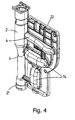
- the housing 2 of the degassing device 1 is here in a particular one-piece running side wall 22 of the Housing 11 installed, wherein the degassing device 1 is provided at an angle of the side wall (see FIG. 4).
- the inner wall structure of the side wall 22 is in the two cross sections of the figures 5a and b to see, in which two mutually connectable side wall parts 22a, 22b are shown.
- nearby a vertically erected Flow partition 24a now at the same time with an im Cross-section of continuous, inwardly extending Boundary edge 24b is provided. This can be more advantageous Way during the production of the housing 11th be poured and also serves the gases above to rest in the chamber and without Liquid to escape through the degasser 8.
- more than two Inlets with associated, substantially tangential aligned inflow can be provided and can the inflows at other positions in relation to each other be provided.
- the feeds and / or the Inflow parts of it if possible different be positioned, for example, if possible also be aligned at an angle to each other.
- the Degassing device there as a separate part be attached thereto, or the degassing device can be at a different position in a pipe system be used.
- the inlets and inlet channels can in one piece with each other or with each other be provided connectable mouthpieces. Instead of a Brenners can also use another heating element application Find.
- an effective working and compact and inexpensive to build Degassing device provided, both at non-flowing heating media as well as large Flow rates well degassed, thereby reducing the the latter then increases a centrifugal effect.
- Pressure drop is low and even lower than if two or more horizontal feed channels of a Heat exchanger should come together and with a normal 90 degree bend in a common vertical Process should go over.
Landscapes
- Engineering & Computer Science (AREA)
- Physics & Mathematics (AREA)
- Thermal Sciences (AREA)
- Chemical & Material Sciences (AREA)
- Combustion & Propulsion (AREA)
- Mechanical Engineering (AREA)
- General Engineering & Computer Science (AREA)
- Degasification And Air Bubble Elimination (AREA)
- Steam Or Hot-Water Central Heating Systems (AREA)
- Physical Water Treatments (AREA)
Abstract
Description
- Figur 1
- eine schematische perspektivische Darstellung einer Ausführungsform der erfindungsgemäßen Entgasungsvorrichtung zeigt;
- Figur 2
- eine schematische perspektivische Darstellung eines Komplexes aus einer Variante der Entgasungsvorrichtung mit einem Wärmetauscher zeigt;
- Figur 3
- schematisch das Leitungssystem zeigt, an dem die Entgasungsvorrichtung gemäß der Fig. 2 ohne Gehäuse angeschlossen ist;
- Figur 4
- die Seitenwand mit der darin integrierten Entgasungsvorrichtung gemäß der Fig. 2 zeigt; und
- Figuren 5a und 5b
- eine Querschnitt durch die Seitenwand gemäß der Fig. 4 aus entgegengesetzten Richtungen zeigen.
Claims (13)
- Entgasungsvorrichtung für ein Leitungssystem, in dem eine Flüssigkeit mit unterschiedlicher Temperatur transportierbar ist, insbesondere ein Leitungssystem einer Heizanlage, mit:wobei die Kammer (3) im wesentlichen vertikal ausgerichtet ist, der Zulauf (4, 5) im wesentlichen tangential in die Kammer (3) gerichtet ist und das Entgasungssperrventil (8) an der Oberseite der Kammer (3) vorgesehen ist,einem Gehäuse (2) mit einer im wesentlichen zylindrischen Kammer (3);mindestens einem Zulauf (4) und einem Ablauf (6) um die Kammer (3) an das Leitungssystem anzuschließen; undeinem Entgasungsabsperrventil (8), um Gase aus dem Gehäuse (2) abzuführen,
dadurch gekennzeichnet, daß
mindestens zwei Zuläufe (4, 5) zum Anschließen an das Leitungssystem vorgesehen sind, wobei die Zuläufe jeweils im wesentlichen tangential in der Kammer (3) ausgerichtet sind. - Entgasungsvorrichtung nach Anspruch 1, dadurch gekennzeichnet, daß die Zuläufe (4, 5) auf im wesentlichen der gleichen Höhe in die Kammer (3) münden.
- Entgasungsvorrichtung nach Anspruch 1 oder 2, dadurch gekennzeichnet, daß der eine Zulauf (4) um einen Winkel von im wesentlichen um 90 Grad verdreht entlang der Umfangswand der Kammer (3) im Bezug auf den anderen Zulauf (5) vorgesehen ist.
- Entgasungsvorrichtung, insbesondere nach einem der Ansprüche 1-3, für ein Leitungssystem, in dem eine Flüssigkeit mit unterschiedlicher Temperatur transportierbar ist, insbesondere ein Leitungssystem einer Heizanlage, mit:wobei die Kammer (3) im wesentlichen vertikal ausgerichtet ist, der Zulauf (4) im wesentlichen tangential in die Kammer (3) gerichtet ist und das Entgasungsabsperrventil (8) an der Oberseite der Kammer (3) vorgesehen ist,einem Gehäuse (2) mit einer im wesentlichen zylindrischen Kammer (3);mindestens einem Zulauf (4) und einem Ablauf (6), um die Kammer (3) an das Leitungssystem anzuschließen; undeinem Entgasungsabsperrventil (8), um Gase aus dem Gehäuse (2) abzuführen,
dadurch gekennzeichnet, daß
der Ablauf im wesentlichen axial ausgerichtet ist und in dem unteren Ende der Kammer (3) angeordnet ist. - Entgasungsvorrichtung nach Anspruch 4, dadurch gekennzeichnet, daß das untere Ende der Kammer (3) sich nach und nach zu einem kleineren Durchmesser verjüngt.
- Entgasungsvorrichtung nach Anspruch 4 oder 5, dadurch gekennzeichnet, daß der Ablauf (6) und das Entgasungsabsperrventil (8) im wesentlichen aufrecht übereinander vorgesehen sind.
- Entgasungsvorrichtung nach einem der Ansprüche 1-3, dadurch gekennzeichnet, daß der Ablauf (6) im wesentlichen tangential ausgerichtet ist und an die Umfangswand der Kammer (3) anschließt.
- Entgasungsvorrichtung nach einem der vorhergehenden Ansprüche, dadurch gekennzeichnet, daß oberhalb der Zuläufe (4, 5) ein Begrenzungsmittel (9) für den Flüssigkeitsstrom in der Kammer (3) vorgesehen ist.
- Entgasungsvorrichtung nach Anspruch 8, dadurch gekennzeichnet, daß das Begrenzungsmittel (9) ein sich nach innen in die Kammer (3) erstreckendes Wandteil ist.
- Komplex aus einer Entgasungsvorrichtung (1) nach einem der vorhergehenden Ansprüche mit einem Wärmetauscher (10), der ein Gehäuse (11) umfaßt, in dem ein Heizelement angeordnet ist, einem Teil eines Leitungssystems (12) mit Zu- und Ablaufkanälen (13, 14, 18, 19, 21), durch welches eine zu erwärmende Flüssigkeit transportierbar ist, wobei die Zu- und Ablaufkanäle (13, 14,18, 19, 21) an den jeweiligen Zu- und Abläufen (4, 5, 6)der Entgasungsvorrichtung (1) angeschlossen sind.
- Komplex nach Anspruch 10, dadurch gekennzeichnet, daß das Gehäuse (2) der Entgasungsvorrichtung (1) in eine Seitenwand (22) des Gehäuses (11) des Wärmetauschers eingebaut ist.
- Komplex nach Anspruch 10 oder 11, dadurch gekennzeichnet, daß die Zu- und Ablaufkanäle (13, 14, 18, 19, 21) zumindest teilweise in die Seitenwände (16, 17, 22) des Gehäuses (11) des Wärmetauschers (10) eingebaut sind.
- Heizanlage mit einer an ein Leitungssystem angeschlossenen Entgasungsvorrichtung nach einem der vorhergehenden Ansprüche.
Applications Claiming Priority (2)
| Application Number | Priority Date | Filing Date | Title |
|---|---|---|---|
| NL1025415A NL1025415C2 (nl) | 2004-02-05 | 2004-02-05 | Ontgassingsinrichting. |
| NL1025415 | 2004-02-05 |
Publications (2)
| Publication Number | Publication Date |
|---|---|
| EP1562001A1 true EP1562001A1 (de) | 2005-08-10 |
| EP1562001B1 EP1562001B1 (de) | 2012-03-28 |
Family
ID=34676045
Family Applications (1)
| Application Number | Title | Priority Date | Filing Date |
|---|---|---|---|
| EP05075217A Expired - Lifetime EP1562001B1 (de) | 2004-02-05 | 2005-01-27 | Heizanlage mit Entgasungsvorrichtung |
Country Status (3)
| Country | Link |
|---|---|
| EP (1) | EP1562001B1 (de) |
| AT (1) | ATE551574T1 (de) |
| NL (1) | NL1025415C2 (de) |
Cited By (4)
| Publication number | Priority date | Publication date | Assignee | Title |
|---|---|---|---|---|
| GB2520680A (en) * | 2013-11-27 | 2015-06-03 | Cran Simpson Ltd | Fluid processing device |
| EP2095027B1 (de) * | 2006-12-13 | 2018-03-07 | Tadpole Energy Limited | Fluidaufnahme und -übertragungsbehälter |
| NL2023920A (en) * | 2019-09-30 | 2019-12-10 | Flamco Bv | Removal device with flow control |
| EP4506626A1 (de) * | 2023-08-07 | 2025-02-12 | Vaillant GmbH | Entgasungsvorrichtung |
Families Citing this family (1)
| Publication number | Priority date | Publication date | Assignee | Title |
|---|---|---|---|---|
| DE102023119984A1 (de) * | 2023-07-27 | 2025-01-30 | Vaillant Gmbh | Gasleckagebewältigung |
Citations (2)
| Publication number | Priority date | Publication date | Assignee | Title |
|---|---|---|---|---|
| NL106105C (de) * | 1900-01-01 | |||
| US5829677A (en) * | 1996-08-12 | 1998-11-03 | Systecon, Inc. | Water heating and cooling system having a dual water mixing and air separator apparatus |
Family Cites Families (1)
| Publication number | Priority date | Publication date | Assignee | Title |
|---|---|---|---|---|
| NL8603021A (nl) | 1986-11-27 | 1988-06-16 | Nefit Nv | Inrichting voor het ontluchten van een in een leidingstelsel circulerende vloeistof. |
-
2004
- 2004-02-05 NL NL1025415A patent/NL1025415C2/nl not_active IP Right Cessation
-
2005
- 2005-01-27 EP EP05075217A patent/EP1562001B1/de not_active Expired - Lifetime
- 2005-01-27 AT AT05075217T patent/ATE551574T1/de active
Patent Citations (2)
| Publication number | Priority date | Publication date | Assignee | Title |
|---|---|---|---|---|
| NL106105C (de) * | 1900-01-01 | |||
| US5829677A (en) * | 1996-08-12 | 1998-11-03 | Systecon, Inc. | Water heating and cooling system having a dual water mixing and air separator apparatus |
Cited By (5)
| Publication number | Priority date | Publication date | Assignee | Title |
|---|---|---|---|---|
| EP2095027B1 (de) * | 2006-12-13 | 2018-03-07 | Tadpole Energy Limited | Fluidaufnahme und -übertragungsbehälter |
| GB2520680A (en) * | 2013-11-27 | 2015-06-03 | Cran Simpson Ltd | Fluid processing device |
| GB2520680B (en) * | 2013-11-27 | 2018-07-25 | Bisset James | A central heating system device |
| NL2023920A (en) * | 2019-09-30 | 2019-12-10 | Flamco Bv | Removal device with flow control |
| EP4506626A1 (de) * | 2023-08-07 | 2025-02-12 | Vaillant GmbH | Entgasungsvorrichtung |
Also Published As
| Publication number | Publication date |
|---|---|
| EP1562001B1 (de) | 2012-03-28 |
| ATE551574T1 (de) | 2012-04-15 |
| NL1025415C2 (nl) | 2005-08-08 |
Similar Documents
| Publication | Publication Date | Title |
|---|---|---|
| DE10323068B4 (de) | Flüssigkeitstank | |
| DE3419305A1 (de) | Verfahren und vorrichtung zum vermindern des gasgehaltes einer fluessigkeit | |
| DE1528657C3 (de) | Gasabscheider für Motor-Tauchpumpen | |
| EP2140920B1 (de) | Drallelement, Einlaufventil, Vorrichtung und Verfahren zum Entgasen von Flüssigkeiten | |
| EP0250734B1 (de) | Kühleinrichtung in einem flüssigkeitsgekühlten Kraftfahrzeug-Verbrennungsmotor | |
| DE19747919A1 (de) | Ventilvorrichtung | |
| EP0550510B1 (de) | Belüftungsdüse zum belüften von organische substanzen enthaltenden flüssigkeiten | |
| DE102015220315A1 (de) | Fermentationstank und Verfahren | |
| DE3345161A1 (de) | Wirbel-separator/eliminator zum entfernen von gas aus fluessigkeiten | |
| EP3348804B1 (de) | Schmiermittelbehälter für ein hydrauliksystem | |
| DE19822704B4 (de) | Gasabscheidende Brauchwasser-Zirkulationspumpe | |
| EP0874201B1 (de) | Baueinheit für eine Kompaktheizungsanlage | |
| DE2948674A1 (de) | Vorrichtung und verfahren zum entgasen einer fluessigkeit | |
| EP2429677B1 (de) | Filter | |
| EP1952046B1 (de) | Doppelsitzventil | |
| EP1562001A1 (de) | Entgasungsvorrichtung | |
| EP3643396B1 (de) | Kontinuierlich arbeitende und fluidatmende fluidmischeinrichtung und verfahren zum betrieb einer solchen | |
| CH655249A5 (de) | Einrichtung zum entgasen eines fluessigkeitskreislaufes. | |
| DE807354C (de) | Wirbelabscheider, insbesondere fuer Papiermasse | |
| DE2647970A1 (de) | Gas-fluessigkeits-trennvorrichtung | |
| EP3364043B1 (de) | Pumpenaggregat mit integrierter entlüftung- und entleerungseinheit | |
| EP0693617A1 (de) | Querstromkühler mit Entlüftung | |
| DE102009014936A1 (de) | Abwasserrohr mit einer Frischwasserleiteinrichtung sowie Wärmeübertrager | |
| DE202004011911U1 (de) | Vorrichtung zum Kühlen und Filtern eines kreislaufgeführten Fluids sowie zugehöriges Gehäuse | |
| DE102022106285B4 (de) | Vorrichtung und Verfahren zum kontinuierlichen Gasaustausch in einem Strom eines Fluidgemischs |
Legal Events
| Date | Code | Title | Description |
|---|---|---|---|
| PUAI | Public reference made under article 153(3) epc to a published international application that has entered the european phase |
Free format text: ORIGINAL CODE: 0009012 |
|
| AK | Designated contracting states |
Kind code of ref document: A1 Designated state(s): AT BE BG CH CY CZ DE DK EE ES FI FR GB GR HU IE IS IT LI LT LU MC NL PL PT RO SE SI SK TR |
|
| AX | Request for extension of the european patent |
Extension state: AL BA HR LV MK YU |
|
| 17P | Request for examination filed |
Effective date: 20060125 |
|
| AKX | Designation fees paid |
Designated state(s): AT BE BG CH CY CZ DE DK EE ES FI FR GB GR HU IE IS IT LI LT LU MC NL PL PT RO SE SI SK TR |
|
| 17Q | First examination report despatched |
Effective date: 20100119 |
|
| GRAP | Despatch of communication of intention to grant a patent |
Free format text: ORIGINAL CODE: EPIDOSNIGR1 |
|
| RTI1 | Title (correction) |
Free format text: HEATING WITH VENTING APPARATUS |
|
| GRAS | Grant fee paid |
Free format text: ORIGINAL CODE: EPIDOSNIGR3 |
|
| GRAA | (expected) grant |
Free format text: ORIGINAL CODE: 0009210 |
|
| AK | Designated contracting states |
Kind code of ref document: B1 Designated state(s): AT BE BG CH CY CZ DE DK EE ES FI FR GB GR HU IE IS IT LI LT LU MC NL PL PT RO SE SI SK TR |
|
| REG | Reference to a national code |
Ref country code: GB Ref legal event code: FG4D Free format text: NOT ENGLISH |
|
| REG | Reference to a national code |
Ref country code: CH Ref legal event code: EP |
|
| REG | Reference to a national code |
Ref country code: AT Ref legal event code: REF Ref document number: 551574 Country of ref document: AT Kind code of ref document: T Effective date: 20120415 |
|
| REG | Reference to a national code |
Ref country code: IE Ref legal event code: FG4D Free format text: LANGUAGE OF EP DOCUMENT: GERMAN |
|
| REG | Reference to a national code |
Ref country code: DE Ref legal event code: R096 Ref document number: 502005012573 Country of ref document: DE Effective date: 20120524 |
|
| REG | Reference to a national code |
Ref country code: NL Ref legal event code: T3 |
|
| REG | Reference to a national code |
Ref country code: CH Ref legal event code: NV Representative=s name: FIAMMENGHI-FIAMMENGHI |
|
| PG25 | Lapsed in a contracting state [announced via postgrant information from national office to epo] |
Ref country code: LT Free format text: LAPSE BECAUSE OF FAILURE TO SUBMIT A TRANSLATION OF THE DESCRIPTION OR TO PAY THE FEE WITHIN THE PRESCRIBED TIME-LIMIT Effective date: 20120328 |
|
| LTIE | Lt: invalidation of european patent or patent extension |
Effective date: 20120328 |
|
| PG25 | Lapsed in a contracting state [announced via postgrant information from national office to epo] |
Ref country code: GR Free format text: LAPSE BECAUSE OF FAILURE TO SUBMIT A TRANSLATION OF THE DESCRIPTION OR TO PAY THE FEE WITHIN THE PRESCRIBED TIME-LIMIT Effective date: 20120629 Ref country code: FI Free format text: LAPSE BECAUSE OF FAILURE TO SUBMIT A TRANSLATION OF THE DESCRIPTION OR TO PAY THE FEE WITHIN THE PRESCRIBED TIME-LIMIT Effective date: 20120328 |
|
| PG25 | Lapsed in a contracting state [announced via postgrant information from national office to epo] |
Ref country code: CY Free format text: LAPSE BECAUSE OF FAILURE TO SUBMIT A TRANSLATION OF THE DESCRIPTION OR TO PAY THE FEE WITHIN THE PRESCRIBED TIME-LIMIT Effective date: 20120328 |
|
| PG25 | Lapsed in a contracting state [announced via postgrant information from national office to epo] |
Ref country code: SE Free format text: LAPSE BECAUSE OF FAILURE TO SUBMIT A TRANSLATION OF THE DESCRIPTION OR TO PAY THE FEE WITHIN THE PRESCRIBED TIME-LIMIT Effective date: 20120328 Ref country code: SI Free format text: LAPSE BECAUSE OF FAILURE TO SUBMIT A TRANSLATION OF THE DESCRIPTION OR TO PAY THE FEE WITHIN THE PRESCRIBED TIME-LIMIT Effective date: 20120328 Ref country code: IS Free format text: LAPSE BECAUSE OF FAILURE TO SUBMIT A TRANSLATION OF THE DESCRIPTION OR TO PAY THE FEE WITHIN THE PRESCRIBED TIME-LIMIT Effective date: 20120728 Ref country code: RO Free format text: LAPSE BECAUSE OF FAILURE TO SUBMIT A TRANSLATION OF THE DESCRIPTION OR TO PAY THE FEE WITHIN THE PRESCRIBED TIME-LIMIT Effective date: 20120328 Ref country code: PL Free format text: LAPSE BECAUSE OF FAILURE TO SUBMIT A TRANSLATION OF THE DESCRIPTION OR TO PAY THE FEE WITHIN THE PRESCRIBED TIME-LIMIT Effective date: 20120328 Ref country code: CZ Free format text: LAPSE BECAUSE OF FAILURE TO SUBMIT A TRANSLATION OF THE DESCRIPTION OR TO PAY THE FEE WITHIN THE PRESCRIBED TIME-LIMIT Effective date: 20120328 Ref country code: EE Free format text: LAPSE BECAUSE OF FAILURE TO SUBMIT A TRANSLATION OF THE DESCRIPTION OR TO PAY THE FEE WITHIN THE PRESCRIBED TIME-LIMIT Effective date: 20120328 |
|
| PG25 | Lapsed in a contracting state [announced via postgrant information from national office to epo] |
Ref country code: SK Free format text: LAPSE BECAUSE OF FAILURE TO SUBMIT A TRANSLATION OF THE DESCRIPTION OR TO PAY THE FEE WITHIN THE PRESCRIBED TIME-LIMIT Effective date: 20120328 Ref country code: PT Free format text: LAPSE BECAUSE OF FAILURE TO SUBMIT A TRANSLATION OF THE DESCRIPTION OR TO PAY THE FEE WITHIN THE PRESCRIBED TIME-LIMIT Effective date: 20120730 |
|
| PG25 | Lapsed in a contracting state [announced via postgrant information from national office to epo] |
Ref country code: DK Free format text: LAPSE BECAUSE OF FAILURE TO SUBMIT A TRANSLATION OF THE DESCRIPTION OR TO PAY THE FEE WITHIN THE PRESCRIBED TIME-LIMIT Effective date: 20120328 |
|
| PLBE | No opposition filed within time limit |
Free format text: ORIGINAL CODE: 0009261 |
|
| STAA | Information on the status of an ep patent application or granted ep patent |
Free format text: STATUS: NO OPPOSITION FILED WITHIN TIME LIMIT |
|
| 26N | No opposition filed |
Effective date: 20130103 |
|
| REG | Reference to a national code |
Ref country code: DE Ref legal event code: R097 Ref document number: 502005012573 Country of ref document: DE Effective date: 20130103 |
|
| PG25 | Lapsed in a contracting state [announced via postgrant information from national office to epo] |
Ref country code: ES Free format text: LAPSE BECAUSE OF FAILURE TO SUBMIT A TRANSLATION OF THE DESCRIPTION OR TO PAY THE FEE WITHIN THE PRESCRIBED TIME-LIMIT Effective date: 20120709 |
|
| PG25 | Lapsed in a contracting state [announced via postgrant information from national office to epo] |
Ref country code: BG Free format text: LAPSE BECAUSE OF FAILURE TO SUBMIT A TRANSLATION OF THE DESCRIPTION OR TO PAY THE FEE WITHIN THE PRESCRIBED TIME-LIMIT Effective date: 20120628 |
|
| PG25 | Lapsed in a contracting state [announced via postgrant information from national office to epo] |
Ref country code: MC Free format text: LAPSE BECAUSE OF NON-PAYMENT OF DUE FEES Effective date: 20130131 |
|
| REG | Reference to a national code |
Ref country code: IE Ref legal event code: MM4A |
|
| PG25 | Lapsed in a contracting state [announced via postgrant information from national office to epo] |
Ref country code: IE Free format text: LAPSE BECAUSE OF NON-PAYMENT OF DUE FEES Effective date: 20130127 |
|
| REG | Reference to a national code |
Ref country code: FR Ref legal event code: PLFP Year of fee payment: 11 |
|
| PG25 | Lapsed in a contracting state [announced via postgrant information from national office to epo] |
Ref country code: TR Free format text: LAPSE BECAUSE OF FAILURE TO SUBMIT A TRANSLATION OF THE DESCRIPTION OR TO PAY THE FEE WITHIN THE PRESCRIBED TIME-LIMIT Effective date: 20120328 |
|
| PG25 | Lapsed in a contracting state [announced via postgrant information from national office to epo] |
Ref country code: LU Free format text: LAPSE BECAUSE OF NON-PAYMENT OF DUE FEES Effective date: 20130127 Ref country code: HU Free format text: LAPSE BECAUSE OF FAILURE TO SUBMIT A TRANSLATION OF THE DESCRIPTION OR TO PAY THE FEE WITHIN THE PRESCRIBED TIME-LIMIT; INVALID AB INITIO Effective date: 20050127 |
|
| REG | Reference to a national code |
Ref country code: FR Ref legal event code: PLFP Year of fee payment: 12 |
|
| PGFP | Annual fee paid to national office [announced via postgrant information from national office to epo] |
Ref country code: CH Payment date: 20160121 Year of fee payment: 12 Ref country code: IT Payment date: 20160122 Year of fee payment: 12 |
|
| PGFP | Annual fee paid to national office [announced via postgrant information from national office to epo] |
Ref country code: BE Payment date: 20160121 Year of fee payment: 12 Ref country code: AT Payment date: 20160120 Year of fee payment: 12 |
|
| REG | Reference to a national code |
Ref country code: FR Ref legal event code: PLFP Year of fee payment: 13 |
|
| PG25 | Lapsed in a contracting state [announced via postgrant information from national office to epo] |
Ref country code: BE Free format text: LAPSE BECAUSE OF NON-PAYMENT OF DUE FEES Effective date: 20170131 |
|
| REG | Reference to a national code |
Ref country code: CH Ref legal event code: PL |
|
| REG | Reference to a national code |
Ref country code: AT Ref legal event code: MM01 Ref document number: 551574 Country of ref document: AT Kind code of ref document: T Effective date: 20170127 |
|
| PG25 | Lapsed in a contracting state [announced via postgrant information from national office to epo] |
Ref country code: LI Free format text: LAPSE BECAUSE OF NON-PAYMENT OF DUE FEES Effective date: 20170131 Ref country code: AT Free format text: LAPSE BECAUSE OF NON-PAYMENT OF DUE FEES Effective date: 20170127 Ref country code: CH Free format text: LAPSE BECAUSE OF NON-PAYMENT OF DUE FEES Effective date: 20170131 |
|
| REG | Reference to a national code |
Ref country code: FR Ref legal event code: PLFP Year of fee payment: 14 |
|
| REG | Reference to a national code |
Ref country code: BE Ref legal event code: MM Effective date: 20170131 |
|
| PG25 | Lapsed in a contracting state [announced via postgrant information from national office to epo] |
Ref country code: IT Free format text: LAPSE BECAUSE OF NON-PAYMENT OF DUE FEES Effective date: 20170127 |
|
| PGFP | Annual fee paid to national office [announced via postgrant information from national office to epo] |
Ref country code: NL Payment date: 20180124 Year of fee payment: 14 |
|
| REG | Reference to a national code |
Ref country code: DE Ref legal event code: R084 Ref document number: 502005012573 Country of ref document: DE |
|
| PGFP | Annual fee paid to national office [announced via postgrant information from national office to epo] |
Ref country code: GB Payment date: 20180125 Year of fee payment: 14 Ref country code: DE Payment date: 20180308 Year of fee payment: 14 |
|
| PGFP | Annual fee paid to national office [announced via postgrant information from national office to epo] |
Ref country code: FR Payment date: 20180124 Year of fee payment: 14 |
|
| REG | Reference to a national code |
Ref country code: DE Ref legal event code: R119 Ref document number: 502005012573 Country of ref document: DE |
|
| REG | Reference to a national code |
Ref country code: NL Ref legal event code: MM Effective date: 20190201 |
|
| GBPC | Gb: european patent ceased through non-payment of renewal fee |
Effective date: 20190127 |
|
| PG25 | Lapsed in a contracting state [announced via postgrant information from national office to epo] |
Ref country code: NL Free format text: LAPSE BECAUSE OF NON-PAYMENT OF DUE FEES Effective date: 20190201 Ref country code: FR Free format text: LAPSE BECAUSE OF NON-PAYMENT OF DUE FEES Effective date: 20190131 Ref country code: DE Free format text: LAPSE BECAUSE OF NON-PAYMENT OF DUE FEES Effective date: 20190801 |
|
| PG25 | Lapsed in a contracting state [announced via postgrant information from national office to epo] |
Ref country code: GB Free format text: LAPSE BECAUSE OF NON-PAYMENT OF DUE FEES Effective date: 20190127 |