EP1561928A2 - Gasturbinentriebwerk - Google Patents
Gasturbinentriebwerk Download PDFInfo
- Publication number
- EP1561928A2 EP1561928A2 EP05250184A EP05250184A EP1561928A2 EP 1561928 A2 EP1561928 A2 EP 1561928A2 EP 05250184 A EP05250184 A EP 05250184A EP 05250184 A EP05250184 A EP 05250184A EP 1561928 A2 EP1561928 A2 EP 1561928A2
- Authority
- EP
- European Patent Office
- Prior art keywords
- condensate
- compressor
- intercooler
- cooling system
- gas turbine
- Prior art date
- Legal status (The legal status is an assumption and is not a legal conclusion. Google has not performed a legal analysis and makes no representation as to the accuracy of the status listed.)
- Granted
Links
- 238000001816 cooling Methods 0.000 claims description 46
- 238000002347 injection Methods 0.000 claims description 19
- 239000007924 injection Substances 0.000 claims description 19
- 239000012530 fluid Substances 0.000 claims description 10
- 230000005465 channeling Effects 0.000 abstract description 4
- 239000002826 coolant Substances 0.000 abstract description 2
- 239000007789 gas Substances 0.000 description 41
- 239000003570 air Substances 0.000 description 23
- 239000003595 mist Substances 0.000 description 6
- XLYOFNOQVPJJNP-UHFFFAOYSA-N water Substances O XLYOFNOQVPJJNP-UHFFFAOYSA-N 0.000 description 5
- 238000010586 diagram Methods 0.000 description 4
- 238000000034 method Methods 0.000 description 4
- 239000007921 spray Substances 0.000 description 4
- 239000012080 ambient air Substances 0.000 description 2
- 239000000567 combustion gas Substances 0.000 description 2
- 238000009833 condensation Methods 0.000 description 2
- 230000005494 condensation Effects 0.000 description 2
- 230000000694 effects Effects 0.000 description 2
- 239000000446 fuel Substances 0.000 description 2
- 238000005342 ion exchange Methods 0.000 description 2
- 238000001223 reverse osmosis Methods 0.000 description 2
- 235000013619 trace mineral Nutrition 0.000 description 2
- 239000011573 trace mineral Substances 0.000 description 2
- 238000002485 combustion reaction Methods 0.000 description 1
- 230000006835 compression Effects 0.000 description 1
- 238000007906 compression Methods 0.000 description 1
- 239000000284 extract Substances 0.000 description 1
- 239000000203 mixture Substances 0.000 description 1
- 238000010248 power generation Methods 0.000 description 1
Images


Classifications
-
- A—HUMAN NECESSITIES
- A63—SPORTS; GAMES; AMUSEMENTS
- A63B—APPARATUS FOR PHYSICAL TRAINING, GYMNASTICS, SWIMMING, CLIMBING, OR FENCING; BALL GAMES; TRAINING EQUIPMENT
- A63B71/00—Games or sports accessories not covered in groups A63B1/00 - A63B69/00
- A63B71/06—Indicating or scoring devices for games or players, or for other sports activities
- A63B71/0605—Decision makers and devices using detection means facilitating arbitration
-
- F—MECHANICAL ENGINEERING; LIGHTING; HEATING; WEAPONS; BLASTING
- F01—MACHINES OR ENGINES IN GENERAL; ENGINE PLANTS IN GENERAL; STEAM ENGINES
- F01D—NON-POSITIVE DISPLACEMENT MACHINES OR ENGINES, e.g. STEAM TURBINES
- F01D25/00—Component parts, details, or accessories, not provided for in, or of interest apart from, other groups
- F01D25/32—Collecting of condensation water; Drainage ; Removing solid particles
-
- F—MECHANICAL ENGINEERING; LIGHTING; HEATING; WEAPONS; BLASTING
- F02—COMBUSTION ENGINES; HOT-GAS OR COMBUSTION-PRODUCT ENGINE PLANTS
- F02C—GAS-TURBINE PLANTS; AIR INTAKES FOR JET-PROPULSION PLANTS; CONTROLLING FUEL SUPPLY IN AIR-BREATHING JET-PROPULSION PLANTS
- F02C3/00—Gas-turbine plants characterised by the use of combustion products as the working fluid
- F02C3/20—Gas-turbine plants characterised by the use of combustion products as the working fluid using a special fuel, oxidant, or dilution fluid to generate the combustion products
- F02C3/30—Adding water, steam or other fluids for influencing combustion, e.g. to obtain cleaner exhaust gases
- F02C3/305—Increasing the power, speed, torque or efficiency of a gas turbine or the thrust of a turbojet engine by injecting or adding water, steam or other fluids
-
- F—MECHANICAL ENGINEERING; LIGHTING; HEATING; WEAPONS; BLASTING
- F02—COMBUSTION ENGINES; HOT-GAS OR COMBUSTION-PRODUCT ENGINE PLANTS
- F02C—GAS-TURBINE PLANTS; AIR INTAKES FOR JET-PROPULSION PLANTS; CONTROLLING FUEL SUPPLY IN AIR-BREATHING JET-PROPULSION PLANTS
- F02C7/00—Features, components parts, details or accessories, not provided for in, or of interest apart form groups F02C1/00 - F02C6/00; Air intakes for jet-propulsion plants
- F02C7/12—Cooling of plants
- F02C7/14—Cooling of plants of fluids in the plant, e.g. lubricant or fuel
- F02C7/141—Cooling of plants of fluids in the plant, e.g. lubricant or fuel of working fluid
- F02C7/143—Cooling of plants of fluids in the plant, e.g. lubricant or fuel of working fluid before or between the compressor stages
- F02C7/1435—Cooling of plants of fluids in the plant, e.g. lubricant or fuel of working fluid before or between the compressor stages by water injection
-
- A—HUMAN NECESSITIES
- A63—SPORTS; GAMES; AMUSEMENTS
- A63B—APPARATUS FOR PHYSICAL TRAINING, GYMNASTICS, SWIMMING, CLIMBING, OR FENCING; BALL GAMES; TRAINING EQUIPMENT
- A63B24/00—Electric or electronic controls for exercising apparatus of preceding groups; Controlling or monitoring of exercises, sportive games, training or athletic performances
- A63B24/0021—Tracking a path or terminating locations
- A63B2024/0037—Tracking a path or terminating locations on a target surface or at impact on the ground
- A63B2024/0043—Systems for locating the point of impact on a specific surface
-
- A—HUMAN NECESSITIES
- A63—SPORTS; GAMES; AMUSEMENTS
- A63B—APPARATUS FOR PHYSICAL TRAINING, GYMNASTICS, SWIMMING, CLIMBING, OR FENCING; BALL GAMES; TRAINING EQUIPMENT
- A63B2243/00—Specific ball sports not provided for in A63B2102/00 - A63B2102/38
- A63B2243/0025—Football
-
- A—HUMAN NECESSITIES
- A63—SPORTS; GAMES; AMUSEMENTS
- A63B—APPARATUS FOR PHYSICAL TRAINING, GYMNASTICS, SWIMMING, CLIMBING, OR FENCING; BALL GAMES; TRAINING EQUIPMENT
- A63B63/00—Targets or goals for ball games
-
- F—MECHANICAL ENGINEERING; LIGHTING; HEATING; WEAPONS; BLASTING
- F05—INDEXING SCHEMES RELATING TO ENGINES OR PUMPS IN VARIOUS SUBCLASSES OF CLASSES F01-F04
- F05D—INDEXING SCHEME FOR ASPECTS RELATING TO NON-POSITIVE-DISPLACEMENT MACHINES OR ENGINES, GAS-TURBINES OR JET-PROPULSION PLANTS
- F05D2260/00—Function
- F05D2260/20—Heat transfer, e.g. cooling
- F05D2260/211—Heat transfer, e.g. cooling by intercooling, e.g. during a compression cycle
-
- Y—GENERAL TAGGING OF NEW TECHNOLOGICAL DEVELOPMENTS; GENERAL TAGGING OF CROSS-SECTIONAL TECHNOLOGIES SPANNING OVER SEVERAL SECTIONS OF THE IPC; TECHNICAL SUBJECTS COVERED BY FORMER USPC CROSS-REFERENCE ART COLLECTIONS [XRACs] AND DIGESTS
- Y02—TECHNOLOGIES OR APPLICATIONS FOR MITIGATION OR ADAPTATION AGAINST CLIMATE CHANGE
- Y02T—CLIMATE CHANGE MITIGATION TECHNOLOGIES RELATED TO TRANSPORTATION
- Y02T50/00—Aeronautics or air transport
- Y02T50/60—Efficient propulsion technologies, e.g. for aircraft
Definitions
- This invention relates generally to gas turbine engines, and more specifically to methods and apparatus for operating gas turbine engines.
- Gas turbine engines generally include, in serial flow arrangement, a high-pressure compressor for compressing air flowing through the engine, a combustor in which fuel is mixed with the compressed air and ignited to form a high temperature gas stream, and a high pressure turbine.
- the high-pressure compressor, combustor and high-pressure turbine are sometimes collectively referred to as the core engine.
- Such gas turbine engines also may include a low-pressure compressor, or booster, for supplying compressed air to the high pressure compressor.
- Gas turbine engines are used in many applications, including in aircraft, power generation, and marine applications.
- the desired engine operating characteristics vary, of course, from application to application. More particularly, when the engine is operated in an environment in which the ambient temperature is reduced in comparison to other environments, the engine may be capable of operating with a higher shaft horse power (SHP) and an increased output, without increasing the core engine temperature to unacceptably high levels. However, if the ambient temperature is increased, the core engine temperature may rise to an unacceptably high level if a high SHP output is being delivered.
- SHP shaft horse power
- At least some known gas turbine engines include an intercooler heat exchanger positioned between the booster compressor and the high pressure compressor to facilitate reducing the temperature of the air entering the high pressure compressor.
- an intercooler facilitates increasing the efficiency of the engine while reducing the quantity of work performed by the high pressure compressor.
- water condenses out of the intercooler airstream into the bottom of the intercooler. Consequently, the water is removed from the engine cooling cycle which may result in both an output power and an efficiency of the gas turbine engine being reduced.
- a method for operating a gas turbine engine including a first compressor, a second compressor, a combustor and a turbine, coupled together in serial flow arrangement.
- the method includes channeling compressed airflow discharged from the first compressor through an intercooler having a cooling medium flowing therethrough, operating the intercooler such that condensate is formed in the intercooler from the compressed airflow, and channeling the condensate to an inlet of the second compressor to facilitate reducing an operating temperature of the gas turbine engine.
- a cooling system for a gas turbine engine that includes at least a first compressor, a second compressor, and a turbine.
- the cooling system includes an intercooler coupled downstream from the first compressor such that compressed air discharged from the first compressor is routed therethrough, the intercooler having a working fluid flowing therethrough, and an injection system coupled in flow communication with the intercooler, the injection system configured to channel condensate formed in the intercooler into the second compressor to facilitate reducing an operating temperature of the gas turbine engine.
- a gas turbine engine in a further aspect, includes a first compressor, a second compressor downstream from the first compressor, a turbine coupled in flow communication with the second compressor, and a cooling system.
- the cooling system includes an intercooler coupled downstream from the first compressor such that compressed air discharged from the first compressor is routed therethrough, the intercooler having a working fluid flowing therethrough, and an injection system coupled in flow communication with the intercooler, the injection system is configured to channel condensate formed in the intercooler into the second compressor to facilitate reducing an operating temperature of the gas turbine engine.
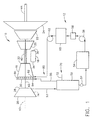
- FIG. 1 is a block diagram of a gas turbine engine 10 including a cooling system 12.
- gas turbine engine 10 is a dry-low emission (DLE) gas turbine engine.
- DLE dry-low emission
- engine 10 is known in the art and includes, in serial flow relationship, a low pressure compressor or booster 14, a high pressure compressor 16, a combustor 18, a high pressure turbine 20, a low pressure, or intermediate turbine 22, and a power turbine or free turbine 24.
- Low pressure compressor or booster 14 has an inlet 26 and an outlet 28, and high pressure compressor 16 includes an inlet 30 and an outlet 32.
- Combustor 18 has an inlet 34 that is substantially coincident with high pressure compressor outlet 32, and an outlet 36.
- High pressure turbine 20 is coupled to high pressure compressor 16 with a first rotor shaft 40, and low pressure turbine 22 is coupled to low pressure compressor 14 with a second rotor shaft 42.
- Rotor shafts 40 and 42 are each substantially coaxially aligned with respect to a longitudinal centerline axis 43 of engine 10.
- Engine 10 may be used to drive a load (not shown) which may be coupled to a power turbine shaft 44. Alternatively, the load may be coupled to a forward extension (not shown) of rotor shaft 42.
- ambient air drawn into low pressure compressor inlet 26 is compressed and channeled downstream to high pressure compressor 16.
- High pressure compressor 16 further compresses the air and delivers high pressure air to combustor 18 where it is mixed with fuel, and the mixture is ignited to generate high temperature combustion gases.
- the combustion gases are channeled from combustor 18 to drive turbines 20, 22, and 24.
- the power output of engine 10 is at least partially related to operating temperatures of the gas flow at various locations along the gas flow path. More specifically, in the exemplary embodiment, an operating temperature of the gas flow at high-pressure compressor outlet 32, and an operating temperature of the gas flow at combustor outlet 36 are closely monitored during the operation of engine 10. Reducing an operating temperature of the gas flow entering high pressure compressor 16 facilitates increasing the power output of engine 10.
- cooling system 12 includes an intercooler 50, including a drain 52, coupled in flow communication to low pressure compressor 14. Airflow 53 from low pressure compressor 14 is channeled to intercooler 50 for additional cooling prior to the cooled air 55 being returned to high-pressure compressor 16.
- Cooling system 12 also includes a condensate holding tank 54 coupled in flow communication to intercooler 50 through drain valve 52, a pump 56 coupled in flow communication to condensate holding tank 54, a demineralizer 58 coupled in flow communication to pump 56, a demineralizer condensate tank 60 coupled in flow communication to demineralizer 58, and a pump 62 coupled in flow communication to demineralizer condensate tank 60.
- Intercooler 50 has a working fluid 70 flowing therethrough for removing energy extracted from the gas flow path.
- working fluid 70 is air
- intercooler 50 is an air-to-air heat exchanger.
- working fluid 70 is water
- intercooler 50 is a air-to-water heat exchanger.
- Intercooler 50 extracts heat energy from the compressed air flow path 53 and channels cooled compressed air 55 to high pressure compressor 16.
- intercooler 50 includes a plurality of tubes (not shown) through which compressed air 53, i.e. airflow from low pressure compressor 14, circulates. Heat is transferred from compressed air 53 through a plurality of tube walls (not shown) to working fluid 70 supplied to intercooler 50 through an inlet 72.
- Cooling system 12 also includes a condensate injection system 80 coupled in flow communication with pump 62.
- Condensate injection system 80 includes a piping manifold 82 and a plurality of injectors 84 coupled to piping manifold 82.
- Piping manifold 82 is attached to gas turbine 10 and receives condensate from pump 62.
- piping manifold 82 is annular and extends circumferentially around high pressure compressor 16 to facilitate supplying a substantially consistent flow of condensate between pump 62 and injectors 84.
- Spray injectors 84 extend radially inward towards gas turbine centerline axis 43 and are configured to discharge condensate from spray injectors 84 in a fine mist towards high pressure compressor 16.
- condensate droplets exit injectors 84 with a mean diameter size of approximately twenty microns.
- working fluid 70 is channeled to intercooler 50 at a temperature that enables condensate to form in the air-side of intercooler 50.
- the condensate is then channeled from intercooler 50 and through drain valve 52 to holding tank 54.
- Pump 56 then channels the condensate from holding tank 54, through demineralizer 58, and into demineralizer holding tank 60.
- demineralizer 58 is at least one of a reverse osmosis apparatus and a ion-exchange apparatus that is configured to facilitate removing trace elements from the condensation.
- Pump 62 then channels the demineralized condensate through injection system 80 at a predetermined rate.
- the condensate exiting injection system 80 is atomized by injectors 84 and is discharged into high pressure compressor 16 as a fine mist.
- the mist facilitates reducing an operating temperature of the airflow within gas turbine engine 10, thus creating an intercooling effect that enables the air exiting high pressure compressor 16 to have an increased work capacity. Because a temperature of air 55 entering high pressure compressor 16 is reduced, less work is required for high pressure compressor 16.
- FIG. 2 is an exemplary graphical illustration of engine 10 shaft power generated using cooling system 50.
- Figure 3 is an exemplary graphical illustration of engine 10 thermal efficiency generated using cooling system 12.
- cooling system 12 when the ambient air temperature is less than approximately 60° Fahrenheit (F), condensate is not formed in intercooler 50, and thus cooling system 50 is not activated. However, when the ambient temperature increases above approximately 60° F and a desired humidity level is reached, cooling system 12 may be activated, resulting in an increased power output. For example, and more specifically, when the ambient temperature is approximately 100° F, cooling system 12 facilitates increasing the power output approximately seven megawatt (MW), i.e. approximately 8%. Moreover, and referring to Figure 3, operating cooling system 12 results in a thermal efficiency increase when the ambient temperature is approximately 100° F.
- MW megawatt
- FIG 4 is a block diagram of a gas turbine engine 10 which includes a cooling system 100.
- Cooling system 100 is substantially similar to cooling system 12, (shown in Figure 1) and components of cooling system 12 that are identical to components of cooling system 100 are identified in Figure 4 using the same reference numerals used in Figure 1.
- Cooling system 100 includes a condensate injection system 80 coupled in flow communication with pump 62.
- Condensate injection system 80 includes a piping manifold 82 and a plurality of injectors 84 coupled to piping manifold 82.
- Piping manifold 82 is attached to gas turbine 10 and receives condensate from pump 62.
- piping manifold 82 is annular and extends circumferentially around high pressure compressor 16 and to facilitate supplying a substantially consistent flow of condensate between pump 62 and injectors 84.
- Spray injectors 84 extend radially inward towards gas turbine centerline axis 43 and are configured to discharge condensate from spray injectors 84 in a fine mist towards low pressure compressor 14.
- condensate droplets exit injectors 84 with a mean diameter size of approximately twenty microns.
- working fluid 70 is channeled to intercooler 50 at a temperature that enables condensate to form in the air-side of intercooler 50.
- the condensate is then channeled from intercooler 50 and through drain valve 52 to holding tank 54.
- Pump 56 then channels the condensate from holding tank 54, through demineralizer 58, and into demineralizer holding tank 60.
- demineralizer 58 is at least one of a reverse osmosis apparatus and a ion-exchange apparatus that is configured to facilitate removing trace elements from the condensation.
- Pump 62 then channels the demineralized condensate through injection system 80 at a predetermined rate.
- the condensate exiting injection system 80 is atomized by injectors 84 and is discharged into low pressure compressor 14 as a fine mist.
- the mist facilitates reducing an operating temperature of the airflow within gas turbine engine 10, thus creating an intercooling effect that enables the air exiting high pressure compressor 16 to have an increased work capacity.
- cooling systems 12 and 100 facilitate reducing compression work required in high pressure compressor 16. Additionally, injecting condensate into either low pressure compressor 14 or high pressure compressor 16 facilitates increasing a mass flow in gas turbine engine 10 allowing gas turbine engine 10 to operate more efficiently while still producing an increased quantity of power compared to engines not utilizing cooling systems 12 or 100. Additionally, it should be realized that cooling systems 12 and 100 can also be utilized with a single annular combustion engine. Accordingly, cooling systems 12 and 100 thus facilitate improving both power output from turbine engine 10 and an increase in operating efficiency of engine 10 while utilizing condensate to cool either the low pressure compressor air or the high pressure compressor air.
- the above-described cooling systems provide a cost-effective and highly reliable method for gas flow cooling in a gas turbine engine.
- the cooling systems use a minimal quantity of condensate to cool the high pressure compressor inlet air to facilitate increasing the potential power output of the engine. Accordingly, a gas path cooling system is provided that facilitates reducing gas path temperatures thereby improving engine efficiency in a cost-effective manner.
Landscapes
- Engineering & Computer Science (AREA)
- Chemical & Material Sciences (AREA)
- Combustion & Propulsion (AREA)
- Mechanical Engineering (AREA)
- General Engineering & Computer Science (AREA)
- Health & Medical Sciences (AREA)
- General Health & Medical Sciences (AREA)
- Physical Education & Sports Medicine (AREA)
- Structures Of Non-Positive Displacement Pumps (AREA)
- Supercharger (AREA)
- Engine Equipment That Uses Special Cycles (AREA)
Applications Claiming Priority (2)
| Application Number | Priority Date | Filing Date | Title |
|---|---|---|---|
| US766437 | 2004-01-28 | ||
| US10/766,437 US7272933B2 (en) | 2004-01-28 | 2004-01-28 | Methods and apparatus for operating gas turbine engines |
Publications (3)
| Publication Number | Publication Date |
|---|---|
| EP1561928A2 true EP1561928A2 (de) | 2005-08-10 |
| EP1561928A3 EP1561928A3 (de) | 2006-09-27 |
| EP1561928B1 EP1561928B1 (de) | 2011-04-20 |
Family
ID=34679331
Family Applications (1)
| Application Number | Title | Priority Date | Filing Date |
|---|---|---|---|
| EP05250184A Expired - Fee Related EP1561928B1 (de) | 2004-01-28 | 2005-01-14 | Betriebsverfahren für ein Gasturbinenkraftwerk und zugehöriges Gasturbinenkraftwerk |
Country Status (5)
| Country | Link |
|---|---|
| US (2) | US7272933B2 (de) |
| EP (1) | EP1561928B1 (de) |
| JP (1) | JP4562129B2 (de) |
| CA (1) | CA2493500C (de) |
| DE (1) | DE602005027512D1 (de) |
Cited By (3)
| Publication number | Priority date | Publication date | Assignee | Title |
|---|---|---|---|---|
| EP2659108A4 (de) * | 2010-12-28 | 2015-06-03 | Rolls Royce Corp | Flüssigkeitseinspritzung für motor |
| EP2896806A1 (de) * | 2014-01-20 | 2015-07-22 | Siemens Aktiengesellschaft | Verändern einer Nutzleistung einer Gasturbinenanlage |
| WO2019053525A1 (en) * | 2017-09-15 | 2019-03-21 | Sabic Global Technologies B.V. | PROCESS FOR USING PURGE OF INTERMEDIATE COOLERS OF MULTI-STAGE COMPRESSORS AS A COOLING AGENT FOR AIR TREATMENT |
Families Citing this family (19)
| Publication number | Priority date | Publication date | Assignee | Title |
|---|---|---|---|---|
| US7272933B2 (en) * | 2004-01-28 | 2007-09-25 | General Electric Company | Methods and apparatus for operating gas turbine engines |
| DE102007001487B4 (de) * | 2007-01-10 | 2015-07-16 | Caterpillar Energy Solutions Gmbh | Verfahren und Vorrichtung zur Verdichterradkühlung eines Verdichters |
| JP2008175149A (ja) * | 2007-01-19 | 2008-07-31 | Hitachi Ltd | 圧縮機の吸気噴霧装置 |
| AU2009292077B2 (en) * | 2008-09-09 | 2015-05-07 | Conocophillips Company | System for enhanced gas turbine performance in a liquefied natural gas facility |
| FR2946099A1 (fr) * | 2009-05-26 | 2010-12-03 | Air Liquide | Procede de compression d'air humide. |
| IL199803A (en) | 2009-07-12 | 2012-07-31 | Lv Technologies Ltd | Method and system for enhancing engine performance |
| US20110036098A1 (en) * | 2009-08-17 | 2011-02-17 | General Electric Company | Self-regulating cooling water system for intercooled gas turbine engines |
| US8726628B2 (en) * | 2010-10-22 | 2014-05-20 | General Electric Company | Combined cycle power plant including a carbon dioxide collection system |
| ES2398095B1 (es) * | 2011-01-31 | 2014-01-27 | Universidad Politécnica De Valencia | Instalación para simular las condiciones de presión y temperatura del aire aspirado por un motor de combustión interna alternativo. |
| US8935923B2 (en) | 2011-10-25 | 2015-01-20 | United Technologies Corporation | Gas turbine engine with intercooling turbine section and intercooling turbine section bypass |
| US9140188B2 (en) | 2011-10-25 | 2015-09-22 | United Technologies Corporation | Gas turbine engine with intercooling turbine section |
| US9057328B2 (en) | 2011-11-01 | 2015-06-16 | United Technologies Corporation | Gas turbine engine with intercooling turbine section |
| US20140027097A1 (en) * | 2012-07-30 | 2014-01-30 | Ian Alexandre Araujo De Barros | Heat Exchanger for an Intercooler and Water Extraction Apparatus |
| JP6303700B2 (ja) * | 2014-03-28 | 2018-04-04 | 東京電力ホールディングス株式会社 | ガスタービンプラント及びガスタービンプラントの吸気冷却方法 |
| US20160237904A1 (en) * | 2015-02-13 | 2016-08-18 | General Electric Company | Systems and methods for controlling an inlet air temperature of an intercooled gas turbine engine |
| US10036325B2 (en) * | 2016-03-30 | 2018-07-31 | General Electric Company | Variable flow compressor of a gas turbine |
| US11112118B2 (en) * | 2016-06-27 | 2021-09-07 | General Electric Company | Gas turbine lower heating value methods and systems |
| US10801409B2 (en) * | 2016-08-02 | 2020-10-13 | Rolls-Royce North American Technologies, Inc. | Systems and methods for selectively augmenting power output of a gas turbine engine |
| US10704467B2 (en) * | 2017-04-27 | 2020-07-07 | General Electric Company | Intercooled turbine with thermal storage system |
Citations (8)
| Publication number | Priority date | Publication date | Assignee | Title |
|---|---|---|---|---|
| US2372846A (en) * | 1942-08-05 | 1945-04-03 | Nettel Frederick | Water distillation |
| US4522024A (en) * | 1981-09-18 | 1985-06-11 | Bbc Brown, Boveri & Company, Limited | Method for reducing the amount of nox and for raising the output of a gas turbine power station of the type utilizing an air reservoir, and a gas turbine power station, of this type, operating in accordance with this method |
| EP0524435A2 (de) * | 1991-06-21 | 1993-01-27 | Praxair Technology, Inc. | Verdichterauflader mit Verdampfungskühler |
| EP0770771A1 (de) * | 1995-10-26 | 1997-05-02 | Asea Brown Boveri Ag | Zwischengekühlter Verdichter |
| US5669217A (en) * | 1995-09-25 | 1997-09-23 | Anderson; J. Hilbert | Method and apparatus for intercooling gas turbines |
| US6397578B2 (en) * | 1998-05-20 | 2002-06-04 | Hitachi, Ltd. | Gas turbine power plant |
| US6412291B1 (en) * | 2000-09-05 | 2002-07-02 | Donald C. Erickson | Air compression improvement |
| WO2003102424A1 (de) * | 2002-06-04 | 2003-12-11 | Alstom Technology Ltd | Verfahren zum betreiben eines verdichters |
Family Cites Families (13)
| Publication number | Priority date | Publication date | Assignee | Title |
|---|---|---|---|---|
| JPS56162227A (en) * | 1980-05-15 | 1981-12-14 | Mitsui Eng & Shipbuild Co Ltd | Gas turbine utilizing cold heat of liquefied natural gas upon gasifying |
| US4949544A (en) | 1988-12-06 | 1990-08-21 | General Electric Company | Series intercooler |
| CA2093683C (en) | 1992-05-14 | 2002-10-15 | William Miller Farrell | Intercooled gas turbine engine |
| US5491971A (en) * | 1993-12-23 | 1996-02-20 | General Electric Co. | Closed circuit air cooled gas turbine combined cycle |
| SE502452C2 (sv) * | 1994-02-25 | 1995-10-23 | Rosen | Sätt att tillföra ånga till insugsluften till en förbränningsmotor och en anordning därtill |
| US6430931B1 (en) | 1997-10-22 | 2002-08-13 | General Electric Company | Gas turbine in-line intercooler |
| US6467252B1 (en) * | 1998-07-24 | 2002-10-22 | General Electric Company | Nozzles for water injection in a turbine engine |
| US6196165B1 (en) * | 1998-11-12 | 2001-03-06 | Munters Euroform Gmbh | Device for supplying vapor to the intake air of an internal combustion engine |
| US6578362B1 (en) * | 1999-05-17 | 2003-06-17 | General Electric Co. | Methods and apparatus for supplying cooling air to turbine engines |
| DE19938292A1 (de) * | 1999-08-12 | 2001-02-15 | Munters Euroform Gmbh Carl | Vorrichtung zur Befeuchtung der Einlaßluft von Brennkraftmaschinen mit Turbolader |
| DE19938356A1 (de) * | 1999-08-13 | 2001-02-15 | Munters Euroform Gmbh Carl | Befeuchtungsvorrichtung für die Einlaßluft von Brennkraftmaschinen |
| US6584778B1 (en) * | 2000-05-11 | 2003-07-01 | General Electric Co. | Methods and apparatus for supplying cooling air to turbine engines |
| US7272933B2 (en) * | 2004-01-28 | 2007-09-25 | General Electric Company | Methods and apparatus for operating gas turbine engines |
-
2004
- 2004-01-28 US US10/766,437 patent/US7272933B2/en active Active
-
2005
- 2005-01-14 DE DE602005027512T patent/DE602005027512D1/de active Active
- 2005-01-14 EP EP05250184A patent/EP1561928B1/de not_active Expired - Fee Related
- 2005-01-20 CA CA2493500A patent/CA2493500C/en not_active Expired - Fee Related
- 2005-01-28 JP JP2005021071A patent/JP4562129B2/ja not_active Expired - Fee Related
-
2007
- 2007-09-10 US US11/852,802 patent/US7685827B2/en not_active Expired - Lifetime
Patent Citations (8)
| Publication number | Priority date | Publication date | Assignee | Title |
|---|---|---|---|---|
| US2372846A (en) * | 1942-08-05 | 1945-04-03 | Nettel Frederick | Water distillation |
| US4522024A (en) * | 1981-09-18 | 1985-06-11 | Bbc Brown, Boveri & Company, Limited | Method for reducing the amount of nox and for raising the output of a gas turbine power station of the type utilizing an air reservoir, and a gas turbine power station, of this type, operating in accordance with this method |
| EP0524435A2 (de) * | 1991-06-21 | 1993-01-27 | Praxair Technology, Inc. | Verdichterauflader mit Verdampfungskühler |
| US5669217A (en) * | 1995-09-25 | 1997-09-23 | Anderson; J. Hilbert | Method and apparatus for intercooling gas turbines |
| EP0770771A1 (de) * | 1995-10-26 | 1997-05-02 | Asea Brown Boveri Ag | Zwischengekühlter Verdichter |
| US6397578B2 (en) * | 1998-05-20 | 2002-06-04 | Hitachi, Ltd. | Gas turbine power plant |
| US6412291B1 (en) * | 2000-09-05 | 2002-07-02 | Donald C. Erickson | Air compression improvement |
| WO2003102424A1 (de) * | 2002-06-04 | 2003-12-11 | Alstom Technology Ltd | Verfahren zum betreiben eines verdichters |
Cited By (4)
| Publication number | Priority date | Publication date | Assignee | Title |
|---|---|---|---|---|
| EP2659108A4 (de) * | 2010-12-28 | 2015-06-03 | Rolls Royce Corp | Flüssigkeitseinspritzung für motor |
| US9546574B2 (en) | 2010-12-28 | 2017-01-17 | Rolls-Royce Corporation | Engine liquid injection |
| EP2896806A1 (de) * | 2014-01-20 | 2015-07-22 | Siemens Aktiengesellschaft | Verändern einer Nutzleistung einer Gasturbinenanlage |
| WO2019053525A1 (en) * | 2017-09-15 | 2019-03-21 | Sabic Global Technologies B.V. | PROCESS FOR USING PURGE OF INTERMEDIATE COOLERS OF MULTI-STAGE COMPRESSORS AS A COOLING AGENT FOR AIR TREATMENT |
Also Published As
| Publication number | Publication date |
|---|---|
| JP4562129B2 (ja) | 2010-10-13 |
| CA2493500C (en) | 2014-03-04 |
| US20050160736A1 (en) | 2005-07-28 |
| CA2493500A1 (en) | 2005-07-28 |
| US20080092549A1 (en) | 2008-04-24 |
| US7685827B2 (en) | 2010-03-30 |
| EP1561928B1 (de) | 2011-04-20 |
| US7272933B2 (en) | 2007-09-25 |
| EP1561928A3 (de) | 2006-09-27 |
| JP2005214208A (ja) | 2005-08-11 |
| DE602005027512D1 (de) | 2011-06-01 |
Similar Documents
| Publication | Publication Date | Title |
|---|---|---|
| EP1561928B1 (de) | Betriebsverfahren für ein Gasturbinenkraftwerk und zugehöriges Gasturbinenkraftwerk | |
| US7284377B2 (en) | Method and apparatus for operating an intercooler for a gas turbine engine | |
| EP1484489B1 (de) | Einlassluftkühlsystem für eine Gasturbine | |
| US6484508B2 (en) | Methods for operating gas turbine engines | |
| US6012279A (en) | Gas turbine engine with water injection | |
| US6389793B1 (en) | Combustion turbine cooling media supply system and related method | |
| US6553753B1 (en) | Control systems and methods for water injection in a turbine engine | |
| US6470667B1 (en) | Methods and apparatus for water injection in a turbine engine | |
| US20170184027A1 (en) | Method and system for compressor and turbine cooling | |
| US6935119B2 (en) | Methods for operating gas turbine engines | |
| US20120159923A1 (en) | System and method for using gas turbine intercooler heat in a bottoming steam cycle | |
| CN108798902B (zh) | 具有蓄热系统的中间冷却的涡轮机 | |
| US20200224590A1 (en) | Work recovery system for a gas turbine engine utilizing a recuperated supercritical co2 cycle driven by cooled cooling air waste heat | |
| US6935831B2 (en) | Methods and apparatus for operating gas turbine engines | |
| US20230374941A1 (en) | Hydrogen steam injected and inter-cooled turbine engine | |
| US6978621B2 (en) | Turbo recuperator device | |
| US6763662B2 (en) | Installation for the generation of energy |
Legal Events
| Date | Code | Title | Description |
|---|---|---|---|
| PUAI | Public reference made under article 153(3) epc to a published international application that has entered the european phase |
Free format text: ORIGINAL CODE: 0009012 |
|
| AK | Designated contracting states |
Kind code of ref document: A2 Designated state(s): AT BE BG CH CY CZ DE DK EE ES FI FR GB GR HU IE IS IT LI LT LU MC NL PL PT RO SE SI SK TR |
|
| AX | Request for extension of the european patent |
Extension state: AL BA HR LV MK YU |
|
| PUAL | Search report despatched |
Free format text: ORIGINAL CODE: 0009013 |
|
| AK | Designated contracting states |
Kind code of ref document: A3 Designated state(s): AT BE BG CH CY CZ DE DK EE ES FI FR GB GR HU IE IS IT LI LT LU MC NL PL PT RO SE SI SK TR |
|
| AX | Request for extension of the european patent |
Extension state: AL BA HR LV MK YU |
|
| RIC1 | Information provided on ipc code assigned before grant |
Ipc: F02C 7/143 20060101ALI20060823BHEP Ipc: F01D 25/32 20060101ALI20060823BHEP Ipc: F02C 3/30 20060101AFI20050401BHEP |
|
| 17P | Request for examination filed |
Effective date: 20070327 |
|
| AKX | Designation fees paid |
Designated state(s): DE FR GB |
|
| 17Q | First examination report despatched |
Effective date: 20070511 |
|
| RTI1 | Title (correction) |
Free format text: METHOD FOR OPERATING A GAS TURBINE ENGINE AND CORRESPONDING GAS TURBINE ENGINE |
|
| GRAP | Despatch of communication of intention to grant a patent |
Free format text: ORIGINAL CODE: EPIDOSNIGR1 |
|
| GRAS | Grant fee paid |
Free format text: ORIGINAL CODE: EPIDOSNIGR3 |
|
| GRAA | (expected) grant |
Free format text: ORIGINAL CODE: 0009210 |
|
| AK | Designated contracting states |
Kind code of ref document: B1 Designated state(s): DE FR GB |
|
| REG | Reference to a national code |
Ref country code: GB Ref legal event code: FG4D |
|
| REF | Corresponds to: |
Ref document number: 602005027512 Country of ref document: DE Date of ref document: 20110601 Kind code of ref document: P |
|
| REG | Reference to a national code |
Ref country code: DE Ref legal event code: R096 Ref document number: 602005027512 Country of ref document: DE Effective date: 20110601 |
|
| PLBE | No opposition filed within time limit |
Free format text: ORIGINAL CODE: 0009261 |
|
| STAA | Information on the status of an ep patent application or granted ep patent |
Free format text: STATUS: NO OPPOSITION FILED WITHIN TIME LIMIT |
|
| 26N | No opposition filed |
Effective date: 20120123 |
|
| REG | Reference to a national code |
Ref country code: DE Ref legal event code: R097 Ref document number: 602005027512 Country of ref document: DE Effective date: 20120123 |
|
| REG | Reference to a national code |
Ref country code: FR Ref legal event code: PLFP Year of fee payment: 12 |
|
| REG | Reference to a national code |
Ref country code: FR Ref legal event code: PLFP Year of fee payment: 13 |
|
| PGFP | Annual fee paid to national office [announced via postgrant information from national office to epo] |
Ref country code: FR Payment date: 20170125 Year of fee payment: 13 Ref country code: DE Payment date: 20170125 Year of fee payment: 13 |
|
| PGFP | Annual fee paid to national office [announced via postgrant information from national office to epo] |
Ref country code: GB Payment date: 20170127 Year of fee payment: 13 |
|
| REG | Reference to a national code |
Ref country code: DE Ref legal event code: R119 Ref document number: 602005027512 Country of ref document: DE |
|
| GBPC | Gb: european patent ceased through non-payment of renewal fee |
Effective date: 20180114 |
|
| PG25 | Lapsed in a contracting state [announced via postgrant information from national office to epo] |
Ref country code: DE Free format text: LAPSE BECAUSE OF NON-PAYMENT OF DUE FEES Effective date: 20180801 Ref country code: FR Free format text: LAPSE BECAUSE OF NON-PAYMENT OF DUE FEES Effective date: 20180131 |
|
| REG | Reference to a national code |
Ref country code: FR Ref legal event code: ST Effective date: 20180928 |
|
| PG25 | Lapsed in a contracting state [announced via postgrant information from national office to epo] |
Ref country code: GB Free format text: LAPSE BECAUSE OF NON-PAYMENT OF DUE FEES Effective date: 20180114 |