EP1484489B1 - Einlassluftkühlsystem für eine Gasturbine - Google Patents
Einlassluftkühlsystem für eine Gasturbine Download PDFInfo
- Publication number
- EP1484489B1 EP1484489B1 EP04253168.1A EP04253168A EP1484489B1 EP 1484489 B1 EP1484489 B1 EP 1484489B1 EP 04253168 A EP04253168 A EP 04253168A EP 1484489 B1 EP1484489 B1 EP 1484489B1
- Authority
- EP
- European Patent Office
- Prior art keywords
- gas turbine
- pressure compressor
- heat exchanger
- compressor
- turbine engine
- Prior art date
- Legal status (The legal status is an assumption and is not a legal conclusion. Google has not performed a legal analysis and makes no representation as to the accuracy of the status listed.)
- Expired - Lifetime
Links
- 238000001816 cooling Methods 0.000 title claims description 18
- 239000012530 fluid Substances 0.000 claims description 11
- XLYOFNOQVPJJNP-UHFFFAOYSA-N water Substances O XLYOFNOQVPJJNP-UHFFFAOYSA-N 0.000 claims description 6
- 238000004891 communication Methods 0.000 claims description 5
- 238000011084 recovery Methods 0.000 claims description 2
- QGZKDVFQNNGYKY-UHFFFAOYSA-N Ammonia Chemical compound N QGZKDVFQNNGYKY-UHFFFAOYSA-N 0.000 claims 2
- 229910021529 ammonia Inorganic materials 0.000 claims 1
- 239000000203 mixture Substances 0.000 claims 1
- -1 steam Substances 0.000 claims 1
- 239000007789 gas Substances 0.000 description 28
- 239000000284 extract Substances 0.000 description 3
- 239000000446 fuel Substances 0.000 description 3
- 238000000034 method Methods 0.000 description 3
- 239000000567 combustion gas Substances 0.000 description 2
- 238000010586 diagram Methods 0.000 description 2
- 238000010521 absorption reaction Methods 0.000 description 1
- 239000000112 cooling gas Substances 0.000 description 1
- 238000002347 injection Methods 0.000 description 1
- 239000007924 injection Substances 0.000 description 1
- 238000010248 power generation Methods 0.000 description 1
- 238000005057 refrigeration Methods 0.000 description 1
- 239000007921 spray Substances 0.000 description 1
Images
Classifications
-
- F—MECHANICAL ENGINEERING; LIGHTING; HEATING; WEAPONS; BLASTING
- F02—COMBUSTION ENGINES; HOT-GAS OR COMBUSTION-PRODUCT ENGINE PLANTS
- F02C—GAS-TURBINE PLANTS; AIR INTAKES FOR JET-PROPULSION PLANTS; CONTROLLING FUEL SUPPLY IN AIR-BREATHING JET-PROPULSION PLANTS
- F02C7/00—Features, components parts, details or accessories, not provided for in, or of interest apart form groups F02C1/00 - F02C6/00; Air intakes for jet-propulsion plants
- F02C7/12—Cooling of plants
- F02C7/14—Cooling of plants of fluids in the plant, e.g. lubricant or fuel
- F02C7/141—Cooling of plants of fluids in the plant, e.g. lubricant or fuel of working fluid
- F02C7/143—Cooling of plants of fluids in the plant, e.g. lubricant or fuel of working fluid before or between the compressor stages
- F02C7/1435—Cooling of plants of fluids in the plant, e.g. lubricant or fuel of working fluid before or between the compressor stages by water injection
-
- F—MECHANICAL ENGINEERING; LIGHTING; HEATING; WEAPONS; BLASTING
- F01—MACHINES OR ENGINES IN GENERAL; ENGINE PLANTS IN GENERAL; STEAM ENGINES
- F01D—NON-POSITIVE DISPLACEMENT MACHINES OR ENGINES, e.g. STEAM TURBINES
- F01D15/00—Adaptations of machines or engines for special use; Combinations of engines with devices driven thereby
- F01D15/005—Adaptations for refrigeration plants
-
- F—MECHANICAL ENGINEERING; LIGHTING; HEATING; WEAPONS; BLASTING
- F02—COMBUSTION ENGINES; HOT-GAS OR COMBUSTION-PRODUCT ENGINE PLANTS
- F02C—GAS-TURBINE PLANTS; AIR INTAKES FOR JET-PROPULSION PLANTS; CONTROLLING FUEL SUPPLY IN AIR-BREATHING JET-PROPULSION PLANTS
- F02C7/00—Features, components parts, details or accessories, not provided for in, or of interest apart form groups F02C1/00 - F02C6/00; Air intakes for jet-propulsion plants
- F02C7/12—Cooling of plants
- F02C7/14—Cooling of plants of fluids in the plant, e.g. lubricant or fuel
- F02C7/141—Cooling of plants of fluids in the plant, e.g. lubricant or fuel of working fluid
- F02C7/143—Cooling of plants of fluids in the plant, e.g. lubricant or fuel of working fluid before or between the compressor stages
-
- F—MECHANICAL ENGINEERING; LIGHTING; HEATING; WEAPONS; BLASTING
- F04—POSITIVE - DISPLACEMENT MACHINES FOR LIQUIDS; PUMPS FOR LIQUIDS OR ELASTIC FLUIDS
- F04D—NON-POSITIVE-DISPLACEMENT PUMPS
- F04D29/00—Details, component parts, or accessories
- F04D29/58—Cooling; Heating; Diminishing heat transfer
- F04D29/582—Cooling; Heating; Diminishing heat transfer specially adapted for elastic fluid pumps
- F04D29/5826—Cooling at least part of the working fluid in a heat exchanger
-
- F—MECHANICAL ENGINEERING; LIGHTING; HEATING; WEAPONS; BLASTING
- F05—INDEXING SCHEMES RELATING TO ENGINES OR PUMPS IN VARIOUS SUBCLASSES OF CLASSES F01-F04
- F05D—INDEXING SCHEME FOR ASPECTS RELATING TO NON-POSITIVE-DISPLACEMENT MACHINES OR ENGINES, GAS-TURBINES OR JET-PROPULSION PLANTS
- F05D2260/00—Function
- F05D2260/20—Heat transfer, e.g. cooling
- F05D2260/205—Cooling fluid recirculation, i.e. after cooling one or more components is the cooling fluid recovered and used elsewhere for other purposes
-
- F—MECHANICAL ENGINEERING; LIGHTING; HEATING; WEAPONS; BLASTING
- F05—INDEXING SCHEMES RELATING TO ENGINES OR PUMPS IN VARIOUS SUBCLASSES OF CLASSES F01-F04
- F05D—INDEXING SCHEME FOR ASPECTS RELATING TO NON-POSITIVE-DISPLACEMENT MACHINES OR ENGINES, GAS-TURBINES OR JET-PROPULSION PLANTS
- F05D2260/00—Function
- F05D2260/20—Heat transfer, e.g. cooling
- F05D2260/211—Heat transfer, e.g. cooling by intercooling, e.g. during a compression cycle
-
- F—MECHANICAL ENGINEERING; LIGHTING; HEATING; WEAPONS; BLASTING
- F05—INDEXING SCHEMES RELATING TO ENGINES OR PUMPS IN VARIOUS SUBCLASSES OF CLASSES F01-F04
- F05D—INDEXING SCHEME FOR ASPECTS RELATING TO NON-POSITIVE-DISPLACEMENT MACHINES OR ENGINES, GAS-TURBINES OR JET-PROPULSION PLANTS
- F05D2260/00—Function
- F05D2260/20—Heat transfer, e.g. cooling
- F05D2260/212—Heat transfer, e.g. cooling by water injection
-
- F—MECHANICAL ENGINEERING; LIGHTING; HEATING; WEAPONS; BLASTING
- F05—INDEXING SCHEMES RELATING TO ENGINES OR PUMPS IN VARIOUS SUBCLASSES OF CLASSES F01-F04
- F05D—INDEXING SCHEME FOR ASPECTS RELATING TO NON-POSITIVE-DISPLACEMENT MACHINES OR ENGINES, GAS-TURBINES OR JET-PROPULSION PLANTS
- F05D2270/00—Control
- F05D2270/01—Purpose of the control system
- F05D2270/05—Purpose of the control system to affect the output of the engine
- F05D2270/053—Explicitly mentioned power
-
- Y—GENERAL TAGGING OF NEW TECHNOLOGICAL DEVELOPMENTS; GENERAL TAGGING OF CROSS-SECTIONAL TECHNOLOGIES SPANNING OVER SEVERAL SECTIONS OF THE IPC; TECHNICAL SUBJECTS COVERED BY FORMER USPC CROSS-REFERENCE ART COLLECTIONS [XRACs] AND DIGESTS
- Y02—TECHNOLOGIES OR APPLICATIONS FOR MITIGATION OR ADAPTATION AGAINST CLIMATE CHANGE
- Y02T—CLIMATE CHANGE MITIGATION TECHNOLOGIES RELATED TO TRANSPORTATION
- Y02T50/00—Aeronautics or air transport
- Y02T50/60—Efficient propulsion technologies, e.g. for aircraft
Definitions
- This invention relates generally to gas turbine engines, and more specifically to an apparatus for operating gas turbine engines.
- Gas turbine engines generally include, in serial flow arrangement, a high-pressure compressor for compressing air flowing through the engine, a combustor in which fuel is mixed with the compressed air and ignited to form a high temperature gas stream, and a high pressure turbine.
- the high-pressure compressor, combustor and high-pressure turbine are sometimes collectively referred to as the core engine.
- Such gas turbine engines also may include a low-pressure compressor, or booster, for supplying compressed air to the high pressure compressor.
- Gas turbine engines are used in many applications, including in aircraft, power generation, and marine applications.
- the desired engine operating characteristics vary, of course, from application to application. More particularly, when the engine is operated in an environment in which the ambient temperature is reduced in comparison to other environments, the engine may be capable of operating with a higher shaft horse power (SHP) and an increased output, without increasing the core engine temperature to unacceptably high levels. However, if the ambient temperature is increased, the core engine temperature may rise to an unacceptably high level if a high SHP output is being delivered.
- SHP shaft horse power
- At least some known gas turbine engines include inlet system evaporative coolers or refrigeration systems to facilitate reducing the inlet air temperature.
- solar power is used to power inlet chilling.
- Other systems use water spray fogging or injection devices to inject water into either the booster or the compressor to facilitate reducing the operating temperature of the engine.
- heat energy removed from the working fluid or gas path air, while cooling the gas path air is eventually lost to the atmosphere rather than used to further improve the efficiency of the turbine.
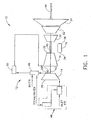
- FIG. 1 is a block diagram of a gas turbine engine 10 which includes a system for cooling gas path air generally represented at 12.
- engine 10 is known in the art and includes, in serial flow relationship, a low pressure compressor or booster 14, a high pressure compressor 16, a combustor 18, a high pressure turbine 20, a low pressure, or intermediate, turbine 22, and a power turbine or free turbine 24.
- Low pressure compressor or booster 14 has an inlet 26 and an outlet 28.
- High pressure compressor 16 includes an inlet 30 and an outlet 32.
- Combustor 18 has an inlet 34 that is substantially coincident with high pressure compressor outlet 32, and an outlet 36.
- High pressure turbine 20 is coupled to high pressure compressor 16 with a first rotor shaft 40, and low pressure turbine 22 is coupled to low pressure compressor 14 with a second rotor shaft 42.
- Rotor shaft 42 is coaxially positioned within first rotor shaft 40 about a longitudinal centerline axis of engine 10.
- Engine 10 may be used to drive a load (not shown) which may be located aft of engine 10 and is also drivingly coupled to a power turbine shaft 44.
- the load may be disposed forward of engine 10 and coupled to a forward extension (not shown) of second rotor shaft 42.
- outside air is drawn into inlet 26 of low pressure compressor 14, and compressed air is supplied from low pressure compressor 14 to high pressure compressor 16.
- High pressure compressor 16 further compresses the air and delivers the high pressure air to combustor 18 where it is mixed with fuel and the fuel ignited to generate high temperature combustion gases.
- the combustion gases are channeled from combustor 18 to drive turbines 20, 22, and 24.
- the power output of engine 10 is related to the temperatures of the gas flow at various locations along the gas flow path. More specifically, the temperature at high-pressure compressor outlet 32 and the temperature of combustor outlet 36 are closely monitored during the operation of engine 10. Lowering the temperature of the gas flow entering the compressor generally results in increasing the power output of engine 10.
- Cooling system 12 includes a heat exchanger 46 coupled in flow communication to low pressure compressor 14, and a chiller 48 coupled in flow communication to heat exchanger 46.
- Heat exchanger 46 has a working fluid flowing therethrough for storing energy extracted from the gas flow path.
- the working fluid is at least one of, but is not limited to being steam or water. More specifically, heat exchanger 46 extracts heat energy from the gas flow path and uses the extracted energy to power chiller 48. Specifically, the working fluid is routed to chiller 48 wherein energy is extracted from the working fluid to power chiller 48. Chiller 48 facilitates cooling inlet air supplied to compressor inlet 26.
- the heat exchanger 46 is a heat recovery steam generator.
- heat exchanger 46 is a water-to-air heat exchanger.
- chiller 48 is an absorption chiller.
- Cooling system 12 also includes an intercooler 50 in flow communication with, and downstream from, heat exchanger 46. Gas flow from heat exchanger 46 is channeled to intercooler 50 for additional cooling prior to being returned to high-pressure compressor 16.
- intercooler 50 is a heat exchanger.
- compressor discharge flow is channeled from low-pressure compressor 14 to heat exchanger 46.
- Heat exchanger 46 extracts sufficient heat energy from the flow to power chiller 48, while cooling the discharge flow in the process.
- the extracted energy is stored in the working fluid which is then channeled to chiller 48 and used to power chiller 48.
- Chiller 48 reduces an operating temperature of inlet air entering low-pressure compressor 14. Chiller 48 operates in a manner that is known in the art to provide cooling to reduce the operating temperature of the gas turbine inlet air.
- cooling system 12 with steam or hot water as a working fluid, can extract sufficient energy to chill the inlet air at low-pressure compressor inlet to at least 15°C (59° F), thus facilitating an improvement in both power output from turbine engine 10 and an increase in operating efficiency of engine 10.
- the low-pressure compressor discharge air is reduced at least 38°C (100° F) by using the process described herein.
- Heat exchanger 46 is in flow communication with intercooler 50 which receives cooled discharge air from heat exchanger 46.
- the discharge air can be additionally cooled to a desired temperature using intercooler 50 before being returned to high-pressure compressor 16.
- Such a reduction in the operating temperature of the gas flow facilitates reducing the power requirements for high-pressure compressor 16 and this leaves more energy available for power turbine 24.
- the temperature at high-pressure compressor outlet 32 is reduced so that the engine 10 operates with greater temperature margins relative to temperature design limits.
- the above-described cooling system provides a cost-effective and highly reliable method for gas flow cooling in a gas turbine engine.
- the cooling system uses heat energy removed from the gas path while cooling the gas path air to facilitate increasing the potential power output of the engine. Accordingly, a gas path cooling system is provided that facilitates reducing gas path temperatures thereby improving engine efficiency and reliability in a cost-effective manner.
Landscapes
- Engineering & Computer Science (AREA)
- Chemical & Material Sciences (AREA)
- Combustion & Propulsion (AREA)
- Mechanical Engineering (AREA)
- General Engineering & Computer Science (AREA)
- Physics & Mathematics (AREA)
- Thermal Sciences (AREA)
- Engine Equipment That Uses Special Cycles (AREA)
- Structures Of Non-Positive Displacement Pumps (AREA)
Claims (5)
- Gasturbinenmaschine (10) mit einem Kühlsystem (12), wobei die Gasturbinenmaschine (10) wenigstens einen Verdichter (14) und eine Turbine (22) enthält, und das Kühlsystem (12) aufweist:einen stromabwärts von dem Verdichter (14) dergestalt angeschlossenen Wärmetauscher (46), dass verdichtete Auslassluft aus dem Verdichter (14) durch diesen hindurch geführt wird, wobei der Wärmetauscher (46) ein durch diesen zirkulierendes Arbeitsfluid besitzt, um aus der verdichteten Auslassluft Wärmeenergie an das Arbeitsfluid zu übertragen; undeinen in Strömungsverbindung mit dem Wärmetauscher (46) verbundenen Kühler (48), wobei der Kühler (48) dem Arbeitsfluid Energie entzieht, um eine Reduzierung einer Temperatur der dem Verdichter (14) zugeführten Einlassluft zu ermöglichen.
- Gasturbinenmaschine (10) nach Anspruch 1, wobei der Verdichter (14) ein Niederdruckverdichter ist, die Gasturbinenmaschine (10) ferner stromabwärts von dem Niederdruckverdichter (14) einen Hochdruckverdichter (16) aufweist, während der Wärmetauscher (46) zwischen dem Niederdruckverdichter (14) und dem Hochdruckverdichter (16) positioniert ist.
- Gasturbinenmaschine (10) nach Anspruch 1, wobei der Verdichter (14) ein Niederdruckverdichter ist, die Gasturbinenmaschine (10) ferner einen Hochdruckverdichter (16) stromabwärts von dem Niederdruckverdichter (14) aufweist, und einen Zwischenkühler (50), der stromabwärts von dem Wärmetauscher (46) angeschlossen ist, wobei der Zwischenkühler (50) dafür eingerichtet ist, aus dem Wärmetauscher (46) einen Luftstrom mit einer ersten Temperatur aufzunehmen, und den Luftstrom dem Hochdruckverdichter (16) mit einer zweiten Temperatur zuzuführen, die niedriger als die erste Temperatur ist.
- Gasturbinenmaschine (10) nach Anspruch 1, wobei das Arbeitsfluid des Wärmetauschers wenigstens eines von Wasser, Dampf und einem Gemisch aus Ammoniak und Wasser ist.
- Gasturbinenmaschine (10) nach Anspruch 1, wobei der Wärmetauscher (46) ein Wärmerückgewinnungsdampfgenerator ist.
Applications Claiming Priority (2)
| Application Number | Priority Date | Filing Date | Title |
|---|---|---|---|
| US456409 | 1989-12-26 | ||
| US10/456,409 US7007484B2 (en) | 2003-06-06 | 2003-06-06 | Methods and apparatus for operating gas turbine engines |
Publications (3)
| Publication Number | Publication Date |
|---|---|
| EP1484489A2 EP1484489A2 (de) | 2004-12-08 |
| EP1484489A3 EP1484489A3 (de) | 2007-10-10 |
| EP1484489B1 true EP1484489B1 (de) | 2013-04-17 |
Family
ID=33159585
Family Applications (1)
| Application Number | Title | Priority Date | Filing Date |
|---|---|---|---|
| EP04253168.1A Expired - Lifetime EP1484489B1 (de) | 2003-06-06 | 2004-05-28 | Einlassluftkühlsystem für eine Gasturbine |
Country Status (3)
| Country | Link |
|---|---|
| US (1) | US7007484B2 (de) |
| EP (1) | EP1484489B1 (de) |
| JP (1) | JP2004360700A (de) |
Families Citing this family (32)
| Publication number | Priority date | Publication date | Assignee | Title |
|---|---|---|---|---|
| US7254950B2 (en) * | 2005-02-11 | 2007-08-14 | General Electric Company | Methods and apparatus for operating gas turbine engines |
| US20070089423A1 (en) * | 2005-10-24 | 2007-04-26 | Norman Bruce G | Gas turbine engine system and method of operating the same |
| US8584464B2 (en) * | 2005-12-20 | 2013-11-19 | General Electric Company | Gas turbine engine assembly and method of assembling same |
| US7644573B2 (en) * | 2006-04-18 | 2010-01-12 | General Electric Company | Gas turbine inlet conditioning system and method |
| US7648564B2 (en) * | 2006-06-21 | 2010-01-19 | General Electric Company | Air bypass system for gas turbine inlet |
| US7963095B2 (en) | 2006-06-21 | 2011-06-21 | General Electric Company | Inlet air conditioning system |
| JP2008175149A (ja) * | 2007-01-19 | 2008-07-31 | Hitachi Ltd | 圧縮機の吸気噴霧装置 |
| US7716930B2 (en) * | 2007-01-29 | 2010-05-18 | General Electric Company | Integrated plant cooling system |
| DE102007015309B4 (de) | 2007-03-27 | 2023-01-05 | Ansaldo Energia Switzerland AG | Betriebsverfahren für eine Turbogruppe |
| US7762054B2 (en) | 2007-08-21 | 2010-07-27 | Donald Charles Erickson | Thermally powered turbine inlet air chiller heater |
| US8220268B2 (en) * | 2007-11-28 | 2012-07-17 | Caterpillar Inc. | Turbine engine having fuel-cooled air intercooling |
| US8806849B2 (en) * | 2008-07-30 | 2014-08-19 | The University Of Wyoming | System and method of operating a power generation system with an alternative working fluid |
| US20100024378A1 (en) * | 2008-07-30 | 2010-02-04 | John Frederick Ackermann | System and method of operating a gas turbine engine with an alternative working fluid |
| BRPI0918769B1 (pt) * | 2008-09-09 | 2021-01-05 | Conocophillips Company | sistema para melhoria de performance de turbina a gás em uma usina a gás natural |
| US20110056219A1 (en) * | 2009-09-08 | 2011-03-10 | Industrial Idea Partners, Inc. | Utilization of Exhaust of Low Pressure Condensing Steam Turbine as Heat Input to Silica Gel-Water Working Pair Adsorption Chiller |
| US8234874B2 (en) * | 2009-10-09 | 2012-08-07 | General Electric Company | Systems and methods for bypassing an inlet air treatment filter |
| US20110173947A1 (en) * | 2010-01-19 | 2011-07-21 | General Electric Company | System and method for gas turbine power augmentation |
| US8475115B2 (en) | 2010-06-02 | 2013-07-02 | General Electric Company | Pre-filtration bypass for gas turbine inlet filter house |
| US8894356B2 (en) | 2011-08-23 | 2014-11-25 | General Electric Company | Retractable gas turbine inlet coils |
| US20130048265A1 (en) | 2011-08-23 | 2013-02-28 | General Electric Company | Variable temperature chiller coils |
| US9181876B2 (en) | 2012-01-04 | 2015-11-10 | General Electric Company | Method and apparatus for operating a gas turbine engine |
| ITCO20120007A1 (it) * | 2012-02-21 | 2013-08-22 | Nuovo Pignone Srl | Dispositivo di filtraggio dell'aria in ingresso per un impianto |
| US8813503B2 (en) * | 2012-06-14 | 2014-08-26 | General Electric Company | Gas turbine control systems and methods |
| JP2016519731A (ja) | 2013-03-04 | 2016-07-07 | エコージェン パワー システムズ エル.エル.シー.Echogen Power Systems, L.L.C. | 高正味電力の超臨界二酸化炭素回路を有する熱機関システム |
| WO2016073252A1 (en) | 2014-11-03 | 2016-05-12 | Echogen Power Systems, L.L.C. | Active thrust management of a turbopump within a supercritical working fluid circuit in a heat engine system |
| US20160237904A1 (en) * | 2015-02-13 | 2016-08-18 | General Electric Company | Systems and methods for controlling an inlet air temperature of an intercooled gas turbine engine |
| US11112118B2 (en) * | 2016-06-27 | 2021-09-07 | General Electric Company | Gas turbine lower heating value methods and systems |
| WO2018217969A1 (en) * | 2017-05-26 | 2018-11-29 | Echogen Power Systems Llc | Systems and methods for controlling the pressure of a working fluid at an inlet of a pressurization device of a heat engine system |
| IT201800006394A1 (it) * | 2018-06-18 | 2019-12-18 | Sistema di spurgo per cassa cuscino | |
| US10883388B2 (en) | 2018-06-27 | 2021-01-05 | Echogen Power Systems Llc | Systems and methods for generating electricity via a pumped thermal energy storage system |
| US11435120B2 (en) | 2020-05-05 | 2022-09-06 | Echogen Power Systems (Delaware), Inc. | Split expansion heat pump cycle |
| AU2021397292A1 (en) | 2020-12-09 | 2023-07-06 | Supercritical Storage Company, Inc. | Three reservoir electric thermal energy storage system |
Family Cites Families (21)
| Publication number | Priority date | Publication date | Assignee | Title |
|---|---|---|---|---|
| US4896499A (en) * | 1978-10-26 | 1990-01-30 | Rice Ivan G | Compression intercooled gas turbine combined cycle |
| JPS58101228A (ja) * | 1981-12-10 | 1983-06-16 | Mitsubishi Gas Chem Co Inc | ガスタ−ビンサイクル |
| US5095708A (en) * | 1991-03-28 | 1992-03-17 | Kalina Alexander Ifaevich | Method and apparatus for converting thermal energy into electric power |
| US5321944A (en) * | 1992-01-08 | 1994-06-21 | Ormat, Inc. | Power augmentation of a gas turbine by inlet air chilling |
| CA2093683C (en) * | 1992-05-14 | 2002-10-15 | William Miller Farrell | Intercooled gas turbine engine |
| AU7873494A (en) * | 1993-12-10 | 1995-06-27 | Cabot Corporation | An improved liquefied natural gas fueled combined cycle power plant |
| US5724806A (en) * | 1995-09-11 | 1998-03-10 | General Electric Company | Extracted, cooled, compressed/intercooled, cooling/combustion air for a gas turbine engine |
| US5768884A (en) * | 1995-11-22 | 1998-06-23 | General Electric Company | Gas turbine engine having flat rated horsepower |
| JP3778225B2 (ja) * | 1997-02-18 | 2006-05-24 | 石川島播磨重工業株式会社 | ガスタービン発電装置 |
| US6000211A (en) * | 1997-06-18 | 1999-12-14 | York Research Corporation | Solar power enhanced combustion turbine power plant and methods |
| JPH1182063A (ja) * | 1997-09-04 | 1999-03-26 | Toshiba Corp | ガスタービンプラントおよび石炭ガス化コンバインドサイクル発電プラント |
| US6050082A (en) | 1998-01-20 | 2000-04-18 | General Electric Company | Intercooled gas turbine engine with integral air bottoming cycle |
| US6058695A (en) * | 1998-04-20 | 2000-05-09 | General Electric Co. | Gas turbine inlet air cooling method for combined cycle power plants |
| DE69913695D1 (de) * | 1998-06-22 | 2004-01-29 | Silentor Holding As Hedehusene | Wärmerückgewinnungssystem |
| US6173563B1 (en) * | 1998-07-13 | 2001-01-16 | General Electric Company | Modified bottoming cycle for cooling inlet air to a gas turbine combined cycle plant |
| US6467252B1 (en) * | 1998-07-24 | 2002-10-22 | General Electric Company | Nozzles for water injection in a turbine engine |
| US6484508B2 (en) * | 1998-07-24 | 2002-11-26 | General Electric Company | Methods for operating gas turbine engines |
| JP2000110510A (ja) * | 1998-10-05 | 2000-04-18 | Takeshi Hatanaka | 高効率ガスタービン |
| GB9906620D0 (en) * | 1999-03-23 | 1999-05-19 | Rolls Royce Plc | Power generation equipment |
| JP2000328962A (ja) * | 1999-05-19 | 2000-11-28 | Mitsubishi Heavy Ind Ltd | タービン設備 |
| US6318065B1 (en) * | 1999-08-06 | 2001-11-20 | Tom L. Pierson | System for chilling inlet air for gas turbines |
-
2003
- 2003-06-06 US US10/456,409 patent/US7007484B2/en not_active Expired - Lifetime
-
2004
- 2004-05-28 EP EP04253168.1A patent/EP1484489B1/de not_active Expired - Lifetime
- 2004-06-04 JP JP2004167146A patent/JP2004360700A/ja active Pending
Also Published As
| Publication number | Publication date |
|---|---|
| EP1484489A3 (de) | 2007-10-10 |
| EP1484489A2 (de) | 2004-12-08 |
| JP2004360700A (ja) | 2004-12-24 |
| US20040244380A1 (en) | 2004-12-09 |
| US7007484B2 (en) | 2006-03-07 |
Similar Documents
| Publication | Publication Date | Title |
|---|---|---|
| EP1484489B1 (de) | Einlassluftkühlsystem für eine Gasturbine | |
| US10995670B2 (en) | Gas turbine energy supplementing systems and heating systems, and methods of making and using the same | |
| EP1561928B1 (de) | Betriebsverfahren für ein Gasturbinenkraftwerk und zugehöriges Gasturbinenkraftwerk | |
| US11047307B2 (en) | Hybrid expander cycle with intercooling and turbo-generator | |
| US6389793B1 (en) | Combustion turbine cooling media supply system and related method | |
| CA2507977C (en) | Method and apparatus for operating an intercooler for a gas turbine engine | |
| US20200088099A1 (en) | Hybrid expander cycle with turbo-generator and cooled power electronics | |
| US6050082A (en) | Intercooled gas turbine engine with integral air bottoming cycle | |
| US7219499B2 (en) | Methods and apparatus for operating gas turbine engines | |
| CN108798902B (zh) | 具有蓄热系统的中间冷却的涡轮机 | |
| US20200224590A1 (en) | Work recovery system for a gas turbine engine utilizing a recuperated supercritical co2 cycle driven by cooled cooling air waste heat | |
| US11920526B1 (en) | Inter-cooled preheat of steam injected turbine engine | |
| EP1528239B1 (de) | Vorrichtung zum Betrieb von Gasturbinen mit Verdichterzwischenkühlern | |
| US6763662B2 (en) | Installation for the generation of energy | |
| US20240141837A1 (en) | Reverse flow hydrogen steam injected turbine engine | |
| US20240141831A1 (en) | Hydrogen steam injected turbine engine with cooled cooling air |
Legal Events
| Date | Code | Title | Description |
|---|---|---|---|
| PUAI | Public reference made under article 153(3) epc to a published international application that has entered the european phase |
Free format text: ORIGINAL CODE: 0009012 |
|
| AK | Designated contracting states |
Kind code of ref document: A2 Designated state(s): AT BE BG CH CY CZ DE DK EE ES FI FR GB GR HU IE IT LI LU MC NL PL PT RO SE SI SK TR |
|
| AX | Request for extension of the european patent |
Extension state: AL HR LT LV MK |
|
| PUAL | Search report despatched |
Free format text: ORIGINAL CODE: 0009013 |
|
| AK | Designated contracting states |
Kind code of ref document: A3 Designated state(s): AT BE BG CH CY CZ DE DK EE ES FI FR GB GR HU IE IT LI LU MC NL PL PT RO SE SI SK TR |
|
| AX | Request for extension of the european patent |
Extension state: AL HR LT LV MK |
|
| 17P | Request for examination filed |
Effective date: 20080410 |
|
| AKX | Designation fees paid |
Designated state(s): DE FR GB |
|
| 17Q | First examination report despatched |
Effective date: 20080701 |
|
| REG | Reference to a national code |
Ref country code: DE Ref legal event code: R079 Ref document number: 602004041762 Country of ref document: DE Free format text: PREVIOUS MAIN CLASS: F02C0007143000 Ipc: F01D0015000000 |
|
| RIC1 | Information provided on ipc code assigned before grant |
Ipc: F04D 29/58 20060101ALI20120703BHEP Ipc: F01D 15/00 20060101AFI20120703BHEP Ipc: F02C 7/143 20060101ALI20120703BHEP |
|
| GRAP | Despatch of communication of intention to grant a patent |
Free format text: ORIGINAL CODE: EPIDOSNIGR1 |
|
| GRAS | Grant fee paid |
Free format text: ORIGINAL CODE: EPIDOSNIGR3 |
|
| GRAA | (expected) grant |
Free format text: ORIGINAL CODE: 0009210 |
|
| AK | Designated contracting states |
Kind code of ref document: B1 Designated state(s): DE FR GB |
|
| REG | Reference to a national code |
Ref country code: GB Ref legal event code: FG4D |
|
| REG | Reference to a national code |
Ref country code: DE Ref legal event code: R096 Ref document number: 602004041762 Country of ref document: DE Effective date: 20130613 |
|
| PLBE | No opposition filed within time limit |
Free format text: ORIGINAL CODE: 0009261 |
|
| STAA | Information on the status of an ep patent application or granted ep patent |
Free format text: STATUS: NO OPPOSITION FILED WITHIN TIME LIMIT |
|
| 26N | No opposition filed |
Effective date: 20140120 |
|
| REG | Reference to a national code |
Ref country code: DE Ref legal event code: R097 Ref document number: 602004041762 Country of ref document: DE Effective date: 20140120 |
|
| REG | Reference to a national code |
Ref country code: FR Ref legal event code: PLFP Year of fee payment: 13 |
|
| REG | Reference to a national code |
Ref country code: FR Ref legal event code: PLFP Year of fee payment: 14 |
|
| PGFP | Annual fee paid to national office [announced via postgrant information from national office to epo] |
Ref country code: DE Payment date: 20170530 Year of fee payment: 14 Ref country code: GB Payment date: 20170530 Year of fee payment: 14 Ref country code: FR Payment date: 20170525 Year of fee payment: 14 |
|
| REG | Reference to a national code |
Ref country code: DE Ref legal event code: R119 Ref document number: 602004041762 Country of ref document: DE |
|
| GBPC | Gb: european patent ceased through non-payment of renewal fee |
Effective date: 20180528 |
|
| PG25 | Lapsed in a contracting state [announced via postgrant information from national office to epo] |
Ref country code: DE Free format text: LAPSE BECAUSE OF NON-PAYMENT OF DUE FEES Effective date: 20181201 Ref country code: GB Free format text: LAPSE BECAUSE OF NON-PAYMENT OF DUE FEES Effective date: 20180528 Ref country code: FR Free format text: LAPSE BECAUSE OF NON-PAYMENT OF DUE FEES Effective date: 20180531 |