EP1561920A1 - Flüssigkeitsbehälter - Google Patents
Flüssigkeitsbehälter Download PDFInfo
- Publication number
- EP1561920A1 EP1561920A1 EP05000872A EP05000872A EP1561920A1 EP 1561920 A1 EP1561920 A1 EP 1561920A1 EP 05000872 A EP05000872 A EP 05000872A EP 05000872 A EP05000872 A EP 05000872A EP 1561920 A1 EP1561920 A1 EP 1561920A1
- Authority
- EP
- European Patent Office
- Prior art keywords
- liquid container
- container according
- side walls
- bottom wall
- wall
- Prior art date
- Legal status (The legal status is an assumption and is not a legal conclusion. Google has not performed a legal analysis and makes no representation as to the accuracy of the status listed.)
- Granted
Links
Images


Classifications
-
- F—MECHANICAL ENGINEERING; LIGHTING; HEATING; WEAPONS; BLASTING
- F01—MACHINES OR ENGINES IN GENERAL; ENGINE PLANTS IN GENERAL; STEAM ENGINES
- F01N—GAS-FLOW SILENCERS OR EXHAUST APPARATUS FOR MACHINES OR ENGINES IN GENERAL; GAS-FLOW SILENCERS OR EXHAUST APPARATUS FOR INTERNAL-COMBUSTION ENGINES
- F01N3/00—Exhaust or silencing apparatus having means for purifying, rendering innocuous, or otherwise treating exhaust
- F01N3/08—Exhaust or silencing apparatus having means for purifying, rendering innocuous, or otherwise treating exhaust for rendering innocuous
- F01N3/10—Exhaust or silencing apparatus having means for purifying, rendering innocuous, or otherwise treating exhaust for rendering innocuous by thermal or catalytic conversion of noxious components of exhaust
- F01N3/18—Exhaust or silencing apparatus having means for purifying, rendering innocuous, or otherwise treating exhaust for rendering innocuous by thermal or catalytic conversion of noxious components of exhaust characterised by methods of operation; Control
- F01N3/20—Exhaust or silencing apparatus having means for purifying, rendering innocuous, or otherwise treating exhaust for rendering innocuous by thermal or catalytic conversion of noxious components of exhaust characterised by methods of operation; Control specially adapted for catalytic conversion
- F01N3/206—Adding periodically or continuously substances to exhaust gases for promoting purification, e.g. catalytic material in liquid form, NOx reducing agents
- F01N3/2066—Selective catalytic reduction [SCR]
-
- B—PERFORMING OPERATIONS; TRANSPORTING
- B01—PHYSICAL OR CHEMICAL PROCESSES OR APPARATUS IN GENERAL
- B01D—SEPARATION
- B01D53/00—Separation of gases or vapours; Recovering vapours of volatile solvents from gases; Chemical or biological purification of waste gases, e.g. engine exhaust gases, smoke, fumes, flue gases, aerosols
- B01D53/34—Chemical or biological purification of waste gases
- B01D53/92—Chemical or biological purification of waste gases of engine exhaust gases
- B01D53/94—Chemical or biological purification of waste gases of engine exhaust gases by catalytic processes
- B01D53/9404—Removing only nitrogen compounds
- B01D53/9409—Nitrogen oxides
- B01D53/9431—Processes characterised by a specific device
-
- F—MECHANICAL ENGINEERING; LIGHTING; HEATING; WEAPONS; BLASTING
- F01—MACHINES OR ENGINES IN GENERAL; ENGINE PLANTS IN GENERAL; STEAM ENGINES
- F01N—GAS-FLOW SILENCERS OR EXHAUST APPARATUS FOR MACHINES OR ENGINES IN GENERAL; GAS-FLOW SILENCERS OR EXHAUST APPARATUS FOR INTERNAL-COMBUSTION ENGINES
- F01N2610/00—Adding substances to exhaust gases
- F01N2610/02—Adding substances to exhaust gases the substance being ammonia or urea
-
- F—MECHANICAL ENGINEERING; LIGHTING; HEATING; WEAPONS; BLASTING
- F01—MACHINES OR ENGINES IN GENERAL; ENGINE PLANTS IN GENERAL; STEAM ENGINES
- F01N—GAS-FLOW SILENCERS OR EXHAUST APPARATUS FOR MACHINES OR ENGINES IN GENERAL; GAS-FLOW SILENCERS OR EXHAUST APPARATUS FOR INTERNAL-COMBUSTION ENGINES
- F01N2610/00—Adding substances to exhaust gases
- F01N2610/14—Arrangements for the supply of substances, e.g. conduits
- F01N2610/1406—Storage means for substances, e.g. tanks or reservoirs
-
- Y—GENERAL TAGGING OF NEW TECHNOLOGICAL DEVELOPMENTS; GENERAL TAGGING OF CROSS-SECTIONAL TECHNOLOGIES SPANNING OVER SEVERAL SECTIONS OF THE IPC; TECHNICAL SUBJECTS COVERED BY FORMER USPC CROSS-REFERENCE ART COLLECTIONS [XRACs] AND DIGESTS
- Y02—TECHNOLOGIES OR APPLICATIONS FOR MITIGATION OR ADAPTATION AGAINST CLIMATE CHANGE
- Y02T—CLIMATE CHANGE MITIGATION TECHNOLOGIES RELATED TO TRANSPORTATION
- Y02T10/00—Road transport of goods or passengers
- Y02T10/10—Internal combustion engine [ICE] based vehicles
- Y02T10/12—Improving ICE efficiencies
Definitions
- the invention relates to a liquid container for an aqueous urea solution after Preamble of claim 1.
- the aqueous urea solution in the container interior freeze. This creates the risk of damage to the container due to the increase in volume the frozen urea solution.
- the object of the invention is therefore to provide a liquid container of the type mentioned to provide, with which ensures a safe provision of the aqueous urea solution becomes.
- the container interior starts out from its bottom wall, a filling volume which widens upwards towards its ceiling wall for the urea solution on.
- the container walls defining the side walls can be formed flat be, wherein at least one of the two side walls to expand the filling volume sloping upwards.
- the transverse cross-section to the container longitudinal extent of the container interior is trapezoidal, depending on the installation conditions, which stationary and preferred in a commercial vehicle, such as buses, trucks and the like can be used, a side wall is vertical and the other side wall is at an angle to the vertical. If it is the installation conditions allow both side walls can be inclined and, for example, in Cross-section to form an isosceles trapezoid with the bottom wall and the ceiling wall.
- the two side walls and the bottom wall and the ceiling wall of the container formed in one piece, in particular of a tubular profile.
- To this Way is achieved in a simple manner by appropriate cutting from, for example an extruded or extruded profile different, adapted to the installation conditions Container lengths.
- an extruded or extruded profile different, adapted to the installation conditions Container lengths In particular, in commercial vehicles, such as trucks, one reaches for the additional urea container a space-saving and the installation conditions adapted Container shape, which, as will be explained in detail, even at low outdoor temperatures ensures a safe supply of urea solution.
- an expanded space is created in the container interior upwards, in which the frozen urea-water solution expand during the freezing process can. Due to the slim design of the container interior is the enclosed Volume, especially in the lower area kept relatively small.
- the in the Container interior upwardly expanding filling volume in particular by the Trapezoidal cross-sectional shape of the container interior becomes a setting or crimping prevents the forming ice layer.
- a partition wall extending in container longitudinal extent in two with each other be divided communicating chambers.
- the named partition is only in the tube profile formed so that the liquid has connection via the end caps.
- the ice is divided into two blocks is divided and these two blocks do not have the high mechanical cohesion like a single block. Furthermore one achieves that the already slim profile of the Container interior is divided once again and in the two separate Chambers existing ice bodies in the warmest area, d. H. along the center of the container, in which runs the partition, can not close.
- the two have Chambers substantially equal volumes.
- a heating line may be provided, which preferably from the cooling liquid of the cooling system of the internal combustion engine is heated.
- Further heating cables may also be provided in the side walls and / or in the ceiling wall.
- the container volume must never be filled completely, but only a filling of max. 80% to 85%. This can be z. B. with an automatic shutdown a Fuel nozzle can be achieved.
- liquid container 10 which embodiments of the invention.
- the liquid containers 10 comprise a container interior 11, which of two side walls, 15, 16, a ceiling wall 18, a bottom wall 17 and two The end-side end walls 19, 20 is enclosed.
- the container interior is in the way trained that he has an upward, d. H. towards the ceiling wall 18, expanding Has filling volume for the urea solution.
- Fig. 4 it can be seen that in cross section the container interior 11 has a trapezoidal shape, which in the region of the bottom wall 17 their has narrow area and is extended in the area of the ceiling wall 18.
- the side wall 16 is substantially perpendicular, d. H. at right angles to the bottom wall 17 and the ceiling wall 18.
- the other side wall 15 runs obliquely, so that, as already explained, the enclosed container interior 11 extended to the top.
- the side walls 15, 16 and the bottom walls 17 and the Ceiling wall 18 are flat. As can be seen from the figures, one reaches This results in a slim cross-sectional profile of the urea container, which is mainly used for space-saving installation in commercial vehicles is suitable.
- the two side walls 15, 16, the Bottom walls 17 and the ceiling wall 18 in one piece, in particular of a tubular profile be formed.
- the tube profile may be an extrusion or extrusion profile.
- the pipe profile made of plastic, in particular polyethylene (PE). That for The tube profile piece used for the liquid container 10 is preferably made of a long extruded or extruded tubular profile cut to length.
- end caps 25, 26 for example by gluing, Welding or secured by screws.
- the two end walls 19, 20 are formed, which limit the container interior 11 at the front.
- the two end caps 25, 26 may be made by injection molding and also made of plastic, in particular polyethylene.
- the two end caps 25, 26 formed mirror-like.
- each end cap 25,26 receiving devices for supply connections and measuring connections, for example for a filling device 23 and a filling level sensor 22, which includes a removal device 27 may be provided.
- a filling device 23 for example, a filling device 23 and a filling level sensor 22, which includes a removal device 27 may be provided.
- Both end caps 25,26 must each have a level sensor 22. Furthermore, it is conceivable that each end cap 25, 26 has a filling device 23, so that a unification of the end caps 25,26 is achieved.
- the container interior 11 can extend through a longitudinal direction in the container Partition 14 in two chambers 12, 13 may be divided with substantially equal volumes (Fig. 4).
- This partition 14 may also in the embodiment shown in FIGS. 1 and 2 be provided. Through the partition wall ensures that in the container interior 11 form two separate ice bodies when freezing, which in the warmest Area, d. H. in the center of the container, in which the partition wall 14 extends, do not close can.
- a heating line 21 located in the region of the bottom wall 17, a heating line 21.
- two heating pipes are provided.
- the two tubes are over a pipe deflection 24, which is provided on the end cap 26, connected to each other.
- the end cap 25 In the area of the end cap 25 is the inflow and outflow for the Heating medium.
- the heating medium may be from the cooling liquid of the cooling system of the internal combustion engine, For example, the diesel engine are formed. This is the heating cable 21 connected to the cooling system of the internal combustion engine.
- Also in the side walls 15, 16 may optionally be provided heating cables, which then preferably on the outside of the side walls 15, 16 can run.
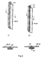
- Fig. 5 is an example of the arrangement of a level sensor 22 and a level sensor 22 shown with extraction line 27.
- the two mirror-image end caps 25,26 of the urea container 10 are preferred in the end-side end walls 19,20 vertical grooves provided in each of which an elastic sensor 22 for level measurement or a sensor 22 with a sampling line 27 knotted or glued can be.
- the removal line 27 provided in the sensor 22 in the example of FIG. 5b is because the sensor material is elastic, also elastic. By freezing the liquid in the extraction line 27, the extraction line 27 is not damaged.
- the level sensor 22 is advantageously made of an elastic, tough material, the at least on the urea solution facing side electrically semiconducting is. Both end walls 19,20 must for the level measurement such a level sensor exhibit.
- the height of the total resistance is a measure of the level indicator on the driver's seat.
Landscapes
- Chemical & Material Sciences (AREA)
- Engineering & Computer Science (AREA)
- Chemical Kinetics & Catalysis (AREA)
- Combustion & Propulsion (AREA)
- Health & Medical Sciences (AREA)
- Mechanical Engineering (AREA)
- Toxicology (AREA)
- General Engineering & Computer Science (AREA)
- Biomedical Technology (AREA)
- Environmental & Geological Engineering (AREA)
- Analytical Chemistry (AREA)
- General Chemical & Material Sciences (AREA)
- Oil, Petroleum & Natural Gas (AREA)
- Exhaust Gas After Treatment (AREA)
Abstract
Description
- 10
- Flüssigkeitsbehälter
- 11
- Behälterinnenraum
- 12,13
- Kammern
- 14
- Trennwand
- 15,16
- Seitenwände
- 17
- Bodenwand
- 18
- Deckenwand
- 19,20
- stirnseitige Endwände
- 21
- Heizleitung
- 22
- Füllstandssensor
- 23
- Füll- und Entnahmeeinrichtung
- 24
- Rohrumlenkung
- 25,26
- Endkappen
- 27
- Entnahmeleitung
Claims (11)
- Flüssigkeitsbehälter für eine wässrige Harnstofflösung, dessen Behälterinnenraum von zwei Seitenwänden, einer Deckenwand, einer Bodenwand und zwei stirnseitigen Endwänden zur Aufnahme der Harnstofflösung begrenzt wird, dadurch gekennzeichnet, dass der Behälterinnenraum (11) ausgehend von der Bodenwand (11) ein nach oben zur Deckenwand hin (18) sich erweiterndes Füllvolumen für die Harnstofflösung aufweist.
- Flüssigkeitsbehälter nach Anspruch 1, dadurch gekennzeichnet, dass die den Behälterinnenraum (11) begrenzenden Seitenwände (15,16) eben ausgebildet sind und wenigstens eine der beiden Seitenwände (15,16) schräg verläuft.
- Flüssigkeitsbehälter nach Anspruch 1 oder 2, dadurch gekennzeichnet, dass der quer zur Längsrichtung liegende Querschnitt des Behälterinnenraums (11) trapezförmig ausgebildet ist.
- Flüssigkeitsbehälter nach einem der Ansprüche 1 bis 3, dadurch gekennzeichnet, dass die beiden Seitenwände (15,16), die Bodenwand (17) und die Deckenwand (18) aus einem Stück, insbesondere aus einem Rohrprofil gebildet sind.
- Flüssigkeitsbehälter nach Anspruch 4, dadurch gekennzeichnet, dass das Rohrprofil ein Strangpress- oder Extrusionsprofil ist.
- Flüssigkeitsbehälter nach einem der Ansprüche 1 bis 5, dadurch gekennzeichnet, dass das Rohrprofil durch eine in Behälterlängsrichtung verlaufende Trennwand (14) in zwei kommunizierende Kammern (12,13) geteilt sein kann.
- Flüssigkeitsbehälter nach einem der Ansprüche 1 bis 6, dadurch gekennzeichnet, dass die beiden Endwände (19,20) an Endkappen (25,26) gebildet sind.
- Flüssigkeitsbehälter nach einem der Ansprüche 1 bis 7, dadurch gekennzeichnet, dass wenigstens eine der beiden Endwände (19,20) schräg angeordnet ist.
- Flüssigkeitsbehälter nach Anspruch 7 oder 8, dadurch gekennzeichnet, dass die Endkappen (25,26) spiegelgleich ausgebildet sind.
- Flüssigkeitsbehälter nach einem der Ansprüche 7 bis 8, dadurch gekennzeichnet, dass die Endkappen (25,26) berührende Messanschlüsse (22) und Versorgungsanschlüsse (22,23,27) aufweisen.
- Flüssigkeitsbehälter nach einem der Ansprüche 1 bis 10, dadurch gekennzeichnet, dass in oder an der Bodenwand (17) eine Heizleitung (21) vorgesehen ist.
Applications Claiming Priority (2)
| Application Number | Priority Date | Filing Date | Title |
|---|---|---|---|
| DE102004005819A DE102004005819A1 (de) | 2004-02-06 | 2004-02-06 | Flüssigkeitsbehälter |
| DE102004005819 | 2004-02-06 |
Publications (2)
| Publication Number | Publication Date |
|---|---|
| EP1561920A1 true EP1561920A1 (de) | 2005-08-10 |
| EP1561920B1 EP1561920B1 (de) | 2006-08-09 |
Family
ID=34673178
Family Applications (1)
| Application Number | Title | Priority Date | Filing Date |
|---|---|---|---|
| EP05000872A Expired - Lifetime EP1561920B1 (de) | 2004-02-06 | 2005-01-18 | Flüssigkeitsbehälter |
Country Status (2)
| Country | Link |
|---|---|
| EP (1) | EP1561920B1 (de) |
| DE (2) | DE102004005819A1 (de) |
Families Citing this family (2)
| Publication number | Priority date | Publication date | Assignee | Title |
|---|---|---|---|---|
| DE102007051922A1 (de) | 2007-10-29 | 2009-04-30 | Volkswagen Ag | Reduktionsmittelbehälter, Befüllungsstutzen, Kraftfahrzeug und Verfahren zum Befüllen eines Reduktionsmittelbehälters |
| DE102011108213A1 (de) * | 2011-07-21 | 2013-01-24 | Audi Ag | Beheizbarer Reduktionsmitteltank |
Citations (3)
| Publication number | Priority date | Publication date | Assignee | Title |
|---|---|---|---|---|
| DE19723114A1 (de) * | 1997-06-03 | 1998-12-10 | Schaefer Werke Gmbh | Behälter, insbesondere Edelstahl- oder Kunststoffaß |
| EP1199449A2 (de) * | 2000-10-20 | 2002-04-24 | MESSER GRIESHEIM GmbH | Verwendung von flüssigem Ammoniak in Abgaskatalysatorsystemen von Verbrennungsmotoren |
| US20020081239A1 (en) * | 2000-10-19 | 2002-06-27 | Hydraulik-Ring Gmbh | Device for exhaust gas after treatment of diesel engines |
-
2004
- 2004-02-06 DE DE102004005819A patent/DE102004005819A1/de not_active Withdrawn
-
2005
- 2005-01-18 DE DE502005000053T patent/DE502005000053D1/de not_active Expired - Lifetime
- 2005-01-18 EP EP05000872A patent/EP1561920B1/de not_active Expired - Lifetime
Patent Citations (3)
| Publication number | Priority date | Publication date | Assignee | Title |
|---|---|---|---|---|
| DE19723114A1 (de) * | 1997-06-03 | 1998-12-10 | Schaefer Werke Gmbh | Behälter, insbesondere Edelstahl- oder Kunststoffaß |
| US20020081239A1 (en) * | 2000-10-19 | 2002-06-27 | Hydraulik-Ring Gmbh | Device for exhaust gas after treatment of diesel engines |
| EP1199449A2 (de) * | 2000-10-20 | 2002-04-24 | MESSER GRIESHEIM GmbH | Verwendung von flüssigem Ammoniak in Abgaskatalysatorsystemen von Verbrennungsmotoren |
Also Published As
| Publication number | Publication date |
|---|---|
| EP1561920B1 (de) | 2006-08-09 |
| DE102004005819A1 (de) | 2005-08-25 |
| DE502005000053D1 (de) | 2006-09-21 |
Similar Documents
| Publication | Publication Date | Title |
|---|---|---|
| EP1506898B1 (de) | Airbagvorrichtung für Kraftfahrzeuge | |
| EP2379854B1 (de) | Eisdruckkanal-element | |
| EP1717107B1 (de) | Stossstange mit Halterungen | |
| DE19747107C2 (de) | Innenverkleidung für eine Fahrzeugkarosserie | |
| DE202017101274U1 (de) | Verbindungsaggregat | |
| EP2297539B1 (de) | Plattenkühler für flüssigkeiten | |
| DE102014118760A1 (de) | Tankvorrichtung für eine wässerige Harnstofflösung sowie Verfahren zur Reduzierung eines Eisdrucks in einer Tankvorrichtung | |
| WO2005033603A2 (de) | Wärmetauschereinheit | |
| DE19739389A1 (de) | Eisspeicher-Element | |
| EP1561920B1 (de) | Flüssigkeitsbehälter | |
| DE102019102527B4 (de) | Kraftstoffverteiler für einen Verbrennungsmotor und Verfahren zur Herstellung eines rohrförmigen Einlegekörpers für einen Kraftstoffverteiler | |
| DE19857121B4 (de) | Kältespeicher, insbesondere für die Klimatisierung eines Fahrzeuginnenraumes | |
| DE102016010138A1 (de) | Befestigungsanordnung für einen Betriebsmittelbehälter zwischen den Längsträgern eines Rahmens eines Lastkraftwagens | |
| DE102018218964A1 (de) | Fahrzeugbatterie, Fahrzeug mit einer derartigen Fahrzeugbatterie sowie Verfahren zur fluiddichten Abdichtung eines Batteriegehäuses der Fahrzeugbatterie | |
| DE102010029334A1 (de) | Fluidspeichereinrichtung | |
| DE102021130442B3 (de) | Crashmanagementsystem für ein Kraftfahrzeug mit Hohlprofilelementen und mehreren stoffschlüssigen Verbindungsabschnitten, Herstellungsverfahren hierfür und Kraftfahrzeug | |
| DE1189598B (de) | Elektrische Batterie, insbesondere fuer Kraftfahrzeuge | |
| DE19851402C1 (de) | Eisspeicherelement | |
| EP2223844A1 (de) | Frontendmodul für Fahrzeuge | |
| DE10259204B4 (de) | Kraftstoffreservoir und Verfahren zur Herstellung eines Kraftstoffreservoirs | |
| DE102021116324A1 (de) | Batterieeinrichtung und Kraftfahrzeug mit einer Batterieeinrichtung | |
| WO2009097886A1 (de) | Hybridbauteil für einen kraftwagen | |
| DE102017223862B4 (de) | Halbzeug zur Herstellung einer kombinierten Heiz- und Schwappschutzvorrichtung und daraus gebildete Vorrichtung | |
| DE102009047058A1 (de) | Vorratsbehälter sowie Abgasreinigungseinrichtung | |
| DE102010039087A1 (de) | Reduktionsmittel-Vorratsbehälter |
Legal Events
| Date | Code | Title | Description |
|---|---|---|---|
| PUAI | Public reference made under article 153(3) epc to a published international application that has entered the european phase |
Free format text: ORIGINAL CODE: 0009012 |
|
| AK | Designated contracting states |
Kind code of ref document: A1 Designated state(s): AT BE BG CH CY CZ DE DK EE ES FI FR GB GR HU IE IS IT LI LT LU MC NL PL PT RO SE SI SK TR |
|
| AX | Request for extension of the european patent |
Extension state: AL BA HR LV MK YU |
|
| GRAP | Despatch of communication of intention to grant a patent |
Free format text: ORIGINAL CODE: EPIDOSNIGR1 |
|
| 17P | Request for examination filed |
Effective date: 20060209 |
|
| AKX | Designation fees paid |
Designated state(s): DE FR IT SE |
|
| GRAS | Grant fee paid |
Free format text: ORIGINAL CODE: EPIDOSNIGR3 |
|
| GRAA | (expected) grant |
Free format text: ORIGINAL CODE: 0009210 |
|
| AK | Designated contracting states |
Kind code of ref document: B1 Designated state(s): DE FR IT SE |
|
| PG25 | Lapsed in a contracting state [announced via postgrant information from national office to epo] |
Ref country code: IT Free format text: LAPSE BECAUSE OF FAILURE TO SUBMIT A TRANSLATION OF THE DESCRIPTION OR TO PAY THE FEE WITHIN THE PRESCRIBED TIME-LIMIT;WARNING: LAPSES OF ITALIAN PATENTS WITH EFFECTIVE DATE BEFORE 2007 MAY HAVE OCCURRED AT ANY TIME BEFORE 2007. THE CORRECT EFFECTIVE DATE MAY BE DIFFERENT FROM THE ONE RECORDED. Effective date: 20060809 |
|
| REF | Corresponds to: |
Ref document number: 502005000053 Country of ref document: DE Date of ref document: 20060921 Kind code of ref document: P |
|
| REG | Reference to a national code |
Ref country code: SE Ref legal event code: TRGR |
|
| ET | Fr: translation filed | ||
| PLBE | No opposition filed within time limit |
Free format text: ORIGINAL CODE: 0009261 |
|
| STAA | Information on the status of an ep patent application or granted ep patent |
Free format text: STATUS: NO OPPOSITION FILED WITHIN TIME LIMIT |
|
| 26N | No opposition filed |
Effective date: 20070510 |
|
| PGRI | Patent reinstated in contracting state [announced from national office to epo] |
Ref country code: IT Effective date: 20090301 |
|
| REG | Reference to a national code |
Ref country code: FR Ref legal event code: CD |
|
| REG | Reference to a national code |
Ref country code: DE Ref legal event code: R081 Ref document number: 502005000053 Country of ref document: DE Owner name: MAN TRUCK & BUS AG, DE Free format text: FORMER OWNER: MAN NUTZFAHRZEUGE AG, 80995 MUENCHEN, DE Effective date: 20110518 |
|
| REG | Reference to a national code |
Ref country code: FR Ref legal event code: PLFP Year of fee payment: 12 |
|
| REG | Reference to a national code |
Ref country code: FR Ref legal event code: PLFP Year of fee payment: 13 |
|
| REG | Reference to a national code |
Ref country code: FR Ref legal event code: PLFP Year of fee payment: 14 |
|
| REG | Reference to a national code |
Ref country code: DE Ref legal event code: R081 Ref document number: 502005000053 Country of ref document: DE Owner name: MAN TRUCK & BUS SE, DE Free format text: FORMER OWNER: MAN TRUCK & BUS AG, 80995 MUENCHEN, DE |
|
| PGFP | Annual fee paid to national office [announced via postgrant information from national office to epo] |
Ref country code: FR Payment date: 20230124 Year of fee payment: 19 |
|
| PGFP | Annual fee paid to national office [announced via postgrant information from national office to epo] |
Ref country code: SE Payment date: 20230124 Year of fee payment: 19 Ref country code: IT Payment date: 20230120 Year of fee payment: 19 Ref country code: DE Payment date: 20230127 Year of fee payment: 19 |
|
| REG | Reference to a national code |
Ref country code: DE Ref legal event code: R119 Ref document number: 502005000053 Country of ref document: DE |
|
| REG | Reference to a national code |
Ref country code: SE Ref legal event code: EUG |
|
| PG25 | Lapsed in a contracting state [announced via postgrant information from national office to epo] |
Ref country code: DE Free format text: LAPSE BECAUSE OF NON-PAYMENT OF DUE FEES Effective date: 20240801 |
|
| PG25 | Lapsed in a contracting state [announced via postgrant information from national office to epo] |
Ref country code: FR Free format text: LAPSE BECAUSE OF NON-PAYMENT OF DUE FEES Effective date: 20240131 |
|
| PG25 | Lapsed in a contracting state [announced via postgrant information from national office to epo] |
Ref country code: FR Free format text: LAPSE BECAUSE OF NON-PAYMENT OF DUE FEES Effective date: 20240131 Ref country code: DE Free format text: LAPSE BECAUSE OF NON-PAYMENT OF DUE FEES Effective date: 20240801 |
|
| PG25 | Lapsed in a contracting state [announced via postgrant information from national office to epo] |
Ref country code: IT Free format text: LAPSE BECAUSE OF NON-PAYMENT OF DUE FEES Effective date: 20240118 |
|
| PG25 | Lapsed in a contracting state [announced via postgrant information from national office to epo] |
Ref country code: SE Free format text: LAPSE BECAUSE OF NON-PAYMENT OF DUE FEES Effective date: 20240119 |