EP1561882B1 - Portable vibratory screed with vibration restraint - Google Patents
Portable vibratory screed with vibration restraint Download PDFInfo
- Publication number
- EP1561882B1 EP1561882B1 EP05002192A EP05002192A EP1561882B1 EP 1561882 B1 EP1561882 B1 EP 1561882B1 EP 05002192 A EP05002192 A EP 05002192A EP 05002192 A EP05002192 A EP 05002192A EP 1561882 B1 EP1561882 B1 EP 1561882B1
- Authority
- EP
- European Patent Office
- Prior art keywords
- engine
- screed
- vibratory
- machine
- restraint
- Prior art date
- Legal status (The legal status is an assumption and is not a legal conclusion. Google has not performed a legal analysis and makes no representation as to the accuracy of the status listed.)
- Expired - Lifetime
Links
- 238000000034 method Methods 0.000 claims description 12
- 230000008878 coupling Effects 0.000 claims description 9
- 238000010168 coupling process Methods 0.000 claims description 9
- 238000005859 coupling reaction Methods 0.000 claims description 9
- 230000033001 locomotion Effects 0.000 claims description 7
- 230000000452 restraining effect Effects 0.000 claims description 5
- 229910052751 metal Inorganic materials 0.000 claims description 2
- 239000002184 metal Substances 0.000 claims description 2
- 230000013011 mating Effects 0.000 claims 1
- 238000012360 testing method Methods 0.000 description 7
- 230000005540 biological transmission Effects 0.000 description 4
- XLYOFNOQVPJJNP-UHFFFAOYSA-N water Substances O XLYOFNOQVPJJNP-UHFFFAOYSA-N 0.000 description 4
- 230000008569 process Effects 0.000 description 3
- 239000007858 starting material Substances 0.000 description 3
- 230000001133 acceleration Effects 0.000 description 2
- 230000009471 action Effects 0.000 description 2
- 238000002485 combustion reaction Methods 0.000 description 2
- 238000006073 displacement reaction Methods 0.000 description 2
- 239000000446 fuel Substances 0.000 description 2
- 239000002828 fuel tank Substances 0.000 description 2
- 239000000463 material Substances 0.000 description 2
- 230000007246 mechanism Effects 0.000 description 2
- 238000012986 modification Methods 0.000 description 2
- 230000004048 modification Effects 0.000 description 2
- 230000009467 reduction Effects 0.000 description 2
- 229910000831 Steel Inorganic materials 0.000 description 1
- 230000003213 activating effect Effects 0.000 description 1
- 229910052782 aluminium Inorganic materials 0.000 description 1
- XAGFODPZIPBFFR-UHFFFAOYSA-N aluminium Chemical compound [Al] XAGFODPZIPBFFR-UHFFFAOYSA-N 0.000 description 1
- 230000000712 assembly Effects 0.000 description 1
- 238000000429 assembly Methods 0.000 description 1
- 238000005056 compaction Methods 0.000 description 1
- 230000005611 electricity Effects 0.000 description 1
- 239000006260 foam Substances 0.000 description 1
- 239000003502 gasoline Substances 0.000 description 1
- 238000009499 grossing Methods 0.000 description 1
- 239000000203 mixture Substances 0.000 description 1
- 230000010355 oscillation Effects 0.000 description 1
- 230000004044 response Effects 0.000 description 1
- 230000002441 reversible effect Effects 0.000 description 1
- 238000007789 sealing Methods 0.000 description 1
- 230000035939 shock Effects 0.000 description 1
- 239000010959 steel Substances 0.000 description 1
- 230000001502 supplementing effect Effects 0.000 description 1
Images


Classifications
-
- E—FIXED CONSTRUCTIONS
- E04—BUILDING
- E04G—SCAFFOLDING; FORMS; SHUTTERING; BUILDING IMPLEMENTS OR AIDS, OR THEIR USE; HANDLING BUILDING MATERIALS ON THE SITE; REPAIRING, BREAKING-UP OR OTHER WORK ON EXISTING BUILDINGS
- E04G21/00—Preparing, conveying, or working-up building materials or building elements in situ; Other devices or measures for constructional work
- E04G21/02—Conveying or working-up concrete or similar masses able to be heaped or cast
- E04G21/06—Solidifying concrete, e.g. by application of vacuum before hardening
- E04G21/063—Solidifying concrete, e.g. by application of vacuum before hardening making use of vibrating or jolting tools
- E04G21/066—Solidifying concrete, e.g. by application of vacuum before hardening making use of vibrating or jolting tools acting upon the surface of the concrete, whether or not provided with parts penetrating the concrete
Definitions
- the invention relates to a portable vibratory screed machine, and, more particularly, relates to a portable vibratory screed machine having a vibration restraint configured to reduce undesirable vibrational wear on and extend the life of the machine's engine.
- Numerous screed machines employ vibratory action to tamp and smooth concrete in the strike off step of a concrete finishing operation.
- Known vibratory screed machines comprise, for instance, an elongated blade extending horizontally and transversally at lower ends of a pair of handles adapted to be hand held and operated for displacing the wet screed over a concrete surface.
- a motor is provided above the blade and between the handles. The motor's output extends to the blade, where it is connected to a vibratory assembly having one or more eccentric weights configured to impart vibrations to the screed blade upon motor operation.
- a handle permits an easy and constant correction of the level of the concrete with minimum effort.
- a throttle control is provided at the handle such that the speed of the motor may be adjusted as the blade is displaced over the concrete being surfaced.
- U.S. Pat. No. 4,340,351 which describes a vibratory concrete screed used in the final finishing of concrete. This screed requires two operators.
- U.S. Pat. No. 4,641,995 describes a vibratory concrete screed, which rides on forms to screed narrow strips of concrete, such as walks. This screed is mounted on the operator via a complicated harness counter-weighted frame and is powered by electricity. As a result, the screed requires electrical power, and the screed requires manipulation of lengthy extension cords.
- These and other screeds are designed to be used only after concrete has been leveled and preliminarily tamped. None of these screeds is suitable to "wet screed" large slabs of freshly poured concrete that has not yet been leveled or tamped at all.
- wet screeding In the absence of widely accepted wet screeding machines, the industry standard for wet screeding is to perform that process manually.
- a 2-inch by 4-inch board (5.1 cm by 10.2 cm) that is 8-foot to 20-foot long (2.44 m to 6.096 m) is manipulated manually by one or two men hand working in conjunction with as many as four laborers, known as "puddlers," who push the fresh concrete in place with concrete rakes.
- the hand puddling and wet screeding process is slow, inefficient, labor intensive, and extremely fatiguing, particularly if large slabs are poured and finished over the course of an entire day or more. It is also often requires the addition of more water to the concrete mix to make it more workable.
- Proposals have been made to reduce the labor required for wet screeding by providing portable vibratory "wet screed" machines. These machines typically have an engine coupled to an drive shaft.
- the engine is generally an internal combustion engine having a housing, a fuel thank, a clutch housing, etc.
- the drive shaft is configured to drive a vibrator drive shaft of the vibratory assembly.
- the engine housing or a support therefore is secured to a housing for the vibrator drive shaft at one point by a clamp.
- the clamp location is approximately midway between a centroid of the engine and the blade. The clamp provides only limited restraint to the engine and drive shaft relative to the vibratory assembly along the x-y reference plane.
- Vibrations generated upon screed operation by the eccentric vibratory assembly therefore are transmitted to the clamp point and generate severe vibrations on the engine about all three (x, y, z) axes.
- the vibrations are known to cause failures not only in the clutch housing, but also of the handle assembly, the fuel tank, oil seals, the engine block, etc.
- Engine block failures are the most problematic because the engine is by far the most expensive component of the wet screed. The screed therefore is typically considered spent when the engine block fails. Vibratory wet screeds therefore historically have had a reputation of being unreliable, hindering their acceptance by the industry as a whole.
- a vibrating screed for surfacing concrete comprises a surfacing blade, a pair of handle assemblies mounted to said blade, a motor, a vibration causing mechanism and a transmission connected with a motor to the vibration causing mechanism.
- the motor When the motor is in operation, it causes the transmission to rotate, the transmission being adapted to impart a vibratory motion to the blade.
- Each handle assembly comprises a main elongated tubular member and a handle mounted at a proximal end thereof.
- the handle includes a first tubular element mounted around the main tubular member, a second tubular element extending sidewise from the first element and a third tubular element extending around the second element, with a grip member being mounted to the third element.
- the first element is capable of rotatable and translational displacement with respect to the main tubular member, and the third element and grip member are capable of rotational displacement relative to the second element.
- Clamps are provided for securing the first and third tubular elements in the selected positions.
- a vibrating screed which permits selective adjustment of the angle between the axis of a rotatable eccentric and the plan define by the bottom of the screed plate.
- the screed further includes a frame, motor, an eccentric driven by the motor, a screed plate and a pair of locking hinges which releasably connect the frame to the screed plate in an angular relationship there between.
- a portable vibratory screed machine is desired with reduced undesirable vibration on the motor and expended motor life associated with operation of the vibratory screed machine in the surfacing of concrete.
- the present invention provides an improved portable vibratory screed having a vibration restraint configured to reduce undesirable vibration on the engine and to extend the engine's life.
- the apparatus is ideally suited for use with wet screeds, but is usable with other vibratory screed machines as well.
- a portable vibratory screed machine includes a machine frame having a reference structure, an engine including a drive shaft and being mounted on the reference structure via a mount that surrounds the drive shaft, a vibratory assembly located remote from the engine, the vibratory assembly powered by the engine to vibrate, and a vibration restraint configured to restrain vibration of the engine.
- the vibration restraint directly couples the engine to the reference structure at a location that is spaced apart from the mount.
- the resulting portable vibratory screed machine of the present invention has several advantages over prior vibratory plate machines.
- the vibratory plate does not interfere with or hinder normal operation of the portable vibratory screed machine. Further, the vibratory plate reduces the imposition of undesirable vibrations on the engine and thereby extends the engine life.
- the present invention provides a method of extending a life of an engine having a drive shaft configured to drive a portable vibratory assembly.
- the engine is mounted on a reference structure of the portable vibratory screed machine.
- the method includes the acts of operating the engine to drive the vibratory assembly to generate vibrations, and restraining the engine relative to the vibratory assembly in a direction generally parallel to a central axis of the drive shaft.
- the act of restraining can include providing a restraint having a first end and a second end, coupling the first end of the restraint to the engine, and coupling the second end of the restraint to the reference structure.
- FIG. 1 illustrates a perspective view of a vibration restraint 20 constructed in accordance with one embodiment of the invention and coupled to a portable vibratory wet screed machine 25.
- the portable vibratory screed machine 25 includes an engine 30 mounted on a frame 35.
- the machine 25 further includes an elongated surfacing screed blade 45 coupled to a vibratory assembly 40.
- the engine 30 is operable to power the vibratory assembly 40 to impart vibratory movement to the blade 45 such that, when the blade 45 is maneuvered over a freshly poured (wet) concrete surface, the blade 45 is operable to provide a smooth, finished surface to the wet concrete.
- the vibratory screed machine 25 is controlled by an operator via a handle assembly 50 extending several feet from the frame 35.
- the handle assembly 50 includes a frame 58 connected to the frame 35 at its lower end and terminating at its upper end in the handgrips 60, and a kickstand 62 pivotally attached along the frame 58 to directly support a distal end 105 of the screed blade 45 on the ground.
- a preferred engine 30 is a 4-stroke internal combustion engine of the type generally used for a portable vibratory screed machine.
- the engine 30 generally includes a housing or engine block 55, a crankcase 60, a fuel tank 65, a clutch housing 70, and a conventional air supply system (not shown).
- the clutch couples the engine output shaft (not shown) to a generally vertical drive shaft 80.
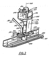
- the drive shaft 80 is coupled to an input shaft 82 of the vibratory assembly 40 by a flex joint 84 ( Fig. 2 ).
- the engine 30 additionally includes an ignition system which, in the present example, comprises a manual pull starter 85.
- the engine 30 may be power by gasoline or other fuels.
- the frame 35 includes a platform assembly 90 that is supported on the screed blade 45 by a blade adapter bracket assembly 130.
- the blade adapter bracket assembly 130 is attached to the bottom of platform assembly 90 by conventional fasteners 132 and is vibrationally separated from the frame 35 by vibrational isolators such as elastomeric shock mounts 135.
- the platform assembly 90 includes a mount plate 92 and a lift handle 94.
- the lift handle 94 includes an annular collar 98 and a grip 100 extending outwardly from the collar 98.
- the handle 94 is reversible so that the grip 100 can extend either forwardly of the screed as shown or rearward therefrom.
- the engine 30 is supported on the mount plate 92 via a lower frustoconical shaft housing 102 and a complimentary frustoconical base 104 of the clutch housing 70.
- the base 104 is attached to the upper end of the housing 102 by a clamp assembly 106.
- the vibratory assembly 40 is preferably an eccentric mass assembly rotationally coupled to the drive shaft 80 by the above-described flex joint 84 and input shaft 82.
- the exciter assembly 40 may, for instance, comprise a set of adjustable eccentric weights and one or more fixed eccentric weights (not shown).
- the exciter assembly 40 is contained within an eccentric cover 120.
- the eccentric cover 120 is attached to the underside of the blade adjuster bracket assembly 130 in a conventional manner.
- a flexible sealing ring 124 prevents concrete, dirt, and other foreign materials from invading the interior of the vibratory assembly 40.
- the screed blade 45 is generally L-shaped on cross sectional view, having a top surface, a finishing surface, a cutting edge, and trailing edge. Structural gussets 140 extend the length of the blade providing more uniform transmission of vibrational energy. Adapters may be employed to connect the blade adapter bracket assembly 130 to different shaped screed blades.
- the engine 30 is restrained from vibration by the above-described vibration restraint 20, which provides additional support to the engine 30 beyond that provided by the clamp assembly 106.
- the vibration restraint 20 preferably couples the engine 30 to the frame 35.
- a preferred vibration restraint 20 includes a plate 150 generally shaped to conform to the contours of the vibratory screed machine. Specifically, as best seen in FIGS. 4-7 , the plate 150 includes a first portion 155 aligned in a generally co-linear direction relative to a central axis 160 of the drive shaft 80, and a second portion 165 inclined with respect to the first portion 155 to conform to a narrower portion of the vibratory screed machine 25.
- the shape of the plate 150 (e.g., curvilinear, etc.) can vary.
- the plate 150 is preferably formed from steel, but could be formed from aluminum or another metal or another material entirely.
- the first portion 155 of the plate 150 terminates at a first, upper end 170, and the second portion 165 of the plate 150 terminates at a second, lower end 175.
- the first end 170 includes a pair of opening 180 configured to receive fasteners coupling the plate 155 to existing taps 185 in the engine housing 55.
- the second end 175 includes a flange portion 190 having a pair of openings 195 configured to receive fasteners coupling the plate 150 to the platform assembly 90.
- the flange 190 includes a curvilinear cutout portion 200 configured to receive a lower cylindrical end 205 of the shaft housing 102 ( FIGS. 1 and 2 ).
- the types of fasteners can vary.
- the vibration restraint 20 preferably is attached to the engine housing 55 using existing taps 185 in the engine housing 65 and is attached to the platform assembly 90 using existing fasteners on the platform assembly 90.
- additional/and or other fasteners can be used apart from the illustrated fasteners.
- Structures supplementing or replacing the plate 150 could also be used as a vibrational restraint, so long as the structure(s) provide support for the engine 30 in addition to that provided by the.clamp assembly 106.
- the vibration restraint 20 is also configured to reduce undesirable vibration on clutch housing 70 and the engine 30 caused by vibrations from the eccentric movement of the vibratory assembly 40.
- the plate 150 restrains vibration in a direction generally parallel to the central axis 160 of the drive shaft 80 but in a plane different from the drive shaft 80.
- the resultant load bearing triangulation and redundancy reduces the vibrational movement of the engine 30 and thereby enhances the engine's operating life.
- an operator can initiate start-up of the engine 30 by either activating an automatic starter or pulling the manual pull starter system.
- Clutch engagement causes the engine 30 to drive rotation of the drive shaft 80 at a standard operating speed ranging from 4,000 to 8,000 rpm, but preferably in a standard operating range of 5,000 to 6,000 rpm.
- the rotating drive shaft 80 causes the flex coupling 84 and vibratory assembly input shaft 82 to rotate.
- the shaft 82 in turn drives rotation of the adjustable eccentric weights and the fixed eccentric weights of the vibratory assembly 40, thereby imparting vibrations to the bracket blade adapter assembly 130 and thus to the screed blade 45.
- the vibration isolators 135 reduce the magnitude of vibrations transmitted to the handle assembly 50 and the operator.
- Engine speed and, hence, the frequency and intensity to the vibrations are controlled by a throttle control lever 210 attached to the handle assembly 50.
- the action of the throttle control lever 210 is transmitted to the engine 30.
- the vibrational force is transmitted through the blade adapter assembly 130 and along the screed blade 45, where structural gussets 140 strengthen blade 45 and apply the vibrational force evenly across the poured concrete.
- the vibration restraint 20 of the portable vibratory screed machine 25 is operable to reduce undesirable vibration and associated wear and extends the engine life. This response is considered adequate for operating portable vibratory screed machines.
- Tests indicate the vibration restraint 20 is operable to dramatically reduce the undesired vibration experienced by the engine 30.
- movements of both the engine 30 and the mount plate 92 were measured along x, y, z reference points 215 and 220 at the engine 30 and at the mount plate 92 of the platform assembly 90, respectively.
- Table 1 Vibration Reduction at 5,000 rpm STANDARD SCREED SCREED w/VIBRATION RESTRAINT ENGINE BASE ENGINE BASE X 2.2 1.9 2.7 2.0 Y 7.3 9.4 4.1 7.8 Z 7.5 2.8 3.1 4.0 SUM 10.7 10.0 5.8 9.0
- Table 1 Vibration Reduction at 6,000 rpm STANDARD SCREED SCREED w/VIBRATION RESTRAINT ENGINE BASE ENGINE BASE X 3.4 2.3 3.1 2.1 Y 5.6 7.0 4.0 6.3 Z 9.5 1.8 3.8 3.3 SUM 11.5 7.6 6.3 7.4
- the test results also show that the vibration restraint 20 is operable to increase the operating life of the engine 30 by a factor of two to eight times relative to the standard operating life of an engine of the same portable vibratory screed assembly without the vibration restraint 20.
- Tests were performed on portable vibratory wet screed machines configured as described above but lacking a vibration restraint and on corresponding portable vibratory wet screed machines having the vibration restraint 20.
- the engines were operated at a standard operating speed of 5,000 to 6,000 rpm, and the blades were submerged in foam and water to simulate concrete.
- the types of machines tested varied in length of screed blade (e.g., 6 foot to 10 foot i.e.
Landscapes
- Engineering & Computer Science (AREA)
- Architecture (AREA)
- Mechanical Engineering (AREA)
- Civil Engineering (AREA)
- Structural Engineering (AREA)
- Road Paving Machines (AREA)
- Apparatuses For Generation Of Mechanical Vibrations (AREA)
Applications Claiming Priority (2)
| Application Number | Priority Date | Filing Date | Title |
|---|---|---|---|
| US10/773,012 US7052204B2 (en) | 2004-02-04 | 2004-02-04 | Portable vibratory screed with vibration restraint |
| US773012 | 2004-02-04 |
Publications (3)
| Publication Number | Publication Date |
|---|---|
| EP1561882A2 EP1561882A2 (en) | 2005-08-10 |
| EP1561882A3 EP1561882A3 (en) | 2008-02-27 |
| EP1561882B1 true EP1561882B1 (en) | 2011-05-25 |
Family
ID=34679388
Family Applications (1)
| Application Number | Title | Priority Date | Filing Date |
|---|---|---|---|
| EP05002192A Expired - Lifetime EP1561882B1 (en) | 2004-02-04 | 2005-02-02 | Portable vibratory screed with vibration restraint |
Country Status (9)
| Country | Link |
|---|---|
| US (1) | US7052204B2 (https=) |
| EP (1) | EP1561882B1 (https=) |
| JP (1) | JP4774480B2 (https=) |
| CN (1) | CN100420818C (https=) |
| AT (1) | ATE510979T1 (https=) |
| CA (1) | CA2496061C (https=) |
| ES (1) | ES2367116T3 (https=) |
| HK (1) | HK1078116B (https=) |
| MX (1) | MXPA05001443A (https=) |
Families Citing this family (28)
| Publication number | Priority date | Publication date | Assignee | Title |
|---|---|---|---|---|
| CA2475525A1 (en) * | 2004-07-22 | 2006-01-22 | Magic Screed (9033-4624 Quebec Inc.) | Vibrating screed having slidable handles, flexible seal and a double bearing |
| US7156577B1 (en) * | 2005-06-01 | 2007-01-02 | Rozinski Richard M | Concrete finishing tool with handle-mounted vibrating arrangement |
| US20060291958A1 (en) * | 2005-06-28 | 2006-12-28 | Pirandello Industries Ltd. | Leveling blade, vibrating screed including the blade, and kit for assembling the same |
| US8608402B2 (en) | 2005-06-28 | 2013-12-17 | Settimio Argento | Leveling blade, vibrating screed including the blade, and kit for assembling the same |
| CN101535570A (zh) * | 2006-06-15 | 2009-09-16 | 威克纽森股份有限公司 | 带有气泡管倾斜指示系统的轻便型振动式整平板 |
| EP2027341A2 (en) * | 2006-06-15 | 2009-02-25 | Wacker Neuson Corporation | Portable vibratory screed with bubble vial inclination indication system |
| CA2686358A1 (en) * | 2008-11-26 | 2010-05-26 | 2544-9455 Quebec Inc. | Vibration reducing link for vibrating screed |
| US8469113B2 (en) * | 2009-08-20 | 2013-06-25 | Schiller Ground Care, Inc. | Earthworking machine |
| US8104992B2 (en) * | 2009-10-19 | 2012-01-31 | Richard Biodrowski | Concrete screed apparatus |
| CN101798873B (zh) * | 2010-03-15 | 2011-06-22 | 魏勇 | 一种现浇式楼板混凝土浇注一次成型的装置及施工方法 |
| US8366345B1 (en) | 2010-08-16 | 2013-02-05 | Henry Copeland | Powered screed machine |
| USD685395S1 (en) * | 2011-03-24 | 2013-07-02 | Wacker Neuson Production Americas Llc | Handle mount |
| US20150022040A1 (en) * | 2013-07-22 | 2015-01-22 | Frank Mikowychok | Vibration imparting device for a concrete finishing tool |
| EP3094451B1 (en) * | 2014-01-14 | 2023-06-07 | Temple Allen Holdings LLC | Reduced-vibration surface treatment device |
| CN103835509A (zh) * | 2014-02-25 | 2014-06-04 | 王迎军 | 一种带有防震装置的混凝土振平尺 |
| CN104164825B (zh) * | 2014-08-28 | 2016-04-20 | 成都来宝石油设备有限公司 | 易搬运平板夯 |
| WO2017087577A1 (en) * | 2015-11-16 | 2017-05-26 | Baron Innovative Technologies Lp | Float, float assemblies, float adapters and interfaces, float vibration apparatus, and groovers and methods |
| CN107217852B (zh) * | 2017-07-11 | 2019-06-28 | 湖北长江路桥股份有限公司 | 一种混凝土摊铺用整平装置 |
| KR102194969B1 (ko) * | 2019-03-27 | 2020-12-24 | 송영철 | 콘크리트 평탄화 다짐기 |
| CN110878507A (zh) * | 2019-12-05 | 2020-03-13 | 中冶天工集团天津有限公司 | 一种简易坡度地坪找平振捣一体化装置及其施工方法 |
| EP4100576A4 (en) * | 2020-02-04 | 2024-03-27 | Baron Innovative Technology LP | FLEANER, FLEANER ASSEMBLIES, FLEANER INTERFACES AND ADAPTERS, VIBRATION APPARATUS, AND GROOVING IRONS AND METHODS |
| CN111350363A (zh) * | 2020-04-11 | 2020-06-30 | 张祖忠 | 一种混凝土振平覆膜设备 |
| CN111719391B (zh) * | 2020-06-29 | 2022-05-20 | 江苏绿科人居智能制造科技有限责任公司 | 一种自适应反作用力缓冲吸收的水泥平推板 |
| US12065790B2 (en) | 2020-07-07 | 2024-08-20 | Milwaukee Electric Tool Corporation | Plate compactor |
| EP4179150A4 (en) | 2020-07-07 | 2024-09-04 | Milwaukee Electric Tool Corporation | PLATE COMPACTOR |
| WO2022035959A1 (en) | 2020-08-11 | 2022-02-17 | Milwaukee Electric Tool Corporation | Vibrating screed |
| CN113235888B (zh) * | 2021-05-06 | 2022-06-24 | 苏州方石科技有限公司 | 地面整平机器人及地面整平机器人的控制方法 |
| US12460431B2 (en) | 2022-05-13 | 2025-11-04 | Bad Ass Tools Llc | Concrete screed device with oscillating screed bar |
Family Cites Families (16)
| Publication number | Priority date | Publication date | Assignee | Title |
|---|---|---|---|---|
| US4213749A (en) * | 1978-03-06 | 1980-07-22 | Morrison Donald R | Portable vibrating concrete screed |
| US4340351A (en) * | 1981-02-13 | 1982-07-20 | Owens Joe M | Vibratory concrete screed with eccentric drive shaft |
| US4386901A (en) * | 1981-03-23 | 1983-06-07 | Morrison Donald R | Portable vibrating concrete screed |
| JPS6294653A (ja) * | 1985-10-21 | 1987-05-01 | 島袋 良信 | 床コンクリ−ト均し機 |
| US5244305A (en) * | 1990-11-29 | 1993-09-14 | Lindley Thomas R | Concrete striking equipment |
| US5345684A (en) * | 1993-01-25 | 1994-09-13 | Wci Outdoor Products, Inc. | Flexible line trimmer having an anti-vibration handle |
| CN2254458Y (zh) * | 1996-05-08 | 1997-05-21 | 巴庆江 | 自动抹灰机 |
| US5857803A (en) * | 1997-02-26 | 1999-01-12 | Davis; Larry L. | Portable vibratory wet screed |
| BE1011313A3 (nl) * | 1997-08-05 | 1999-07-06 | B Mac Besloten Vennootschap Me | Triltoestel voor het bewerken van een vloerlaag en werkwijze voor de constructie ervan. |
| US5984571A (en) * | 1997-10-31 | 1999-11-16 | Cleform Tool Company | Vibrating screed |
| US6089787A (en) * | 1998-05-26 | 2000-07-18 | Allen Engineering Corp. | Transformable two-person floating screed with automatic grade control |
| CA2261508C (en) * | 1999-02-12 | 2002-06-11 | Les Betons Roger Rouillard Inc. | Vibrating screed for surfacing concrete |
| US6296467B1 (en) * | 1999-02-16 | 2001-10-02 | Les Betons Roger Rouillard Inc. | Vibrating screed for surfacing concrete |
| CN2382748Y (zh) * | 1999-05-14 | 2000-06-14 | 刘海涛 | 自动排式振捣机 |
| JP2001115648A (ja) * | 1999-10-19 | 2001-04-24 | Tokimec Jido Kenki:Kk | コンクリート均し機 |
| DE20105768U1 (de) * | 2001-03-30 | 2001-06-21 | BOMAG GmbH & Co. oHG, 56154 Boppard | Vibrationsstampfer |
-
2004
- 2004-02-04 US US10/773,012 patent/US7052204B2/en not_active Expired - Lifetime
-
2005
- 2005-02-02 AT AT05002192T patent/ATE510979T1/de not_active IP Right Cessation
- 2005-02-02 EP EP05002192A patent/EP1561882B1/en not_active Expired - Lifetime
- 2005-02-02 ES ES05002192T patent/ES2367116T3/es not_active Expired - Lifetime
- 2005-02-04 CN CNB2005100656420A patent/CN100420818C/zh not_active Expired - Fee Related
- 2005-02-04 JP JP2005028773A patent/JP4774480B2/ja not_active Expired - Fee Related
- 2005-02-04 MX MXPA05001443A patent/MXPA05001443A/es active IP Right Grant
- 2005-02-04 CA CA2496061A patent/CA2496061C/en not_active Expired - Fee Related
-
2006
- 2006-01-05 HK HK06100237.7A patent/HK1078116B/en not_active IP Right Cessation
Also Published As
| Publication number | Publication date |
|---|---|
| CN1757859A (zh) | 2006-04-12 |
| CN100420818C (zh) | 2008-09-24 |
| MXPA05001443A (es) | 2005-09-30 |
| EP1561882A3 (en) | 2008-02-27 |
| CA2496061C (en) | 2012-03-20 |
| ATE510979T1 (de) | 2011-06-15 |
| ES2367116T3 (es) | 2011-10-28 |
| JP2005220738A (ja) | 2005-08-18 |
| US7052204B2 (en) | 2006-05-30 |
| JP4774480B2 (ja) | 2011-09-14 |
| HK1078116A1 (en) | 2006-03-03 |
| HK1078116B (en) | 2011-09-16 |
| US20050169707A1 (en) | 2005-08-04 |
| EP1561882A2 (en) | 2005-08-10 |
| CA2496061A1 (en) | 2005-08-04 |
Similar Documents
| Publication | Publication Date | Title |
|---|---|---|
| EP1561882B1 (en) | Portable vibratory screed with vibration restraint | |
| US5857803A (en) | Portable vibratory wet screed | |
| US6200065B1 (en) | Lightweight, portable vibratory screed | |
| US4386901A (en) | Portable vibrating concrete screed | |
| AU2008203038B2 (en) | Lightweight apparatus for screeding and vibrating uncured concrete surfaces | |
| US5375942A (en) | Material-leveling apparatus | |
| US6296467B1 (en) | Vibrating screed for surfacing concrete | |
| US4213749A (en) | Portable vibrating concrete screed | |
| US6129481A (en) | Screed assembly and oscillating member kit therefor | |
| US7540688B1 (en) | Breakdown screed plate | |
| EP0663493A1 (en) | A riding trowel | |
| EP2233640A2 (en) | Portable vibratory laser screed with remote grade indicator and folding handles | |
| AU2002334922A1 (en) | Lightweight apparatus for screeding and vibrating uncured concrete surfaces | |
| CN102729314A (zh) | 具有减振手柄安装架的手动操作的振动器 | |
| US20230366218A1 (en) | Concrete screed device with oscillating screed bar | |
| US5713637A (en) | Floor covering removal apparatus | |
| US7156577B1 (en) | Concrete finishing tool with handle-mounted vibrating arrangement | |
| CA2261508C (en) | Vibrating screed for surfacing concrete | |
| JPS63184663A (ja) | 床コンクリ−ト均し機 | |
| JPH09195512A (ja) | 浮子付きコンクリートバイブレータ | |
| CA1141578A (en) | Winch apparatus for vibrating concrete screed | |
| JPS6126872Y2 (https=) |
Legal Events
| Date | Code | Title | Description |
|---|---|---|---|
| PUAI | Public reference made under article 153(3) epc to a published international application that has entered the european phase |
Free format text: ORIGINAL CODE: 0009012 |
|
| AK | Designated contracting states |
Kind code of ref document: A2 Designated state(s): AT BE BG CH CY CZ DE DK EE ES FI FR GB GR HU IE IS IT LI LT LU MC NL PL PT RO SE SI SK TR |
|
| AX | Request for extension of the european patent |
Extension state: AL BA HR LV MK YU |
|
| REG | Reference to a national code |
Ref country code: HK Ref legal event code: DE Ref document number: 1078116 Country of ref document: HK |
|
| PUAL | Search report despatched |
Free format text: ORIGINAL CODE: 0009013 |
|
| AK | Designated contracting states |
Kind code of ref document: A3 Designated state(s): AT BE BG CH CY CZ DE DK EE ES FI FR GB GR HU IE IS IT LI LT LU MC NL PL PT RO SE SI SK TR |
|
| AX | Request for extension of the european patent |
Extension state: AL BA HR LV MK YU |
|
| 17P | Request for examination filed |
Effective date: 20080703 |
|
| 17Q | First examination report despatched |
Effective date: 20080902 |
|
| AKX | Designation fees paid |
Designated state(s): AT BE BG CH CY CZ DE DK EE ES FI FR GB GR HU IE IS IT LI LT LU MC NL PL PT RO SE SI SK TR |
|
| GRAP | Despatch of communication of intention to grant a patent |
Free format text: ORIGINAL CODE: EPIDOSNIGR1 |
|
| GRAS | Grant fee paid |
Free format text: ORIGINAL CODE: EPIDOSNIGR3 |
|
| GRAA | (expected) grant |
Free format text: ORIGINAL CODE: 0009210 |
|
| AK | Designated contracting states |
Kind code of ref document: B1 Designated state(s): AT BE BG CH CY CZ DE DK EE ES FI FR GB GR HU IE IS IT LI LT LU MC NL PL PT RO SE SI SK TR |
|
| REG | Reference to a national code |
Ref country code: GB Ref legal event code: FG4D |
|
| REG | Reference to a national code |
Ref country code: CH Ref legal event code: EP |
|
| RAP2 | Party data changed (patent owner data changed or rights of a patent transferred) |
Owner name: WACKER NEUSON CORPORATION |
|
| REG | Reference to a national code |
Ref country code: IE Ref legal event code: FG4D |
|
| REG | Reference to a national code |
Ref country code: DE Ref legal event code: R096 Ref document number: 602005028193 Country of ref document: DE Effective date: 20110707 |
|
| REG | Reference to a national code |
Ref country code: SE Ref legal event code: TRGR |
|
| REG | Reference to a national code |
Ref country code: HK Ref legal event code: GR Ref document number: 1078116 Country of ref document: HK |
|
| REG | Reference to a national code |
Ref country code: NL Ref legal event code: VDEP Effective date: 20110525 |
|
| RAP2 | Party data changed (patent owner data changed or rights of a patent transferred) |
Owner name: WACKER NEUSON PRODUCTION AMERICAS LLC |
|
| REG | Reference to a national code |
Ref country code: ES Ref legal event code: FG2A Ref document number: 2367116 Country of ref document: ES Kind code of ref document: T3 Effective date: 20111028 |
|
| PG25 | Lapsed in a contracting state [announced via postgrant information from national office to epo] |
Ref country code: PT Free format text: LAPSE BECAUSE OF FAILURE TO SUBMIT A TRANSLATION OF THE DESCRIPTION OR TO PAY THE FEE WITHIN THE PRESCRIBED TIME-LIMIT Effective date: 20110926 Ref country code: LT Free format text: LAPSE BECAUSE OF FAILURE TO SUBMIT A TRANSLATION OF THE DESCRIPTION OR TO PAY THE FEE WITHIN THE PRESCRIBED TIME-LIMIT Effective date: 20110525 |
|
| PG25 | Lapsed in a contracting state [announced via postgrant information from national office to epo] |
Ref country code: SI Free format text: LAPSE BECAUSE OF FAILURE TO SUBMIT A TRANSLATION OF THE DESCRIPTION OR TO PAY THE FEE WITHIN THE PRESCRIBED TIME-LIMIT Effective date: 20110525 Ref country code: IS Free format text: LAPSE BECAUSE OF FAILURE TO SUBMIT A TRANSLATION OF THE DESCRIPTION OR TO PAY THE FEE WITHIN THE PRESCRIBED TIME-LIMIT Effective date: 20110925 Ref country code: BE Free format text: LAPSE BECAUSE OF FAILURE TO SUBMIT A TRANSLATION OF THE DESCRIPTION OR TO PAY THE FEE WITHIN THE PRESCRIBED TIME-LIMIT Effective date: 20110525 Ref country code: AT Free format text: LAPSE BECAUSE OF FAILURE TO SUBMIT A TRANSLATION OF THE DESCRIPTION OR TO PAY THE FEE WITHIN THE PRESCRIBED TIME-LIMIT Effective date: 20110525 Ref country code: CY Free format text: LAPSE BECAUSE OF FAILURE TO SUBMIT A TRANSLATION OF THE DESCRIPTION OR TO PAY THE FEE WITHIN THE PRESCRIBED TIME-LIMIT Effective date: 20110525 Ref country code: FI Free format text: LAPSE BECAUSE OF FAILURE TO SUBMIT A TRANSLATION OF THE DESCRIPTION OR TO PAY THE FEE WITHIN THE PRESCRIBED TIME-LIMIT Effective date: 20110525 Ref country code: GR Free format text: LAPSE BECAUSE OF FAILURE TO SUBMIT A TRANSLATION OF THE DESCRIPTION OR TO PAY THE FEE WITHIN THE PRESCRIBED TIME-LIMIT Effective date: 20110826 |
|
| REG | Reference to a national code |
Ref country code: GB Ref legal event code: 732E Free format text: REGISTERED BETWEEN 20111117 AND 20111123 |
|
| PG25 | Lapsed in a contracting state [announced via postgrant information from national office to epo] |
Ref country code: NL Free format text: LAPSE BECAUSE OF FAILURE TO SUBMIT A TRANSLATION OF THE DESCRIPTION OR TO PAY THE FEE WITHIN THE PRESCRIBED TIME-LIMIT Effective date: 20110525 |
|
| REG | Reference to a national code |
Ref country code: DE Ref legal event code: R081 Ref document number: 602005028193 Country of ref document: DE Owner name: WACKER NEUSON PRODUCTION AMERICAS LLC, MENOMON, US Free format text: FORMER OWNER: WACKER CORP., MENOMONEE FALLS, WIS., US Effective date: 20111115 Ref country code: DE Ref legal event code: R081 Ref document number: 602005028193 Country of ref document: DE Owner name: WACKER NEUSON PRODUCTION AMERICAS LLC, US Free format text: FORMER OWNER: WACKER CORP., MENOMONEE FALLS, US Effective date: 20111115 |
|
| PG25 | Lapsed in a contracting state [announced via postgrant information from national office to epo] |
Ref country code: EE Free format text: LAPSE BECAUSE OF FAILURE TO SUBMIT A TRANSLATION OF THE DESCRIPTION OR TO PAY THE FEE WITHIN THE PRESCRIBED TIME-LIMIT Effective date: 20110525 Ref country code: CZ Free format text: LAPSE BECAUSE OF FAILURE TO SUBMIT A TRANSLATION OF THE DESCRIPTION OR TO PAY THE FEE WITHIN THE PRESCRIBED TIME-LIMIT Effective date: 20110525 |
|
| PG25 | Lapsed in a contracting state [announced via postgrant information from national office to epo] |
Ref country code: PL Free format text: LAPSE BECAUSE OF FAILURE TO SUBMIT A TRANSLATION OF THE DESCRIPTION OR TO PAY THE FEE WITHIN THE PRESCRIBED TIME-LIMIT Effective date: 20110525 Ref country code: RO Free format text: LAPSE BECAUSE OF FAILURE TO SUBMIT A TRANSLATION OF THE DESCRIPTION OR TO PAY THE FEE WITHIN THE PRESCRIBED TIME-LIMIT Effective date: 20110525 Ref country code: DK Free format text: LAPSE BECAUSE OF FAILURE TO SUBMIT A TRANSLATION OF THE DESCRIPTION OR TO PAY THE FEE WITHIN THE PRESCRIBED TIME-LIMIT Effective date: 20110525 Ref country code: SK Free format text: LAPSE BECAUSE OF FAILURE TO SUBMIT A TRANSLATION OF THE DESCRIPTION OR TO PAY THE FEE WITHIN THE PRESCRIBED TIME-LIMIT Effective date: 20110525 |
|
| PLBE | No opposition filed within time limit |
Free format text: ORIGINAL CODE: 0009261 |
|
| STAA | Information on the status of an ep patent application or granted ep patent |
Free format text: STATUS: NO OPPOSITION FILED WITHIN TIME LIMIT |
|
| 26N | No opposition filed |
Effective date: 20120228 |
|
| PG25 | Lapsed in a contracting state [announced via postgrant information from national office to epo] |
Ref country code: IT Free format text: LAPSE BECAUSE OF FAILURE TO SUBMIT A TRANSLATION OF THE DESCRIPTION OR TO PAY THE FEE WITHIN THE PRESCRIBED TIME-LIMIT Effective date: 20110525 |
|
| REG | Reference to a national code |
Ref country code: DE Ref legal event code: R097 Ref document number: 602005028193 Country of ref document: DE Effective date: 20120228 |
|
| PGFP | Annual fee paid to national office [announced via postgrant information from national office to epo] |
Ref country code: SE Payment date: 20120221 Year of fee payment: 8 Ref country code: GB Payment date: 20120222 Year of fee payment: 8 |
|
| PG25 | Lapsed in a contracting state [announced via postgrant information from national office to epo] |
Ref country code: MC Free format text: LAPSE BECAUSE OF NON-PAYMENT OF DUE FEES Effective date: 20120229 |
|
| REG | Reference to a national code |
Ref country code: CH Ref legal event code: PL |
|
| PG25 | Lapsed in a contracting state [announced via postgrant information from national office to epo] |
Ref country code: CH Free format text: LAPSE BECAUSE OF NON-PAYMENT OF DUE FEES Effective date: 20120229 Ref country code: LI Free format text: LAPSE BECAUSE OF NON-PAYMENT OF DUE FEES Effective date: 20120229 |
|
| REG | Reference to a national code |
Ref country code: IE Ref legal event code: MM4A |
|
| REG | Reference to a national code |
Ref country code: FR Ref legal event code: ST Effective date: 20121031 |
|
| PG25 | Lapsed in a contracting state [announced via postgrant information from national office to epo] |
Ref country code: FR Free format text: LAPSE BECAUSE OF NON-PAYMENT OF DUE FEES Effective date: 20120229 Ref country code: IE Free format text: LAPSE BECAUSE OF NON-PAYMENT OF DUE FEES Effective date: 20120202 |
|
| PG25 | Lapsed in a contracting state [announced via postgrant information from national office to epo] |
Ref country code: BG Free format text: LAPSE BECAUSE OF FAILURE TO SUBMIT A TRANSLATION OF THE DESCRIPTION OR TO PAY THE FEE WITHIN THE PRESCRIBED TIME-LIMIT Effective date: 20110825 |
|
| PGFP | Annual fee paid to national office [announced via postgrant information from national office to epo] |
Ref country code: ES Payment date: 20120221 Year of fee payment: 8 |
|
| REG | Reference to a national code |
Ref country code: SE Ref legal event code: EUG |
|
| GBPC | Gb: european patent ceased through non-payment of renewal fee |
Effective date: 20130202 |
|
| PG25 | Lapsed in a contracting state [announced via postgrant information from national office to epo] |
Ref country code: SE Free format text: LAPSE BECAUSE OF NON-PAYMENT OF DUE FEES Effective date: 20130203 |
|
| PG25 | Lapsed in a contracting state [announced via postgrant information from national office to epo] |
Ref country code: GB Free format text: LAPSE BECAUSE OF NON-PAYMENT OF DUE FEES Effective date: 20130202 |
|
| REG | Reference to a national code |
Ref country code: ES Ref legal event code: FD2A Effective date: 20140409 |
|
| PG25 | Lapsed in a contracting state [announced via postgrant information from national office to epo] |
Ref country code: TR Free format text: LAPSE BECAUSE OF FAILURE TO SUBMIT A TRANSLATION OF THE DESCRIPTION OR TO PAY THE FEE WITHIN THE PRESCRIBED TIME-LIMIT Effective date: 20110525 |
|
| PG25 | Lapsed in a contracting state [announced via postgrant information from national office to epo] |
Ref country code: LU Free format text: LAPSE BECAUSE OF NON-PAYMENT OF DUE FEES Effective date: 20120202 |
|
| PG25 | Lapsed in a contracting state [announced via postgrant information from national office to epo] |
Ref country code: HU Free format text: LAPSE BECAUSE OF FAILURE TO SUBMIT A TRANSLATION OF THE DESCRIPTION OR TO PAY THE FEE WITHIN THE PRESCRIBED TIME-LIMIT Effective date: 20050202 |
|
| PG25 | Lapsed in a contracting state [announced via postgrant information from national office to epo] |
Ref country code: ES Free format text: LAPSE BECAUSE OF NON-PAYMENT OF DUE FEES Effective date: 20130203 |
|
| PGFP | Annual fee paid to national office [announced via postgrant information from national office to epo] |
Ref country code: DE Payment date: 20150225 Year of fee payment: 11 |
|
| REG | Reference to a national code |
Ref country code: DE Ref legal event code: R119 Ref document number: 602005028193 Country of ref document: DE |
|
| PG25 | Lapsed in a contracting state [announced via postgrant information from national office to epo] |
Ref country code: DE Free format text: LAPSE BECAUSE OF NON-PAYMENT OF DUE FEES Effective date: 20160901 |