EP1561660A1 - Höhenverstellbare Stütze für Sattelauflieger oder dergleichen - Google Patents
Höhenverstellbare Stütze für Sattelauflieger oder dergleichen Download PDFInfo
- Publication number
- EP1561660A1 EP1561660A1 EP04026403A EP04026403A EP1561660A1 EP 1561660 A1 EP1561660 A1 EP 1561660A1 EP 04026403 A EP04026403 A EP 04026403A EP 04026403 A EP04026403 A EP 04026403A EP 1561660 A1 EP1561660 A1 EP 1561660A1
- Authority
- EP
- European Patent Office
- Prior art keywords
- support
- drive shaft
- tube
- support according
- bearing
- Prior art date
- Legal status (The legal status is an assumption and is not a legal conclusion. Google has not performed a legal analysis and makes no representation as to the accuracy of the status listed.)
- Granted
Links
- 230000005540 biological transmission Effects 0.000 claims description 8
- 238000006073 displacement reaction Methods 0.000 claims description 2
- 238000010276 construction Methods 0.000 description 4
- 230000006835 compression Effects 0.000 description 2
- 238000007906 compression Methods 0.000 description 2
- 230000004913 activation Effects 0.000 description 1
- 230000001419 dependent effect Effects 0.000 description 1
- 238000005553 drilling Methods 0.000 description 1
- 238000005096 rolling process Methods 0.000 description 1
- 230000008719 thickening Effects 0.000 description 1
Images


Classifications
-
- B—PERFORMING OPERATIONS; TRANSPORTING
- B60—VEHICLES IN GENERAL
- B60S—SERVICING, CLEANING, REPAIRING, SUPPORTING, LIFTING, OR MANOEUVRING OF VEHICLES, NOT OTHERWISE PROVIDED FOR
- B60S9/00—Ground-engaging vehicle fittings for supporting, lifting, or manoeuvring the vehicle, wholly or in part, e.g. built-in jacks
- B60S9/02—Ground-engaging vehicle fittings for supporting, lifting, or manoeuvring the vehicle, wholly or in part, e.g. built-in jacks for only lifting or supporting
- B60S9/04—Ground-engaging vehicle fittings for supporting, lifting, or manoeuvring the vehicle, wholly or in part, e.g. built-in jacks for only lifting or supporting mechanically
- B60S9/06—Ground-engaging vehicle fittings for supporting, lifting, or manoeuvring the vehicle, wholly or in part, e.g. built-in jacks for only lifting or supporting mechanically of screw-and-nut type
- B60S9/08—Ground-engaging vehicle fittings for supporting, lifting, or manoeuvring the vehicle, wholly or in part, e.g. built-in jacks for only lifting or supporting mechanically of screw-and-nut type the screw axis being substantially vertical
Definitions
- the invention relates to a height-adjustable support for Semitrailer or the like according to the preamble of Claim 1.
- Such supports are, usually in pairs, at the front Area of the semitrailer arranged.
- a generic support is known from DE 203 07 381 U1 known.
- the hand drive shaft is behind the manual drive pinion in a warehouse in the middle area of the column outer tube is arranged and a bearing in the front wall deposited.
- the manual drive is the manual drive shaft, after axial displacement, in addition to a front-side journals in front of the manual drive pinion in the rear wall stored the support outer tube.
- the middle camp requires a certain amount of construction work.
- the invention is based on the object, a support for semi-trailer with a simpler storage of the drive shaft too create, which is constructive and cost optimal.
- the drive shaft at least in its front End region, i. in the end area located in the column outer tube is concentric hollow and on one fixed cylindrical bearing pin, the inside of the Rear wall of the outer support tube sits to store.
- a second Storage may be in a bearing body which is in the front wall of the Support outer tube sits done.
- a front-side introduced bearing bore described depth in the drive shaft can advantageously also a hollow pinion z. B. on a front-side pin of the drive shaft and is connected to this and the other inner area is used for storage on the bearing journal, find use. It may also be advantageous to make the entire drive shaft from a tube.
- Another idea is to use the bearing body for storage Drive shaft in the front wall of the column outer tube so too shape it from the inside into the outer support tube and can be flanged and screwed only from the outside is what makes the construction of the support more compact.
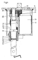
- the support 10 shown in Fig. 1 to 5 is in pairs on the chassis a semitrailer is mounted in the front area and is retracted into transport position, i. in shortened condition. Before the semi-trailer is disconnected from the semi-trailer, the supports 10 are extended.
- the support 10 has a support outer tube 12 and a longitudinally displaceable therein stored inner tube 13.
- the outer support tube 12 and the inner support tube 13 have a square cross section.
- the support 10 is with a on its back over an am Support outer tube 12 seated mounting plate 14 am Fixed semi-trailer.
- a wegschwenkbare Hand crank 16 for manual drive.
- the support 10 has a spindle 17 which moves a nut on the support inner tube 13 is fixed, on.
- the spindle drive is supported via a thrust bearing against a bearing plate From 18, the horizontally welded into the outer support tube 12 is.
- a bearing plate From 18 About the bearing plate 18 is located on a Spigot of the spindle 17 with this pinned bevel gear 19th
- a Transmission output shaft 20 arranged horizontally, in the Pipe walls of the support outer tube 12 is mounted.
- the drive shaft 24 has a thickening in the inner end region on, which is designed as a gear 25. And in the same end area the drive shaft 24 has a concentric bearing bore 26, whose depth is about twice the width of the gear 25th equivalent.
- a collar bushing 30 In the bearing body 29 is a collar bushing 30, the inside having two axially spaced semi-circular radial grooves 31, 32.
- the drive shaft 24 is on the bearing pin 28 and in Bearing body 29 stored and can for the purpose of switching on and off be moved axially of the manual drive.
- the sliding path of the drive shaft 24 is slightly more than the Tooth width of their gear 25 and is of a on the Drive shaft 24 seated collar 33 limited to the outside.
- Fig. 3 shows the drive shaft 24 in the switching position at the Gear 25 is in engagement with the gear 22 and the axial Arresting takes place in the radial groove 31.
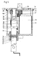
- Fig. 5 is a separate pinion 36 on a trunnion 37 of the drive shaft 24 up / attached and with this means a clamping pin 38 pinned.
- the pinion 33 has a concentric bore 39, in the a bearing bush 40 is seated and is on the bearing pin 28th deposited.
Landscapes
- Engineering & Computer Science (AREA)
- Mechanical Engineering (AREA)
- Vehicle Cleaning, Maintenance, Repair, Refitting, And Outriggers (AREA)
- Arrangement And Driving Of Transmission Devices (AREA)
- Gear Transmission (AREA)
- Vehicle Body Suspensions (AREA)
- Transition And Organic Metals Composition Catalysts For Addition Polymerization (AREA)
- Spinning Or Twisting Of Yarns (AREA)
- Machines For Laying And Maintaining Railways (AREA)
- Road Signs Or Road Markings (AREA)
- Braking Arrangements (AREA)
- Shafts, Cranks, Connecting Bars, And Related Bearings (AREA)
Abstract
Description
Es kann auch vorteilhaft sein die ganze Antriebswelle aus einem Rohr herzustellen.
- Fig. 1
- eine Frontansicht der erfindungsgemäßen Stütze,
- Fig. 2
- eine Seitenansicht der in Fig. 1 gezeigten Stütze,
- Fig. 3
- einen Querschnitt der Stütze entlang der Linie A-A in Fig. 1 mit der Antriebswelle in Funktionsstellung,
- Fig. 4
- einen Querschnitt der Stütze entlang der Linie A-A in Fig. 1 mit der Antriebswellenstellung außer Funktion und
- Fig. 5
- einen Querschnitt der Stütze entlang der Linie A-A entsprechend Fig. 3 in alternativer Ausgestaltung der Antriebswelle.
- 10
- Stütze
- 11
- Verbindungswelle
- 12
- Stützenaußenrohr
- 13
- Stützeninnenrohr
- 14
- Anschraubplatte
- 15
- Fuß
- 16
- Handkurbel
- 17
- Spindel
- 18
- Lagerplatte
- 19
- Kegelrad
- 20
- Getriebeausgangswelle
- 21
- Kegelrad
- 22
- Zahnrad
- 23
- Motor
- 24
- Antriebswelle
- 25
- Zahnrad
- 26
- Lagerbohrung
- 27
- Buchse
- 28
- Lagerungszapfen
- 29
- Lagerkörper
- 30
- Bundbuchse
- 31
- Radialnut
- 32
- Radialnut
- 33
- Stellring
- 34
- Kugel
- 35
- Druckfeder
- 36
- Zahnritzel
- 37
- Stirnzapfen
- 38
- Spannstift
- 39
- Bohrung
- 40
- Lagerbuchse
Claims (8)
- Höhenverstellbare Stütze für Sattelauflieger oder dergleichen mit einem ortsfest angebrachten Stützenaußenrohr, einem darin längsverschiebbar angeordneten Stützeninnenrohr und einer Getriebeausgangswelle auf der ein durchmesserkleineres Kegelrad drehfest sitzt, das zu einer Kegelradgetriebestufe gehört, die den Spindeltrieb zwecks Verschiebung des Stützeninnenrohres antreibt, dadurch gekennzeichnet, dass die Antriebswelle (24) zumindest in ihrem, der Antriebseite entgegengesetzten Endbereich hohl ist, oder einen daran angebrachten Fortsatz aufweist der hohl ist.
- Stütze nach Anspruch 1, dadurch gekennzeichnet, dass der Fortsatz ein drehfest an der Antriebswelle (24) sitzendes Zahnrad (25) bzw. ein Ritzel ist.
- Stütze nach Anspruch 1, dadurch gekennzeichnet, dass der hohle Bereich eine konzentrische Lagerbohrung (26) ist.
- Stütze nach Anspruch 1, dadurch gekennzeichnet, dass an der Rückseite des Stützenaußenrohres (12) ein nach innen weisender Lagerungszapfen (28) vorhanden ist, auf dem die Antriebswelle (24) mit ihrer Lagerbohrung (26) gelagert ist und axial verschiebbar oder axial festgelegt sein kann.
- Stütze nach Anspruch 1 und 4, dadurch gekennzeichnet, dass das Zahnrad (25) bzw. Ritzel auf dem Lagerungszapfen (28) lagert.
- Stütze nach Anspruch 1, dadurch gekennzeichnet, dass der Lagerkörper (29) von innen in die Vorderwand des Stützenaußenrohres (12) eingesetzt und angeflanscht und von außen angeschraubt ist.
- Stütze nach Anspruch 1 und 6, dadurch gekennzeichnet, dass der Lagerkörper (29) hauptsächlich oberhalb und unterhalb der Antriebs welle (24) abstehende Flanschbereiche zur Befestigung aufweist.
- Stütze nach Anspruch 1, dadurch gekennzeichnet, dass die Antriebswelle (24) als Rohr ausgebildet ist.
Priority Applications (1)
| Application Number | Priority Date | Filing Date | Title |
|---|---|---|---|
| PL04026403T PL1561660T3 (pl) | 2004-02-05 | 2004-11-06 | Wspornik o regulowanej wysokości dla naczepy siodłowej lub podobnego urządzenia |
Applications Claiming Priority (2)
| Application Number | Priority Date | Filing Date | Title |
|---|---|---|---|
| DE202004001707U DE202004001707U1 (de) | 2004-02-05 | 2004-02-05 | Höhenverstellbare Stütze für Sattelauflieger o.dgl. |
| DE202004001707U | 2004-02-05 |
Publications (2)
| Publication Number | Publication Date |
|---|---|
| EP1561660A1 true EP1561660A1 (de) | 2005-08-10 |
| EP1561660B1 EP1561660B1 (de) | 2007-02-28 |
Family
ID=32520444
Family Applications (1)
| Application Number | Title | Priority Date | Filing Date |
|---|---|---|---|
| EP04026403A Expired - Lifetime EP1561660B1 (de) | 2004-02-05 | 2004-11-06 | Höhenverstellbare Stütze für Sattelauflieger oder dergleichen |
Country Status (7)
| Country | Link |
|---|---|
| US (1) | US7083196B2 (de) |
| EP (1) | EP1561660B1 (de) |
| CN (1) | CN1651291B (de) |
| AT (1) | ATE355206T1 (de) |
| DE (2) | DE202004001707U1 (de) |
| ES (1) | ES2280881T3 (de) |
| PL (1) | PL1561660T3 (de) |
Families Citing this family (19)
| Publication number | Priority date | Publication date | Assignee | Title |
|---|---|---|---|---|
| DE202004000592U1 (de) * | 2004-01-16 | 2004-04-29 | Riedl, Reinhold, Dipl.-Ing. | Höhenverstellbare Stütze für Sattelauflieger o.dgl. |
| US20060113453A1 (en) * | 2004-11-29 | 2006-06-01 | Actuant Corporation | Extendible leg having a rotatable screw |
| US20100117038A1 (en) * | 2005-03-28 | 2010-05-13 | Pinnell Iii Aubrey Benjamin | Foot-Operated Hydraulic Lift for Trailer |
| DE102005034555B4 (de) * | 2005-07-23 | 2008-08-21 | Jost-Werke Gmbh | Stützwinde |
| US20070246301A1 (en) * | 2006-04-21 | 2007-10-25 | Shaffer Wayne A | Ladder leveling apparatus for adapting a ladder to an uneven surface |
| DE202006010831U1 (de) * | 2006-07-13 | 2006-11-23 | Riedl, Reinhold, Dipl.-Ing. | Höhenverstellbare Stütze für Sattelauflieger o.dgl. |
| DE202006012472U1 (de) * | 2006-08-14 | 2006-12-28 | Riedl, Reinhold, Dipl.-Ing. | Höhenverstellbare Stütze für Sattelauflieger o.dgl. |
| US8678471B2 (en) | 2007-01-19 | 2014-03-25 | Rieco-Titan Products, Inc. | In-line jack |
| DE202009000634U1 (de) * | 2009-01-20 | 2009-06-04 | Riedl, Reinhold, Dipl.-Ing. | Höhenverstellbare Stütze für Sattelauflieger o.dgl. |
| DE202009002932U1 (de) * | 2009-03-02 | 2009-07-09 | Riedl, Reinhold, Dipl.-Ing. | Höhenverstellbare Stütze für Sattelauflieger o.dgl. |
| DE202009006892U1 (de) * | 2009-03-16 | 2009-09-03 | Riedl, Reinhold, Dipl.-Ing. | Höhenverstellbare Stütze für Sattelauflieger o.dgl. |
| DE102012202528B4 (de) * | 2012-02-20 | 2014-03-13 | Saf-Holland Gmbh | Arretiermechanismus |
| BR112015013037A2 (pt) | 2012-12-04 | 2017-07-11 | Jost Int Corp | trem de pouso para reboque de múltiplas velocidades |
| EP3107770B2 (de) | 2014-02-12 | 2023-08-23 | Jost International Corp. | Motorbetriebenes stützbein |
| US11059461B2 (en) | 2014-02-12 | 2021-07-13 | Jost International Corp. | Electrically coupled powered landing gear |
| US10343654B2 (en) * | 2017-04-27 | 2019-07-09 | Lippert Components, Inc. | Convertible tongue jack |
| US11565665B2 (en) | 2019-01-28 | 2023-01-31 | Saf-Holland, Inc. | Landing leg assembly for vehicles |
| CN112537278A (zh) * | 2020-12-04 | 2021-03-23 | 陈皊皊 | 一种半挂车更换车头用具有限位结构的支撑设备 |
| KR102917011B1 (ko) | 2024-04-18 | 2026-01-22 | 차상호 | 서포트 임팩팅 어댑터 및 서포트 임팩팅 어댑터를 포함하는 서포트 임팩팅 장치 |
Citations (3)
| Publication number | Priority date | Publication date | Assignee | Title |
|---|---|---|---|---|
| US3632086A (en) * | 1969-05-22 | 1972-01-04 | Haamann Winden Hebezeug | Landing gear for semitrailers or the like |
| DE20307381U1 (de) * | 2003-05-12 | 2003-08-28 | Riedl, Reinhold, Dipl.-Ing., 63897 Miltenberg | Höhenverstellbare Stütze für Sattelauflieger o.dgl. |
| DE20305175U1 (de) * | 2003-03-31 | 2003-09-25 | Riedl, Reinhold, Dipl.-Ing., 63897 Miltenberg | Höhenverstellbare Stütze für Sattelauflieger o.dgl. |
Family Cites Families (8)
| Publication number | Priority date | Publication date | Assignee | Title |
|---|---|---|---|---|
| US5238266A (en) * | 1991-04-16 | 1993-08-24 | Jost International Of Grand Haven, Michigan | Landing gear for semitrailers |
| US5199738A (en) * | 1991-04-16 | 1993-04-06 | Jost International Of Grand Haven Michigan | Landing gear for semitrailers |
| US5538225A (en) * | 1994-03-31 | 1996-07-23 | Jost International Of Grand Haven Michigan | Landing gear for semitrailers |
| DE60038791D1 (de) * | 1999-03-04 | 2008-06-19 | Razor Internat Pty Ltd | Elektrische anhängerabstützung |
| US20010020781A1 (en) * | 2000-01-26 | 2001-09-13 | Vandenberg Ervin | Trailer landing gear |
| US6684726B2 (en) * | 2000-04-10 | 2004-02-03 | Jost-Werke Gmbh & Co. Kg | Support device for articulated vehicle trailer |
| CN1911714B (zh) * | 2002-04-02 | 2010-08-25 | Saf霍兰德公司 | 起落架装置和用于制造起落架装置支架的部件 |
| DE10241905A1 (de) * | 2002-09-06 | 2004-03-11 | Jost-Werke Gmbh & Co Kg | Anordnung eines Motors an einer Stützwinde |
-
2004
- 2004-02-05 DE DE202004001707U patent/DE202004001707U1/de not_active Expired - Lifetime
- 2004-11-06 AT AT04026403T patent/ATE355206T1/de not_active IP Right Cessation
- 2004-11-06 DE DE502004003029T patent/DE502004003029D1/de not_active Expired - Lifetime
- 2004-11-06 PL PL04026403T patent/PL1561660T3/pl unknown
- 2004-11-06 ES ES04026403T patent/ES2280881T3/es not_active Expired - Lifetime
- 2004-11-06 EP EP04026403A patent/EP1561660B1/de not_active Expired - Lifetime
-
2005
- 2005-01-07 US US11/031,401 patent/US7083196B2/en not_active Expired - Lifetime
- 2005-02-05 CN CN2005100079067A patent/CN1651291B/zh not_active Expired - Fee Related
Patent Citations (3)
| Publication number | Priority date | Publication date | Assignee | Title |
|---|---|---|---|---|
| US3632086A (en) * | 1969-05-22 | 1972-01-04 | Haamann Winden Hebezeug | Landing gear for semitrailers or the like |
| DE20305175U1 (de) * | 2003-03-31 | 2003-09-25 | Riedl, Reinhold, Dipl.-Ing., 63897 Miltenberg | Höhenverstellbare Stütze für Sattelauflieger o.dgl. |
| DE20307381U1 (de) * | 2003-05-12 | 2003-08-28 | Riedl, Reinhold, Dipl.-Ing., 63897 Miltenberg | Höhenverstellbare Stütze für Sattelauflieger o.dgl. |
Also Published As
| Publication number | Publication date |
|---|---|
| US20050173910A1 (en) | 2005-08-11 |
| EP1561660B1 (de) | 2007-02-28 |
| US7083196B2 (en) | 2006-08-01 |
| PL1561660T3 (pl) | 2007-08-31 |
| DE202004001707U1 (de) | 2004-06-17 |
| CN1651291B (zh) | 2011-01-12 |
| DE502004003029D1 (de) | 2007-04-12 |
| ATE355206T1 (de) | 2006-03-15 |
| ES2280881T3 (es) | 2007-09-16 |
| CN1651291A (zh) | 2005-08-10 |
Similar Documents
| Publication | Publication Date | Title |
|---|---|---|
| EP1561660B1 (de) | Höhenverstellbare Stütze für Sattelauflieger oder dergleichen | |
| EP2271527B1 (de) | Höhenverstellbare stütze für sattelauflieger oder dergleichen | |
| EP2051884B1 (de) | Höhenverstellbare stütze für sattelauflieger oder dergleichen | |
| EP2252487B1 (de) | Höhenverstellbare stütze für sattelauflieger | |
| EP2274186B1 (de) | Höhenverstellbare stütze für sattelauflieger oder dergleichen | |
| EP1557329B1 (de) | Höhenverstellbare Stütze für Sattelauflieger oder dergleichen | |
| EP1670667B1 (de) | Höhenverstellbare stütze für sattelauflieger oder dergleichen | |
| EP1608540B1 (de) | Höhenverstellbare stütze für sattelauflieger oder dergleichen | |
| DE1255510B (de) | Anordnung des Ausgleichgetriebes und Lagerung der Wellen in einem Getriebegehaeuse aus Leichtmetall, insbesondere fuer Kraftfahrzeuge | |
| EP2163444B1 (de) | Höhenverstellbare Stütze für Sattelauflieger oder dergleichen | |
| DE4014752A1 (de) | Laengsschneidarm fuer vortriebs- und abbauzwecke u. dgl. | |
| DE2330642A1 (de) | Lenkradsaeule fuer mit abkippbarer fahrerkabine versehene kraftfahrzeuge | |
| DE102006035915A1 (de) | Hubeinrichtung | |
| DE102011078065B4 (de) | Stützvorrichtung für Nutzfahrzeuge | |
| DE102011081340B3 (de) | Stützvorrichtung für einen Sattelanhänger, umfassend einen Spindelmechanismus mit mehrteiliger Spindel, sowie Sattelanhänger mit einer solchen Stützvorrichtung und einer Spindel zur Verwendung in einer Stützvorrichtung | |
| DE2363106A1 (de) | Zahnradgetriebe mit leistungsverzweigung | |
| DE2917660A1 (de) | Lenksaeule fuer ein kraftfahrzeug | |
| DE10250970A1 (de) | Getriebe für ein Kraftfahrzeug | |
| DE2359444C3 (de) | Wechselgetriebe für eine zapfwellengetriebene Vorbau-Schneefräse | |
| DE102019007065A1 (de) | Höhenverstellbare Stütze für Sattelauflieger oder dergleichen | |
| DE2729293A1 (de) | Abstuetzvorrichtung fuer sattelanhaenger o.dgl. | |
| DE202009000633U1 (de) | Höhenverstellbare Stütze für Sattelauflieger o.dgl. | |
| DE1113143B (de) | Stufenlos regelbares Keilriemengetriebe, insbesondere fuer den Antrieb von Fahrzeugen | |
| DE1177498B (de) | Mit dem Ausgleichgetriebe verbundenes Umlauf-raedergetriebe fuer Kraftfahrzeuge | |
| DE2359444B2 (de) | Wechselgetriebe fuer eine zapfwellengetriebene vorbau-schneefraese |
Legal Events
| Date | Code | Title | Description |
|---|---|---|---|
| PUAI | Public reference made under article 153(3) epc to a published international application that has entered the european phase |
Free format text: ORIGINAL CODE: 0009012 |
|
| AK | Designated contracting states |
Kind code of ref document: A1 Designated state(s): AT BE BG CH CY CZ DE DK EE ES FI FR GB GR HU IE IS IT LI LU MC NL PL PT RO SE SI SK TR |
|
| AX | Request for extension of the european patent |
Extension state: AL HR LT LV MK YU |
|
| 17P | Request for examination filed |
Effective date: 20050905 |
|
| AKX | Designation fees paid |
Designated state(s): AT BE BG CH CY CZ DE DK EE ES FI FR GB GR HU IE IS IT LI LU MC NL PL PT RO SE SI SK TR |
|
| GRAP | Despatch of communication of intention to grant a patent |
Free format text: ORIGINAL CODE: EPIDOSNIGR1 |
|
| GRAS | Grant fee paid |
Free format text: ORIGINAL CODE: EPIDOSNIGR3 |
|
| GRAA | (expected) grant |
Free format text: ORIGINAL CODE: 0009210 |
|
| AK | Designated contracting states |
Kind code of ref document: B1 Designated state(s): AT BE BG CH CY CZ DE DK EE ES FI FR GB GR HU IE IS IT LI LU MC NL PL PT RO SE SI SK TR |
|
| PG25 | Lapsed in a contracting state [announced via postgrant information from national office to epo] |
Ref country code: DK Free format text: LAPSE BECAUSE OF FAILURE TO SUBMIT A TRANSLATION OF THE DESCRIPTION OR TO PAY THE FEE WITHIN THE PRESCRIBED TIME-LIMIT Effective date: 20070228 Ref country code: SI Free format text: LAPSE BECAUSE OF FAILURE TO SUBMIT A TRANSLATION OF THE DESCRIPTION OR TO PAY THE FEE WITHIN THE PRESCRIBED TIME-LIMIT Effective date: 20070228 Ref country code: FI Free format text: LAPSE BECAUSE OF FAILURE TO SUBMIT A TRANSLATION OF THE DESCRIPTION OR TO PAY THE FEE WITHIN THE PRESCRIBED TIME-LIMIT Effective date: 20070228 |
|
| REG | Reference to a national code |
Ref country code: GB Ref legal event code: FG4D Free format text: NOT ENGLISH |
|
| GBT | Gb: translation of ep patent filed (gb section 77(6)(a)/1977) |
Effective date: 20070228 |
|
| REG | Reference to a national code |
Ref country code: CH Ref legal event code: EP |
|
| REF | Corresponds to: |
Ref document number: 502004003029 Country of ref document: DE Date of ref document: 20070412 Kind code of ref document: P |
|
| REG | Reference to a national code |
Ref country code: IE Ref legal event code: FG4D Free format text: LANGUAGE OF EP DOCUMENT: GERMAN |
|
| PG25 | Lapsed in a contracting state [announced via postgrant information from national office to epo] |
Ref country code: BG Free format text: LAPSE BECAUSE OF FAILURE TO SUBMIT A TRANSLATION OF THE DESCRIPTION OR TO PAY THE FEE WITHIN THE PRESCRIBED TIME-LIMIT Effective date: 20070529 |
|
| REG | Reference to a national code |
Ref country code: SE Ref legal event code: TRGR |
|
| PG25 | Lapsed in a contracting state [announced via postgrant information from national office to epo] |
Ref country code: IS Free format text: LAPSE BECAUSE OF FAILURE TO SUBMIT A TRANSLATION OF THE DESCRIPTION OR TO PAY THE FEE WITHIN THE PRESCRIBED TIME-LIMIT Effective date: 20070628 |
|
| ET | Fr: translation filed | ||
| PG25 | Lapsed in a contracting state [announced via postgrant information from national office to epo] |
Ref country code: PT Free format text: LAPSE BECAUSE OF FAILURE TO SUBMIT A TRANSLATION OF THE DESCRIPTION OR TO PAY THE FEE WITHIN THE PRESCRIBED TIME-LIMIT Effective date: 20070730 |
|
| REG | Reference to a national code |
Ref country code: PL Ref legal event code: T3 |
|
| REG | Reference to a national code |
Ref country code: ES Ref legal event code: FG2A Ref document number: 2280881 Country of ref document: ES Kind code of ref document: T3 |
|
| PG25 | Lapsed in a contracting state [announced via postgrant information from national office to epo] |
Ref country code: SK Free format text: LAPSE BECAUSE OF FAILURE TO SUBMIT A TRANSLATION OF THE DESCRIPTION OR TO PAY THE FEE WITHIN THE PRESCRIBED TIME-LIMIT Effective date: 20070228 |
|
| REG | Reference to a national code |
Ref country code: IE Ref legal event code: FD4D |
|
| PG25 | Lapsed in a contracting state [announced via postgrant information from national office to epo] |
Ref country code: RO Free format text: LAPSE BECAUSE OF FAILURE TO SUBMIT A TRANSLATION OF THE DESCRIPTION OR TO PAY THE FEE WITHIN THE PRESCRIBED TIME-LIMIT Effective date: 20070228 |
|
| PLBE | No opposition filed within time limit |
Free format text: ORIGINAL CODE: 0009261 |
|
| STAA | Information on the status of an ep patent application or granted ep patent |
Free format text: STATUS: NO OPPOSITION FILED WITHIN TIME LIMIT |
|
| PG25 | Lapsed in a contracting state [announced via postgrant information from national office to epo] |
Ref country code: IE Free format text: LAPSE BECAUSE OF FAILURE TO SUBMIT A TRANSLATION OF THE DESCRIPTION OR TO PAY THE FEE WITHIN THE PRESCRIBED TIME-LIMIT Effective date: 20070228 |
|
| 26N | No opposition filed |
Effective date: 20071129 |
|
| PG25 | Lapsed in a contracting state [announced via postgrant information from national office to epo] |
Ref country code: GR Free format text: LAPSE BECAUSE OF FAILURE TO SUBMIT A TRANSLATION OF THE DESCRIPTION OR TO PAY THE FEE WITHIN THE PRESCRIBED TIME-LIMIT Effective date: 20070529 |
|
| BERE | Be: lapsed |
Owner name: GEORG FISCHER VERKEHRSTECHNIK G.M.B.H. Effective date: 20071130 |
|
| PG25 | Lapsed in a contracting state [announced via postgrant information from national office to epo] |
Ref country code: MC Free format text: LAPSE BECAUSE OF NON-PAYMENT OF DUE FEES Effective date: 20071130 |
|
| PG25 | Lapsed in a contracting state [announced via postgrant information from national office to epo] |
Ref country code: BE Free format text: LAPSE BECAUSE OF NON-PAYMENT OF DUE FEES Effective date: 20071130 |
|
| PG25 | Lapsed in a contracting state [announced via postgrant information from national office to epo] |
Ref country code: EE Free format text: LAPSE BECAUSE OF FAILURE TO SUBMIT A TRANSLATION OF THE DESCRIPTION OR TO PAY THE FEE WITHIN THE PRESCRIBED TIME-LIMIT Effective date: 20070228 |
|
| PG25 | Lapsed in a contracting state [announced via postgrant information from national office to epo] |
Ref country code: AT Free format text: LAPSE BECAUSE OF NON-PAYMENT OF DUE FEES Effective date: 20071106 |
|
| PGFP | Annual fee paid to national office [announced via postgrant information from national office to epo] |
Ref country code: SE Payment date: 20081114 Year of fee payment: 5 |
|
| PGFP | Annual fee paid to national office [announced via postgrant information from national office to epo] |
Ref country code: GB Payment date: 20081117 Year of fee payment: 5 |
|
| REG | Reference to a national code |
Ref country code: CH Ref legal event code: PL |
|
| PG25 | Lapsed in a contracting state [announced via postgrant information from national office to epo] |
Ref country code: CY Free format text: LAPSE BECAUSE OF FAILURE TO SUBMIT A TRANSLATION OF THE DESCRIPTION OR TO PAY THE FEE WITHIN THE PRESCRIBED TIME-LIMIT Effective date: 20070228 |
|
| PG25 | Lapsed in a contracting state [announced via postgrant information from national office to epo] |
Ref country code: LU Free format text: LAPSE BECAUSE OF NON-PAYMENT OF DUE FEES Effective date: 20071106 |
|
| PG25 | Lapsed in a contracting state [announced via postgrant information from national office to epo] |
Ref country code: HU Free format text: LAPSE BECAUSE OF FAILURE TO SUBMIT A TRANSLATION OF THE DESCRIPTION OR TO PAY THE FEE WITHIN THE PRESCRIBED TIME-LIMIT Effective date: 20070901 |
|
| PG25 | Lapsed in a contracting state [announced via postgrant information from national office to epo] |
Ref country code: CH Free format text: LAPSE BECAUSE OF NON-PAYMENT OF DUE FEES Effective date: 20081130 Ref country code: LI Free format text: LAPSE BECAUSE OF NON-PAYMENT OF DUE FEES Effective date: 20081130 |
|
| PGFP | Annual fee paid to national office [announced via postgrant information from national office to epo] |
Ref country code: CZ Payment date: 20091030 Year of fee payment: 6 Ref country code: ES Payment date: 20091123 Year of fee payment: 6 |
|
| PGFP | Annual fee paid to national office [announced via postgrant information from national office to epo] |
Ref country code: FR Payment date: 20091202 Year of fee payment: 6 |
|
| EUG | Se: european patent has lapsed | ||
| GBPC | Gb: european patent ceased through non-payment of renewal fee |
Effective date: 20091106 |
|
| PG25 | Lapsed in a contracting state [announced via postgrant information from national office to epo] |
Ref country code: GB Free format text: LAPSE BECAUSE OF NON-PAYMENT OF DUE FEES Effective date: 20091106 |
|
| PG25 | Lapsed in a contracting state [announced via postgrant information from national office to epo] |
Ref country code: SE Free format text: LAPSE BECAUSE OF NON-PAYMENT OF DUE FEES Effective date: 20091107 |
|
| PG25 | Lapsed in a contracting state [announced via postgrant information from national office to epo] |
Ref country code: CZ Free format text: LAPSE BECAUSE OF NON-PAYMENT OF DUE FEES Effective date: 20101106 |
|
| REG | Reference to a national code |
Ref country code: FR Ref legal event code: ST Effective date: 20110801 |
|
| REG | Reference to a national code |
Ref country code: DE Ref legal event code: R081 Ref document number: 502004003029 Country of ref document: DE Owner name: SAF-HOLLAND VERKEHRSTECHNIK GMBH, DE Free format text: FORMER OWNER: SAF-HOLLAND GMBH, 63856 BESSENBACH, DE Effective date: 20110729 Ref country code: DE Ref legal event code: R082 Ref document number: 502004003029 Country of ref document: DE Representative=s name: MUELLER SCHUPFNER & PARTNER PATENT- UND RECHTS, DE Effective date: 20110729 Ref country code: DE Ref legal event code: R081 Ref document number: 502004003029 Country of ref document: DE Owner name: SAF-HOLLAND GMBH, DE Free format text: FORMER OWNER: SAF-HOLLAND GMBH, 63856 BESSENBACH, DE Effective date: 20110729 |
|
| PG25 | Lapsed in a contracting state [announced via postgrant information from national office to epo] |
Ref country code: FR Free format text: LAPSE BECAUSE OF NON-PAYMENT OF DUE FEES Effective date: 20101130 |
|
| REG | Reference to a national code |
Ref country code: ES Ref legal event code: FD2A Effective date: 20120220 |
|
| PG25 | Lapsed in a contracting state [announced via postgrant information from national office to epo] |
Ref country code: ES Free format text: LAPSE BECAUSE OF NON-PAYMENT OF DUE FEES Effective date: 20101107 |
|
| PGFP | Annual fee paid to national office [announced via postgrant information from national office to epo] |
Ref country code: PL Payment date: 20131029 Year of fee payment: 10 |
|
| PGFP | Annual fee paid to national office [announced via postgrant information from national office to epo] |
Ref country code: NL Payment date: 20141120 Year of fee payment: 11 |
|
| PG25 | Lapsed in a contracting state [announced via postgrant information from national office to epo] |
Ref country code: PL Free format text: LAPSE BECAUSE OF NON-PAYMENT OF DUE FEES Effective date: 20141106 |
|
| REG | Reference to a national code |
Ref country code: NL Ref legal event code: MM Effective date: 20151201 |
|
| PG25 | Lapsed in a contracting state [announced via postgrant information from national office to epo] |
Ref country code: NL Free format text: LAPSE BECAUSE OF NON-PAYMENT OF DUE FEES Effective date: 20151201 |
|
| REG | Reference to a national code |
Ref country code: DE Ref legal event code: R082 Ref document number: 502004003029 Country of ref document: DE Representative=s name: MUELLER SCHUPFNER & PARTNER PATENT- UND RECHTS, DE Ref country code: DE Ref legal event code: R081 Ref document number: 502004003029 Country of ref document: DE Owner name: SAF-HOLLAND GMBH, DE Free format text: FORMER OWNER: SAF-HOLLAND VERKEHRSTECHNIK GMBH, 78224 SINGEN, DE |
|
| PGFP | Annual fee paid to national office [announced via postgrant information from national office to epo] |
Ref country code: DE Payment date: 20170915 Year of fee payment: 14 Ref country code: TR Payment date: 20171106 Year of fee payment: 14 |
|
| PGFP | Annual fee paid to national office [announced via postgrant information from national office to epo] |
Ref country code: IT Payment date: 20171122 Year of fee payment: 14 |
|
| REG | Reference to a national code |
Ref country code: DE Ref legal event code: R119 Ref document number: 502004003029 Country of ref document: DE |
|
| PG25 | Lapsed in a contracting state [announced via postgrant information from national office to epo] |
Ref country code: DE Free format text: LAPSE BECAUSE OF NON-PAYMENT OF DUE FEES Effective date: 20190601 Ref country code: IT Free format text: LAPSE BECAUSE OF NON-PAYMENT OF DUE FEES Effective date: 20181106 |
|
| PG25 | Lapsed in a contracting state [announced via postgrant information from national office to epo] |
Ref country code: TR Free format text: LAPSE BECAUSE OF NON-PAYMENT OF DUE FEES Effective date: 20181106 |