EP1561622A2 - Verschluss für Verdecke, insbesondere für einen Stoffhaltebügel eines Verdecks - Google Patents
Verschluss für Verdecke, insbesondere für einen Stoffhaltebügel eines Verdecks Download PDFInfo
- Publication number
- EP1561622A2 EP1561622A2 EP05001381A EP05001381A EP1561622A2 EP 1561622 A2 EP1561622 A2 EP 1561622A2 EP 05001381 A EP05001381 A EP 05001381A EP 05001381 A EP05001381 A EP 05001381A EP 1561622 A2 EP1561622 A2 EP 1561622A2
- Authority
- EP
- European Patent Office
- Prior art keywords
- closure
- rotary latch
- pin
- closure according
- functional disk
- Prior art date
- Legal status (The legal status is an assumption and is not a legal conclusion. Google has not performed a legal analysis and makes no representation as to the accuracy of the status listed.)
- Granted
Links
- 230000033001 locomotion Effects 0.000 claims description 28
- 239000002184 metal Substances 0.000 claims description 7
- 230000003993 interaction Effects 0.000 claims description 4
- 238000000034 method Methods 0.000 claims description 4
- 230000002093 peripheral effect Effects 0.000 claims description 4
- 239000004753 textile Substances 0.000 abstract 1
- 238000011161 development Methods 0.000 description 14
- 230000018109 developmental process Effects 0.000 description 14
- 239000004744 fabric Substances 0.000 description 14
- 206010053648 Vascular occlusion Diseases 0.000 description 8
- 230000000295 complement effect Effects 0.000 description 4
- 230000009471 action Effects 0.000 description 3
- 230000005540 biological transmission Effects 0.000 description 3
- 238000010276 construction Methods 0.000 description 3
- 230000008878 coupling Effects 0.000 description 3
- 238000010168 coupling process Methods 0.000 description 3
- 238000005859 coupling reaction Methods 0.000 description 3
- 230000007257 malfunction Effects 0.000 description 2
- 230000008569 process Effects 0.000 description 2
- 230000003213 activating effect Effects 0.000 description 1
- 230000004913 activation Effects 0.000 description 1
- 238000000418 atomic force spectrum Methods 0.000 description 1
- 230000008901 benefit Effects 0.000 description 1
- 230000008859 change Effects 0.000 description 1
- 230000001419 dependent effect Effects 0.000 description 1
- 230000035515 penetration Effects 0.000 description 1
- 230000009467 reduction Effects 0.000 description 1
- 230000008439 repair process Effects 0.000 description 1
- 230000000284 resting effect Effects 0.000 description 1
- 125000006850 spacer group Chemical group 0.000 description 1
- 239000013585 weight reducing agent Substances 0.000 description 1
Images



Classifications
-
- B—PERFORMING OPERATIONS; TRANSPORTING
- B60—VEHICLES IN GENERAL
- B60J—WINDOWS, WINDSCREENS, NON-FIXED ROOFS, DOORS, OR SIMILAR DEVICES FOR VEHICLES; REMOVABLE EXTERNAL PROTECTIVE COVERINGS SPECIALLY ADAPTED FOR VEHICLES
- B60J7/00—Non-fixed roofs; Roofs with movable panels, e.g. rotary sunroofs
- B60J7/185—Locking arrangements
Definitions
- the invention relates to a closure for hoods, flaps or the like on vehicles, in particular for locking and bracing a fabric holder of a pivotable car roof, with a rotary latch having a closing unit for Receiving and locking a holding element and a drive unit for pivoting the catch between an open and a closed position of the Closure.
- Such a closure is preferred for locking and tensioning a fabric support bracket used for concealment of convertibles, but may for example also as Closure for hoods or the like can be used.
- each component such as a plug on a fabric support, which is engaged with the catch of the closure can be, whereby the component connected to the holding element locked and is locked.
- closure pin In the case of using the above-mentioned closure for locking and Tensioning of a Stoffhaltebügels is the closure pin, after this in the Range of action of the closure has arrived, by activating the closure with a correspondingly formed rotary latch on the closure engaged, the Locking pin transferred to the closed position in which locks the fabric holder and is tense.
- Another rotary kinematics used in known closures of initially mentioned type usually to secure the closed position.
- the known embodiments of the aforementioned closures have the significant disadvantage that they necessarily the use of a sensor for detecting the position of the retaining element, for example the locking pin of the fabric retaining bracket, presuppose relative to the catch, which is to ensure that the shutter only activated is when the holding element is positioned accordingly.
- the sensors are direct arranged on the closure or the closure is at least directly or indirectly with connected to such a sensor.
- the invention has for its object to provide a closure that without the Using a complex sensor reliable locking of a retaining element guaranteed.
- Characteristic of the closure according to the invention is a drive unit, which in the Opening position of the closure is biased toward the closed position, wherein pivotally mounted on the closing unit of the closure catch by a with the catch in engageable holding element, for example, a locking pin a Stoffhaltebügel, unlocked locked in the open position of the closure.
- the inventive design of the closure after which this in the direction of the Closed position is biased, it allows to fully rely on a sensor to control the Drive unit to dispense, since the catch between the open and closed Position of the shutter pivoting drive unit as a result of bias swung to the closed position immediately after unlocking the catch, without that it requires an external activation of the drive unit.
- the unlocking of the catch occurs in normal operation, i. in trouble-free operation, in which the catch of the closure between the open and closed position is moved, only by a corresponding positioning of the retaining element to the Closure, for example by an interaction of the locking pin with the catch, wherein the retaining element is then always in a predetermined for closing and locking Position relative to the rotary latch is located. This ensures that there is no Malfunction occurs in which the shutter is closed while the Retaining element is located outside the engagement region of the rotary latch.
- the closure according to the invention can thus be very simple, compact and inexpensive produce and also has a high reliability.
- the structure of the closure such that the rotary latch despite the application of force the biased toward the closed position of the shutter drive unit unlockable locked in the open position, can basically in any way respectively.
- the closing unit has a functional disk on, formed in such a way and with the catch and a locking device cooperates in that the catch in the open position of the shutter in Zuziehraum locked and that the interaction with the holding element a the Rotary latch unlocking relative movement of the rotary latch relative to the functional disk causes.
- connection of the functional disk with the rotary latch can be arbitrary be formed, provided that required for unlocking relative movement of the rotary latch is ensured opposite the functional disc.
- the functional disc and the rotary latch are articulated on a common pivot axis arranged on the clamping unit, wherein the functional disk via a rigid this fixed and extending in a slot of the rotary latch first pin with the Rotary latch is connected.
- the coupling of the functional disc and the rotary latch using a pin and a slot provides a particularly simple connection form of the functional disk with the catch. Over the length of the slot can thereby only a small Expenditure of the range of relative motion to be set, which is usually the to complete unlocking the catch corresponds to necessary area.
- a drive element in particular having a hydraulic cylinder hydraulic drive on, with the hydraulic cylinder at its free end is so connected to the closing unit, in particular with the functional disk, that a method of hydraulic cylinder pivoting the catch between the opened position and the closed position of the shutter causes.
- this pivots after unlocking is also the Rotary latch after unlocking due to the connection of the rotary latch with the functional disk, For example, on the pin slot connection, from the open position in the closed position pivoted.
- the hydraulic drive is characterized by its high power potential at a at the same time only low noise.
- the hydraulic cylinder with the closing unit in particular with the functional disk, be dispensed with additional power transmission means, so that a particular simple and inexpensive construction of the closure can be achieved.
- the usage a hydraulic cylinder also ensures the functional reliability in particular of the lock.
- the locking device is formed by a latch, the one Has latching projection and is arranged such that the latching projection in the open Position of the closure with a correspondingly formed first locking mark on the Rotary latch is engageable.
- the latch provides a particularly simple and reliable device to Locking the catch, which is in the position of the catch in the open position of the closure has a latching mark formed in accordance with the latching projection, in which the latching projection can engage to lock the rotary latch.
- the latch itself can, for example, using a bearing pin, in rotatable easily and thus relative to the rotary latch movable on the closure to be ordered.
- the latch in the direction of the catch and the functional disk is to be biased, so that the locking projection constantly on the peripheral surface of the Function disc and the rotary latch is applied.
- a second locking mark which with the locking projection of Pawl is engageable.
- the functional disk is according to a development of the invention designed and arranged on the rotary latch, that the functional disk the second locking mark in the plant of the first pin on the second Rastmarke facing the end of the slot in the through the first bearing pin to Recording the functional disk and the rotary latch formed pivot axis direction in completely completely covered. Since in normal operation, the first pin in the closing movement constantly at the second locking mark facing the end of the slot and the locking projection on both the peripheral surface of the rotary latch and on the peripheral surface the functional disc rests, is reliably achieved that the locking projection in Normal operation not in the second catch mark for securing a not locked position intervenes.
- a snap into the second catch mark is only possible if the first pin not at the second locking mark facing the end of the slot abuts.
- This is the one Case when the drive fails and the holding element first relative to the rotary latch the first pin moves and then the catch and the functional disk moved so far until the locking projection engages in the catch mark for emergency locking.
- the second catch mark is not covered by the functional disk, so that a snap is possible.
- a spring element in particular a leg spring arranged between the functional disk and the rotary latch such that the first Spigot of the functional disk in the direction of the second locking mark facing the end the slot of the rotary latch is biased.
- the closing unit or a component of the closing unit, for example the functional disk, can, As already shown above, directly with the drive unit, eg. The hydraulic cylinder get connected.
- the drive unit directly with the drive unit, eg. The hydraulic cylinder get connected.
- the drive unit On the one hand at the free end of the hydraulic cylinder and on the other hand on a control lever pivotally mounted drive lever, wherein in addition to the control lever mounted about a fixed axis of rotation at the lock a first end of a connecting lever is pivotally mounted and a first end opposite second end of the connecting lever with the closing unit, in particular the functional disc is connected.
- this can according to a further embodiment of the Invention hinged with the projecting through the slot of the rotary latch end of the first pin, so that the simple and compact construction of the closure can be maintained.
- the invention can also be a second, parallel to the first Connection lever arranged second connecting lever on the one hand on the bearing axis the first end of the first link lever hinged to the control lever and on the other hand articulated on the opposite side of the rotary latch of the functional disk be attached.
- This development of the invention increases the stability of the power transmission from the control lever to the closing unit, namely the functional disk, so that in particular a failure of the closure by tilting the connecting lever is effectively prevented.
- the Mattertotreteffylagerung allows it substantially completely to additional Dispense locking device. Compared to conventional closures that are used to secure the closing position to use a further detent, has the appropriately trained Closure thus has the advantage that no further spring-loaded components to each other rub, which would lead to additional wear and a significant Noise when reaching the closed position and when leaving the closed position connected is.
- control lever is rotatable with connected to the stationary axis of rotation forming second bearing pin and at least a free end of the second bearing pin is for connection to a manual operating tool educated.
- the arrangement ensures a manual operation directly on the closure doing that in case of failure of the drive in each case, a manual opening of the Closure is possible, even if damage to the drive unit of such The extent is that even a manual operation of the drive unit is no longer possible is.
- a hexagon socket as a tool receiving opening, with the using a trained accordingly Hand lever reliable operation of the closure is possible.
- a further embodiment of the invention are to guide the with the free End of the hydraulic cylinder connected end of the drive lever on the end of Articulating pin rollers arranged in correspondingly formed drive lever slots in a housing formed from a first and second sheet metal disc are stored.
- the leadership of the free end of the hydraulic cylinder increases in addition Make the functional safety of the closure.
- the arrangement of the drive lever slots in the housing of the drive unit forming sheet metal parts it allows doing away with additional guide rails or the like.
- you can the drive lever slots are particularly easy to insert and lead to a additional weight reduction without reducing the stability of the closure.
- the drive lever To relieve the acting in the open position of the rotary latch first Detent mark and pawl, the drive lever according to a development of the invention to form an open position of the closure defining end position corresponding to the third bearing pin formed as a recess bearing surface.
- the connecting lever for forming a closed position determining end position corresponding to the second bearing pin formed as a recess bearing surface.
- the use of end stops prevents excessive in the open position Wear of the latch and the catch and relieves both in the open Position as well as in the closed position of the shutter the drive and bends thus possible damage in an effective manner.
- the use of the connecting lever and the drive lever for providing the contact surface makes it possible doing away with additional components on the closure, so that the compact size of the lock and the simple construction can be maintained.
- the closure To determine the position of the hydraulic cylinder and to recognize the closed Position, the closure according to a further embodiment of the invention a Limit switch on, which causes a shutdown of the drive and thus in complementary Way prevents damage to the drive element.
- the functional disk Spring element in particular a tension spring
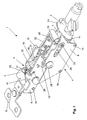
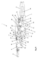
- Fig. 1 shows a perspective view of a closure 1 for locking a here not shown locking pin a Stoffhaltebügels a hood.
- the closure 1 has a closing unit 3 and a drive unit 4, each in one of a Housing basic body 5 and a housing cover 6 or from a first sheet metal part 7 and a housing formed second housing part 8 are arranged.
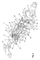
- Fig. 2 shows a further perspective view of the closure 1 in open form, i. without the housing cover 6 and the second sheet metal part eighth
- the hydraulic cylinder 39 is articulated with its free end via a hinge pin 33 a drive element 2 facing the end of a drive lever 12 is connected.
- a drive element 2 facing the end of a drive lever 12 is connected.
- to Guide the hydraulic cylinder 39 and to limit perpendicular to the hydraulic cylinder longitudinal axis directed movements serve two on both sides of the hinge pin 33rd between the ends and the side surfaces of the drive lever 12 arranged rollers 13, in correspondingly formed drive lever slots 34 in the first and second sheet-metal disc 7, 8 are arranged.
- the drive lever slots 34 are formed such that the hydraulic cylinder 39 and connected to the free end of the hydraulic cylinder 39 end of the drive lever 12 perform essentially a linear movement.
- the control lever 14 is in turn in the region of a second corner via a second Bearing pin 27 rotatably mounted on the housing of the drive unit 2. In the area of one third corner of the control lever 14 this is articulated via a third bearing pin 29 with the drive element 2 facing the end of two connecting levers 15a, 15b connected on the other hand hinged at the ends of two on both sides on a functional disc 17 arranged pins are attached, wherein a first pin 25 on the Housing cover 6 facing side protrudes through a slot 35 of the catch 16.
- the connecting lever 15a is arranged on the first pin 25, that the Rotary latch 16 between the connecting lever 15 a and the functional disk 17 is positioned is.
- the rotary latch 16 and the functional disk 17 are rotatable on a one common axis of rotation forming common first bearing pin 36 is arranged.
- the catch 16 is opposite the end of the mounted on the first pin 25 end of the Connecting lever 15 a supported by a first leg spring 21, with their free legs on the one hand on the first pin 25 and on the other hand on a second, rigidly connected to the rotary latch 16 connected second pin 24.
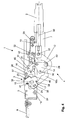
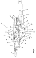
- This has the consequence that the rotary latch 16 against the functional disk 17 by the first leg spring 21st is supported, wherein the protruding through the slot 35 first pin 25 in through the closure pin of a fabric support bracket unloaded state of the rotary latch 16 on the an opening 41 for receiving the locking pin facing away from the end of the slot 35 is present (see Fig. 8).
- the functional disk 17 is in turn connected to a housing body 5 on the one hand on the other hand, attached to the functional disk 17 tension spring 23 in the direction of the position the functional disk 17 in the open position of the shutter 1, i. against the Direction of rotation of the functional disk 17 and the rotary latch 16 when closing the shutter 1, preloaded.
- the catch 16 has in its the opening 41 for receiving the not shown here Locking pin opposite portion two offset from each other Resting marks 37, 38 which engage with a locking projection 40 of a pawl 18 can be brought.
- the pawl 18 is adjacent to the functional disk 17 hinged on a parallel arranged to the first bearing pin 36 arranged bearing pin 26, wherein on the one hand on the housing cover 6 and on the other hand on the pawl 18 adjacent second leg spring 22 the locking projection 40 in the direction of the rotary latch 16 and the functional disk 17 biased.
- a stop pin 31 serves to limit the pivoting movement the pawl 18 in the direction of the functional disk 17 and the rotary latch 16 by as a contact surface for a on the pawl 18, the locking projection 40 opposite Latch 45 is used.
- a limit switch 20 which in the in Fig. 6 illustrated closed state of the closure 1 is activated.
- the limit switch 20 is connected to a Endschalterisme 32, by means of clip elements, the an corresponding openings are adapted to the housing base body 5, on the closure 1 is attached.
- the closure 1 On the one hand, two laterally projecting from the housing base body 5 and the housing cover 6 Connecting flanges 10 on.
- the housing cover 6 at its the Drive element 2 opposite end connected to a fastener 9, which is designed to receive screws, bolts, rivets or the like.
- the rotary latch 16 has previously unlocked become. This is only by an externally generated, independent of the functional disk 17 Movement of the rotary latch 16 possible, in which this predetermined in the slot 35 Angle range relative to the functional disk 17 in the illustrated in Fig. 4 Position is pivoted, wherein the locking projection 40 of the locking surface 18 from the catch mark 37 swings out.
- Such a pivoting of the rotary latch 16 can only by the interaction with caused the closure pin of the Stoffhaltebügels, not shown here, in the closing movement of the top with the shutter 1 and thereby with the catch 16 of the closure 1 is engaged.
- the closing movement takes place by a in the direction directed to the drive element 2 movement of the hydraulic cylinder 39.
- the Drive lever 12 is linearly displaced in the direction of the drive element 2, whereby in turn, the control disc 14 via the fourth bearing pin 30, in the selected here Representation counterclockwise, pivoted about the second bearing pin 27 becomes.
- the functional disk 17 and the rotary latch 16 are in the closing movement through the Connecting levers 15a and 15b pivoted together about the first bearing pin 36, whereby the closure pin, not shown here, of the fabric support bracket further into the Lock 1 is pulled into it.
- the functional disk 17 covers the second catch mark of the catch during the entire closing movement 16. Consequently, the both on the functional disk 17 and on the rotary latch 16 fitting latching projection 40 of the latch 18 do not engage in the second latching mark 38.
- the closure 1 is thereby starting from the open position shown in Fig. 3 after passing through the unlocked position shown in Fig. 4 manually through the Collaboration with the locking pin moves in the position shown in Fig. 7.
- the unlocking of the rotary latch 16 takes place by the manual or automatic operation of the top, wherein the at the Stoffhaltebügel arranged closure pin during the closing process of the hood with the Opening 41 of the rotary latch 16 engages and the rotary latch 16 in the illustrated in Fig. 4 Position moves.
- a manual pivoting the second bearing pin 27 allows the pawl 18 with a corresponding Tool be levered out by completely locking the closure 1, so that the shutter 1 can also be manually opened again.
Landscapes
- Engineering & Computer Science (AREA)
- Mechanical Engineering (AREA)
- Lock And Its Accessories (AREA)
- Seal Device For Vehicle (AREA)
Abstract
Description
- Fig. 1
- eine perspektivische Ansicht eines Verschlusses für einen Verschlusszapfen eines Stoffhaltebügels;
- Fig. 2
- eine weitere perspektivische Ansicht des Verschlusses von Fig. 1 mit einem geöffnetem Gehäuse;
- Fig. 3
- eine Seitenansicht des Verschlusses von Fig. 1 in geöffneter Stellung;
- Fig. 4
- eine Seitenansicht des Verschlusses von Fig. 1 mit einer entriegelten Sperrklinke;
- Fig. 5
- eine Seitenansicht des Verschlusses von Fig. 1 während eines Schließvorgangs;
- Fig. 6
- eine Seitenansicht des Verschlusses von Fig. 1 in geschlossener Stellung;
- Fig. 7
- eine Seitenansicht des Verschlusses von Fig. 1 in einer verriegelten Stellung nach einer Notbetätigung und
- Fig. 8
- eine Draufsicht des Verschlusses von Fig. 1.
Claims (18)
- Verschluss für Verdecke, Klappen oder dergleichen an Fahrzeugen, insbesondere zur Arretierung und Verspannung eines Stoffhaltebügels eines verschwenkbaren Pkw-Verdecks, mitdadurch gekennzeichnet, dasseiner eine Drehfalle aufweisenden Schließeinheit zur Aufnahme und Arretierung eines Halteelements undeiner Antriebseinheit zum Verschwenken der Drehfalle zwischen einer geöffneten Stellung und einer geschlossenen Stellung des Verschlusses,die Antriebseinheit (4) in der geöffneten Stellung des Verschlusses (1) in Richtung auf die geschlossene Stellung des Verschlusses (1) vorgespannt ist, wobeidie Drehfalle (16) durch das Halteelement entriegelbar in der geöffneten Stellung des Verschlusses (1) arretiert ist.
- Verschluss nach Anspruch 1, dadurch gekennzeichnet, dass die Schließeinheit (3) eine Funktionsscheibe (17) aufweist, die derart ausgebildet und mit der Drehfalle (16) und einer Rastvorrichtung (18) zusammenwirkt, dass sie die Drehfalle (16) in der geöffnete Stellung des Verschlusses (1) in Zuziehrichtung arretiert und das Zusammenwirken mit dem Halteelement eine die Drehfalle (16) entriegelnde Relativbewegung der Drehfalle (16) gegenüber der Funktionsscheibe (17) bewirkt.
- Verschluss nach Anspruch 1 oder 2, dadurch gekennzeichnet, dass die Funktionsscheibe (17) und die Drehfalle (16) auf einer gemeinsamen Schwenkachse gelenkig an der Schließeinheit (3) angeordnet sind, wobei die Funktionsscheibe (17) über einen starr an dieser befestigten und in einem Langloch (35) der Drehfalle (16) verlaufenden ersten Zapfen (25) mit der Drehfalle (16) verbunden ist.
- Verschluss nach einem oder mehreren der vorgehenden Ansprüche, dadurch gekennzeichnet, dass die Antriebseinheit (4) ein Antriebselement, insbesondere einen einen Hydraulikzylinder (39) aufweisenden hydraulischen Antrieb (2) aufweist, wobei der Hydraulikzylinder (39) an seinem freien Ende derart mit der Schließeinheit (3), insbesondere mit der Funktionsscheibe (17) verbunden ist, dass ein Verfahren des Hydraulikzylinders (39) ein Verschwenken der Drehfalle (16) zwischen der geöffneten Stellung und der geschlossenen Stellung des Verschlusses (1) bewirkt.
- Verschluss nach einem oder mehreren der vorhergehenden Ansprüche, dadurch gekennzeichnet, dass die Rastvorrichtung durch eine Rastklinke (18) gebildet ist, die einen Rastvorsprung (40) aufweist und derart angeordnet ist, dass der Rastvorsprung (40) in der geöffneten Stellung des Verschlusses (1) mit einer entsprechend ausgebildeten ersten Rastmarke (37) an der Drehfalle (16) in Eingriff bringbar ist.
- Verschluss nach einem oder mehren der vorhergehenden Ansprüche, dadurch gekennzeichnet, dass die Rastklinke (18) in Richtung auf die Drehfalle (16) und die Funktionsscheibe (17) vorgespannt ist, wobei der Rastvorsprung (40) an der Umfangsfläche der Funktionsscheibe (17) und der Drehfalle (16) anliegt.
- Verschluss nach einem oder mehreren der vorgehenden Ansprüche, dadurch gekennzeichnet, dass die Drehfalle (16) zur Sicherung einer notverriegelten Stellung eine zweite Rastmarke (38) aufweist, die mit der Rastklinke (18) in Eingriff bringbar ist, wobei die Funktionsscheibe (17) derart ausgebildet und an der Drehfalle (16) angeordnet ist, dass die Funktionsscheibe (17) die zweite Rastmarke (38) bei der Anlage des ersten Zapfens (25) an dem der zweiten Rastmarke (38) zugewandten Ende des Langlochs (35) in der durch einen ersten Lagerbolzen (36) gebildeten Schwenkachsenrichtung im wesentlichen vollständig überdeckt.
- Verschluss nach einem oder mehreren der vorgehenden Ansprüche, dadurch gekennzeichnet, dass ein Federelement, insbesondere eine Schenkelfeder (21) derart zwischen der Funktionsscheibe (17) und der Drehfalle (16) angeordnet ist, dass der erste Zapfen (25) der Funktionsscheibe (17) in Richtung auf das der zweiten Rastmarke (38) zugewandte Ende des Langlochs (35) vorgespannt ist.
- Verschluss nach einem oder mehreren der vorgehenden Ansprüche, dadurch gekennzeichnet, dass die Antriebseinheit (4) einen einerseits an dem freien Ende des Hydraulikzylinders (39) und andererseits an einem Steuerungshebel (14) schwenkbar gelagerten Antriebshebel (12) aufweist, wobei an dem um eine am Verschluss (1) ortsfeste Drehachse gelagerten Steuerungshebel (14) zusätzlich ein erstes Ende eines Verbindungshebels (15a) schwenkbar gelagert ist und ein dem ersten Ende gegenüberliegendes zweites Ende des Verbindungshebels (15a) mit der Schließeinheit (3), insbesondere der Funktionsscheibe (17), verbunden ist.
- Verschluss nach einem oder mehreren der vorgehenden Ansprüche, dadurch gekennzeichnet, dass das zweite Ende des Verbindungshebels (15a) gelenkig mit dem durch das Langloch (35) der Drehfalle (16) hindurchragenden Ende des ersten Zapfens (25) verbunden ist.
- Verschluss nach einem oder mehreren der vorgehenden Ansprüche, dadurch gekennzeichnet, dass ein zweiter, parallel zum Verbindungshebel (15a) angeordneter Verbindungshebel (15b) einerseits auf der Lagerachse des ersten Endes des Verbindungshebels (15a) gelenkig an dem Steuerungshebel (14) und andererseits gelenkig auf dem der Drehfalle (16) gegenüberliegenden Seite der Funktionsscheibe (17) befestigt ist.
- Verschluss nach einem oder mehreren der vorgehenden Ansprüche, dadurch gekennzeichnet, dass der Steuerungshebel (14) drehfest mit einem die ortsfeste Drehachse bildenden zweiten Lagerbolzen (27) verbunden ist und dass mindestens ein freies Ende des zweiten Lagerbolzen (27) zum Anschluss an ein manuelles Betätigungswerkzeug ausgebildet ist.
- Verschluss nach einem oder mehreren der vorgehenden Ansprüche, dadurch gekennzeichnet, dass der Verbindungshebel (15a) und der Antriebshebel (12) derart an dem Steuerungshebel (14) gelagert sind, dass die geschlossene Stellung des Verschlusses (1) durch eine Übertotpunktlagerung gesichert ist.
- Verschluss nach einem oder mehreren der vorgehenden Ansprüche, dadurch gekennzeichnet, dass zur Führung des mit dem freien Ende des Hydraulikzylinders (39) verbundenen Endes des Antriebshebels (12) auf den Enden des Gelenkstifts (33) Rollen (13) angeordnet sind, die in entsprechend ausgebildeten Antriebshebel-Langlöchern (34) in einem aus einem ersten und einem zweiten Blechteil (7, 8) gebildeten Gehäuse gelagert sind.
- Verschluss nach einem oder mehreren der vorgehenden Ansprüche, dadurch gekennzeichnet, dass der Antriebshebel (12) zur Bildung einer die geöffnete Stellung bestimmenden Endlage eine korrespondierend zum dritten Lagerbolzen (29) als Vertiefung ausgebildete Anlagefläche (43) aufweist.
- Verschluss nach einem oder mehreren der vorgehenden Ansprüche, dadurch gekennzeichnet, dass der Verbindungshebel (15a) zur Bildung einer die geschlossene Stellung bestimmenden Endlage eine korrespondierend zum zweiten Lagerbolzen (27) als Vertiefung ausgebildete Anlagefläche aufweist.
- Verschluss nach einem oder mehreren der vorgehenden Ansprüche, dadurch gekennzeichnet, dass ein Endschalter (20) vorgesehen ist, der die Endstellung des Hydraulikzylinders (39) in der geschlossene Stellung anzeigt.
- Verschluss nach einem oder mehreren der vorgehenden Ansprüche, dadurch gekennzeichnet, dass ein einerseits an einem Gehäusegrundkörper (5) der Schließeinheit (3) und andererseits an der Funktionsscheibe (17) angeordnetes Federelement, insbesondere eine Zugfeder (23) die Funktionsscheibe (17) in Richtung auf die Öffnungslage vorspannt.
Applications Claiming Priority (2)
| Application Number | Priority Date | Filing Date | Title |
|---|---|---|---|
| DE102004005644 | 2004-02-04 | ||
| DE200410005644 DE102004005644A1 (de) | 2004-02-04 | 2004-02-04 | Verschluss für Verdecke, insbesondere für einen Stoffhaltebügel eines Verdecks |
Publications (3)
| Publication Number | Publication Date |
|---|---|
| EP1561622A2 true EP1561622A2 (de) | 2005-08-10 |
| EP1561622A3 EP1561622A3 (de) | 2006-08-02 |
| EP1561622B1 EP1561622B1 (de) | 2008-05-14 |
Family
ID=34673168
Family Applications (1)
| Application Number | Title | Priority Date | Filing Date |
|---|---|---|---|
| EP20050001381 Expired - Lifetime EP1561622B1 (de) | 2004-02-04 | 2005-01-25 | Verschluss für Verdecke, insbesondere für einen Stoffhaltebügel eines Verdecks |
Country Status (3)
| Country | Link |
|---|---|
| EP (1) | EP1561622B1 (de) |
| DE (2) | DE102004005644A1 (de) |
| ES (1) | ES2307080T3 (de) |
Families Citing this family (1)
| Publication number | Priority date | Publication date | Assignee | Title |
|---|---|---|---|---|
| DE102007021083A1 (de) * | 2007-05-03 | 2008-11-06 | Webasto Ag | Verriegelungsvorrichtung für eine Dachabdeckung bei einem Fahrzeug |
Family Cites Families (5)
| Publication number | Priority date | Publication date | Assignee | Title |
|---|---|---|---|---|
| DE4111646C2 (de) * | 1991-04-10 | 1994-12-08 | Bayerische Motoren Werke Ag | Verriegelungseinrichtung, insbesondere für ein Cabrio-Faltverdeck |
| AT406661B (de) * | 1999-02-26 | 2000-07-25 | Pollmann Uhr & App Ernst | Verschlussvorrichtung, insbesondere für ein cabriolet-verdeck |
| DE19927236C1 (de) * | 1999-06-15 | 2000-10-12 | Webasto Vehicle Sys Int Gmbh | Verschlußvorrichtung |
| DE19944615C2 (de) * | 1999-09-17 | 2001-12-06 | Edscha Cabrio Verdecksys Gmbh | Schloß für ein verschwenkbares Kraftfahrzeugverdeck |
| DE10000002C2 (de) * | 2000-01-01 | 2002-06-27 | Webasto Vehicle Sys Int Gmbh | Verriegelungsvorrichtung für ein Klappverdeck |
-
2004
- 2004-02-04 DE DE200410005644 patent/DE102004005644A1/de not_active Ceased
-
2005
- 2005-01-25 EP EP20050001381 patent/EP1561622B1/de not_active Expired - Lifetime
- 2005-01-25 DE DE200550004069 patent/DE502005004069D1/de not_active Expired - Lifetime
- 2005-01-25 ES ES05001381T patent/ES2307080T3/es not_active Expired - Lifetime
Non-Patent Citations (1)
| Title |
|---|
| None |
Also Published As
| Publication number | Publication date |
|---|---|
| ES2307080T3 (es) | 2008-11-16 |
| DE502005004069D1 (de) | 2008-06-26 |
| EP1561622A3 (de) | 2006-08-02 |
| DE102004005644A1 (de) | 2005-09-08 |
| EP1561622B1 (de) | 2008-05-14 |
Similar Documents
| Publication | Publication Date | Title |
|---|---|---|
| EP1721768B1 (de) | Schiebetüre für ein Kraftfahrzeug | |
| DE102006032033B4 (de) | Drehfallenverschluss | |
| DE19841670A1 (de) | Schließeinrichtung | |
| EP3899179B1 (de) | Aufstellvorrichtung für ein kraftfahrzeugtürelement | |
| EP3734003B1 (de) | Türgriffanordnung | |
| DE4111646A1 (de) | Verriegelungseinrichtung, insbesondere fuer ein cabrio-faltverdeck | |
| DE19616655A1 (de) | Vorrichtung zum Öffnen und Schließen einer Tür oder Klappe | |
| DE102013008415A1 (de) | Kraftfahrzeugschloss | |
| EP2010739A2 (de) | Kraftfahrzeugtürverschluss | |
| EP1920962A2 (de) | Verdeck für ein Kraftfahrzeug, insbesondere Cabriolet-Fahrzeug, mit einem faltbaren Dach | |
| EP1561622B1 (de) | Verschluss für Verdecke, insbesondere für einen Stoffhaltebügel eines Verdecks | |
| DE10352488B3 (de) | Verschluß für Verdecke, Klappen oder dergleichen an Fahrzeugen | |
| EP0509137A1 (de) | Sattelkupplungseinrichtung Stichwort: Einhandbetätigungsgriff | |
| WO2024193865A1 (de) | Verriegelungseinrichtung für eine heckklappe eines kraftfahrzeugs | |
| DE102006057509B4 (de) | Aufstelldach für ein Fahrzeug, insbesondere für ein Campingfahrzeug | |
| DE102022107452A1 (de) | Kraftfahrzeugschloss | |
| DE102009050549B4 (de) | Betätigungsvorrichtung zum Öffnen und Schließen eines Fensters, einer Klappe oder dergleichen | |
| EP4174266A1 (de) | Flügelanordnung | |
| EP3385483B1 (de) | Schlossanordnung für ein fahrzeug | |
| DE19943315B4 (de) | Vorrichtung zum lösbaren Festsetzen eines beweglichen Fahrzeugteils an einem stationären Fahrzeugteil | |
| AT406661B (de) | Verschlussvorrichtung, insbesondere für ein cabriolet-verdeck | |
| DE69805371T2 (de) | Kraftfahrzeug-Türschloss | |
| EP4585435A1 (de) | Aufstelldachverriegelung | |
| DE10352489B3 (de) | Kraftunterstützter Verschluß für Verdecke, Klappen oder dergleichen an Fahrzeugen | |
| WO2024067917A1 (de) | Schlossbaugruppe |
Legal Events
| Date | Code | Title | Description |
|---|---|---|---|
| PUAI | Public reference made under article 153(3) epc to a published international application that has entered the european phase |
Free format text: ORIGINAL CODE: 0009012 |
|
| AK | Designated contracting states |
Kind code of ref document: A2 Designated state(s): AT BE BG CH CY CZ DE DK EE ES FI FR GB GR HU IE IS IT LI LT LU MC NL PL PT RO SE SI SK TR |
|
| AX | Request for extension of the european patent |
Extension state: AL BA HR LV MK YU |
|
| PUAL | Search report despatched |
Free format text: ORIGINAL CODE: 0009013 |
|
| AK | Designated contracting states |
Kind code of ref document: A3 Designated state(s): AT BE BG CH CY CZ DE DK EE ES FI FR GB GR HU IE IS IT LI LT LU MC NL PL PT RO SE SI SK TR |
|
| AX | Request for extension of the european patent |
Extension state: AL BA HR LV MK YU |
|
| 17P | Request for examination filed |
Effective date: 20070201 |
|
| AKX | Designation fees paid |
Designated state(s): DE ES FR GB IT |
|
| 17Q | First examination report despatched |
Effective date: 20070427 |
|
| GRAP | Despatch of communication of intention to grant a patent |
Free format text: ORIGINAL CODE: EPIDOSNIGR1 |
|
| GRAS | Grant fee paid |
Free format text: ORIGINAL CODE: EPIDOSNIGR3 |
|
| GRAA | (expected) grant |
Free format text: ORIGINAL CODE: 0009210 |
|
| AK | Designated contracting states |
Kind code of ref document: B1 Designated state(s): DE ES FR GB IT |
|
| REG | Reference to a national code |
Ref country code: GB Ref legal event code: FG4D Free format text: NOT ENGLISH |
|
| REF | Corresponds to: |
Ref document number: 502005004069 Country of ref document: DE Date of ref document: 20080626 Kind code of ref document: P |
|
| REG | Reference to a national code |
Ref country code: ES Ref legal event code: FG2A Ref document number: 2307080 Country of ref document: ES Kind code of ref document: T3 |
|
| RAP2 | Party data changed (patent owner data changed or rights of a patent transferred) |
Owner name: ISE AUTOMOTIVE GMBH |
|
| PLBE | No opposition filed within time limit |
Free format text: ORIGINAL CODE: 0009261 |
|
| STAA | Information on the status of an ep patent application or granted ep patent |
Free format text: STATUS: NO OPPOSITION FILED WITHIN TIME LIMIT |
|
| 26N | No opposition filed |
Effective date: 20090217 |
|
| PGFP | Annual fee paid to national office [announced via postgrant information from national office to epo] |
Ref country code: IT Payment date: 20090126 Year of fee payment: 5 |
|
| GBPC | Gb: european patent ceased through non-payment of renewal fee |
Effective date: 20090125 |
|
| PGFP | Annual fee paid to national office [announced via postgrant information from national office to epo] |
Ref country code: FR Payment date: 20090120 Year of fee payment: 5 |
|
| PG25 | Lapsed in a contracting state [announced via postgrant information from national office to epo] |
Ref country code: GB Free format text: LAPSE BECAUSE OF NON-PAYMENT OF DUE FEES Effective date: 20090125 |
|
| REG | Reference to a national code |
Ref country code: ES Ref legal event code: FD2A Effective date: 20090126 |
|
| PG25 | Lapsed in a contracting state [announced via postgrant information from national office to epo] |
Ref country code: ES Free format text: LAPSE BECAUSE OF NON-PAYMENT OF DUE FEES Effective date: 20090126 |
|
| REG | Reference to a national code |
Ref country code: FR Ref legal event code: ST Effective date: 20100930 |
|
| PG25 | Lapsed in a contracting state [announced via postgrant information from national office to epo] |
Ref country code: FR Free format text: LAPSE BECAUSE OF NON-PAYMENT OF DUE FEES Effective date: 20100201 |
|
| PG25 | Lapsed in a contracting state [announced via postgrant information from national office to epo] |
Ref country code: IT Free format text: LAPSE BECAUSE OF NON-PAYMENT OF DUE FEES Effective date: 20100125 |
|
| PGFP | Annual fee paid to national office [announced via postgrant information from national office to epo] |
Ref country code: DE Payment date: 20110126 Year of fee payment: 7 |
|
| PG25 | Lapsed in a contracting state [announced via postgrant information from national office to epo] |
Ref country code: DE Free format text: LAPSE BECAUSE OF NON-PAYMENT OF DUE FEES Effective date: 20120801 |
|
| REG | Reference to a national code |
Ref country code: DE Ref legal event code: R119 Ref document number: 502005004069 Country of ref document: DE Effective date: 20120801 |
|
| REG | Reference to a national code |
Ref country code: DE Ref legal event code: R082 Ref document number: 502005004069 Country of ref document: DE Representative=s name: KALKOFF & PARTNER PATENTANWAELTE, DE |
|
| REG | Reference to a national code |
Ref country code: DE Ref legal event code: R081 Ref document number: 502005004069 Country of ref document: DE Owner name: METALSA AUTOMOTIVE GMBH, DE Free format text: FORMER OWNER: ISE AUTOMOTIVE GMBH, 51702 BERGNEUSTADT, DE Effective date: 20130812 Ref country code: DE Ref legal event code: R082 Ref document number: 502005004069 Country of ref document: DE Representative=s name: KALKOFF & PARTNER PATENTANWAELTE, DE Effective date: 20130812 |