EP1561012B1 - Drehaktor-vorrichtung zur hubsteuerung von gaswechselventilen im zylinderkopf einer brennkraftmaschine - Google Patents
Drehaktor-vorrichtung zur hubsteuerung von gaswechselventilen im zylinderkopf einer brennkraftmaschine Download PDFInfo
- Publication number
- EP1561012B1 EP1561012B1 EP03795783A EP03795783A EP1561012B1 EP 1561012 B1 EP1561012 B1 EP 1561012B1 EP 03795783 A EP03795783 A EP 03795783A EP 03795783 A EP03795783 A EP 03795783A EP 1561012 B1 EP1561012 B1 EP 1561012B1
- Authority
- EP
- European Patent Office
- Prior art keywords
- cylinder head
- rotary actuator
- gas exchange
- head according
- internal combustion
- Prior art date
- Legal status (The legal status is an assumption and is not a legal conclusion. Google has not performed a legal analysis and makes no representation as to the accuracy of the status listed.)
- Expired - Lifetime
Links
- 238000002485 combustion reaction Methods 0.000 title claims abstract description 17
- 230000005540 biological transmission Effects 0.000 abstract description 11
- 230000006978 adaptation Effects 0.000 description 2
- 230000000712 assembly Effects 0.000 description 1
- 238000000429 assembly Methods 0.000 description 1
- 230000007423 decrease Effects 0.000 description 1
- 238000006073 displacement reaction Methods 0.000 description 1
- 238000005553 drilling Methods 0.000 description 1
- 239000000446 fuel Substances 0.000 description 1
- 238000003780 insertion Methods 0.000 description 1
- 230000037431 insertion Effects 0.000 description 1
- 230000003993 interaction Effects 0.000 description 1
- 238000004519 manufacturing process Methods 0.000 description 1
- 238000012856 packing Methods 0.000 description 1
Images

Classifications
-
- F—MECHANICAL ENGINEERING; LIGHTING; HEATING; WEAPONS; BLASTING
- F01—MACHINES OR ENGINES IN GENERAL; ENGINE PLANTS IN GENERAL; STEAM ENGINES
- F01L—CYCLICALLY OPERATING VALVES FOR MACHINES OR ENGINES
- F01L1/00—Valve-gear or valve arrangements, e.g. lift-valve gear
- F01L1/02—Valve drive
- F01L1/04—Valve drive by means of cams, camshafts, cam discs, eccentrics or the like
- F01L1/08—Shape of cams
-
- F—MECHANICAL ENGINEERING; LIGHTING; HEATING; WEAPONS; BLASTING
- F01—MACHINES OR ENGINES IN GENERAL; ENGINE PLANTS IN GENERAL; STEAM ENGINES
- F01L—CYCLICALLY OPERATING VALVES FOR MACHINES OR ENGINES
- F01L9/00—Valve-gear or valve arrangements actuated non-mechanically
- F01L9/20—Valve-gear or valve arrangements actuated non-mechanically by electric means
-
- F—MECHANICAL ENGINEERING; LIGHTING; HEATING; WEAPONS; BLASTING
- F01—MACHINES OR ENGINES IN GENERAL; ENGINE PLANTS IN GENERAL; STEAM ENGINES
- F01L—CYCLICALLY OPERATING VALVES FOR MACHINES OR ENGINES
- F01L2305/00—Valve arrangements comprising rollers
-
- F—MECHANICAL ENGINEERING; LIGHTING; HEATING; WEAPONS; BLASTING
- F01—MACHINES OR ENGINES IN GENERAL; ENGINE PLANTS IN GENERAL; STEAM ENGINES
- F01L—CYCLICALLY OPERATING VALVES FOR MACHINES OR ENGINES
- F01L9/00—Valve-gear or valve arrangements actuated non-mechanically
- F01L9/20—Valve-gear or valve arrangements actuated non-mechanically by electric means
- F01L9/22—Valve-gear or valve arrangements actuated non-mechanically by electric means actuated by rotary motors
Definitions
- the invention relates to a rotary actuator device for stroke control of at least two identical gas exchange valves in a cylinder head of an internal combustion engine according to the features in the preamble of patent claim 1.
- a valve train for an internal combustion engine which is designed as a spring-mass vibration system. It consists essentially of a swivel motor with a longitudinally extending in the cylinder head shaft, and a lever-like exciter device for each gas exchange valve.
- the exciter devices can be coupled to the shaft in accordance with the operating state of the internal combustion engine.
- the swivel motor only performs a pivoting movement in the sense of a stroke of the gas exchange valves.
- the shaft and the exciter devices which can be coupled thereto are virtually a camshaft with releasable cams. At the end of each cam, at the point of contact with the gas exchange valve, a roller is arranged to minimize friction.
- the valve train has two mutually point mirrored swivel motors, each with associated camshaft for all the same gas exchange valves.
- Object of the present invention is therefore to reduce the moving masses in a generic valve train.
- the moving masses are reduced in the valve train.
- the reduction in mass also reduces the resulting moments and thus the mechanical load on the entire valve train, as a result of which higher rotational speeds are possible.
- the internal friction of the valve train is substantially reduced, whereby the fuel consumption of the internal combustion engine decreases.
- the embodiment according to the claims 5 to 7 serves to reduce friction in the valve train with simultaneous backlash of the valve train components.
- the support of the power transmission element, on the one hand on a hydraulic valve clearance compensation element and on the other hand on a gas exchange valve reduces the moving masses, since in this arrangement, the hydraulic valve clearance compensation element can be arranged in the cylinder head, whereby at the same time a safe and simple oil supply is ensured,
- the cup in the embodiment according to the invention is completely eliminated, whereby this mass is eliminated from the moving valve train.
- the axes of the spark plug holes in the extension region of a device can be entangled against each other in order to maintain good insertion and removal conditions of the ignition device, such as. a spark plug to obtain the smallest possible compact unit for the rotary actuator device.
- the size of a device is again significantly reduced by this measure in the modular structure.
- Fig. 1 shows a schematic plan view of two inlet and outlet side on a cylinder head 4, an internal combustion engine, not shown, built rotary actuator devices 1, 1a, for the stroke control of four equivalent gas exchange valves 2, 2 ', 3, 3'.
- the structure consists essentially of the first rotary actuator device 1 and the second, for the first parallel shifted, rotary actuator device 1a.
- the first bore 10 and the second bore 10 'are each arranged centrally to a cylinder, not shown.
- the first bore 10 and the second bore 10 ' serve to receive an ignition device, not shown, for each cylinder.
- the rotary actuator devices 1, 1a are identical and differ only by the location of the obstruction.
- the rotary actuator device 1 is provided for an intake side, the rotary actuator device 1 a for an exhaust side of the internal combustion engine. In the following, only the rotary actuator device 1 will be explained in more detail, since all information can be transferred to the second rotary actuator device 1a.
- the rotary actuator device 1 essentially has a first and a second, point-mirrored, half rotary actuator device 14, 14 'for the stroke control of two identical gas exchange valves.
- the first half Drehaktor device 14 consists of a first pivot motor 5 with a stationary first shaft 6, to which two first actuating elements 7, 7a are arranged stationary.
- the first actuating elements 7, 7a here cams, interact with a respective first force transmission element 8, 8a.
- the power transmission elements 8, 8a are supported on one side each on a first clearance compensation element 9, 9a and on the opposite side in each case on a first gas exchange valve 2, 2 'from.
- This consists of a second pivot motor 5 ', with a stationary second shaft 6'.
- two further second actuating elements 7', 7a ' are arranged stationary. These are in interaction with two second power transmission elements 8 ', 8a', which in turn on the one hand to two second clearance compensation elements 9, 9a 'and on the other hand on two second gas exchange valves 3, 3' are supported.
- the rotary actuator device 1, consisting of the first and the second half rotary actuator device 14, 14 ' is provided for two cylinders of the internal combustion engine.
- Each half rotary actuator device 14, 14 ' actuates two identical gas exchange valves, here the inlet gas exchange valves for two cylinders of the internal combustion engine.
- a half Drehaktor device 14, 14 ' may be provided only for a single gas exchange valve. Also, the use of a half Drehaktor device 14, 14 'for two cylinders, each with only one gas acting equivalent valve is possible.
- first gas exchange valves 2, 2 'and the second gas exchange valves 3, 3' on a line, whereby the first shaft 6 and the second shaft 6 'and the first and second half Drehaktor device 14, 14' in parallel aligned with each other.
- the gas exchange valves can also assume a different position, whereby slightly different geometric arrangements are conceivable.
- the first power transmission elements 8, 8a and the second power transmission elements 8 ', 8a' are rocker arms, however, it is also possible to use rocker arms or roller rocker arms.
- the first clearance compensation elements 9, 9a and the second clearance compensation elements 9 ', 9a' are hydraulic valve clearance compensation elements, which are preferably incorporated directly into the cylinder head 4. As a result, a simple hydraulic supply is possible. All features that are shown for the rotary actuator device 1, also apply to the second rotary actuator device 1a.
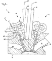
- Fig. 2 shows a schematic side view of the two rotary actuator device 1, 1a. Between the rotary actuator device 1 and the second rotary actuator device 1a is the first bore 10, for a not shown ignition device for the first cylinder. As under Fig. 1 already described the two rotary actuator devices 1 and 1 a are identical and point-only mirrored to each other, only the rotary actuator device 1 will be explained in more detail below again.
- an inlet gas exchange valve Above the valve stem end of the gas exchange valve 3, an inlet gas exchange valve, are juxtaposed the first half rotary anchor device 14, proximate to the first bore 10, and the second half rotary anchor device 14 ', further spaced from the first bore 10, on the cylinder head 4 attached.
- the actuating element 7a ' rests on the schematically illustrated first force transmission element 8a'.
- the power transmission element 8a ' is supported on the one hand on the clearance compensation element 9a' and on the other hand on the gas exchange valve 3, which is mounted in the cylinder head 4.
- the gas exchange valve 3 is shown in the open position and closes in a closed position an intake passage 15 in the cylinder head 4.
- the corresponding outlet gas exchange valve 2 is also shown in the open position and closes in the closed position an exhaust passage 16 in the cylinder head 4th
- the enclosure is preferably greater than 180 °, but always less than 360 °, whereby the mutually parallel shafts 6, 6 'structurally closer.
- This arrangement brings not only package advantages but also weight advantages.
- a further reduction in size is possible because the first bore 10 with the first axis 11 and the second bore 10 'with the second axis 11' are interlocked with each other, since in the embodiment according to the invention on the inlet side and on the outlet side a gas exchange valve and a clearance compensation element, respectively which have different space requirements.
Landscapes
- Engineering & Computer Science (AREA)
- Mechanical Engineering (AREA)
- General Engineering & Computer Science (AREA)
- Valve Device For Special Equipments (AREA)
- Valve-Gear Or Valve Arrangements (AREA)
Abstract
Description
- Die Erfindung betrifft eine Drehaktor-Vorrichtung zur Hubsteuerung von zumindest zwei gleichwirkenden Gaswechselventilen in einem Zylinderkopf einer Brennkraftmaschine gemäß den Merkmalen im Oberbegriff des Patentanspruchs 1.
- Sie geht von der deutschen Offenlegungsschrift
DE 198 25 964 A1 aus. In dieser wird ein Ventiltrieb für eine Brennkraftmaschine vorgeschlagen, der als Feder-Masse-Schwingungssystem ausgebildet ist. Er besteht im Wesentlichen aus einem Schwenkmotor mit einer längs im Zylinderkopf verlaufenden Welle, sowie einer hebelartigen Erregervorrichtung für jedes Gaswechselventil. Die Erregervorrichtungen sind entsprechend dem Betriebszustand der Brennkraftmaschine mit der Welle koppelbar. Der Schwenkmotor führt lediglich eine Schwenkbewegung im Sinne eines Hubes der Gaswechselventile aus. Bei der Welle und den daran koppelbaren Erregervorrichtungen handelt es sich quasi um eine Nockenwelle mit lösbaren Nocken. Am Ende eines jeden Nockens, am Berührpunkt zum Gaswechselventil, ist zur Reibungsminimierung eine Rolle angeordnet. Der Ventiltrieb weist für alle gleichwirkenden Gaswechselventile zwei zueinander punktgespiegelte Schwenkmotoren mit jeweils zugehöriger Nockenwelle auf. - Nachteilig an der beschriebenen Ausführung sind die großen Massenkräfte und die daraus resultierenden Momente, die die maximale Drehzahl der Brennkraftmaschine begrenzen.
- Aufgabe der vorliegenden Erfindung ist es daher, die bewegten Massen in einem gattungsgemäßen Ventiltrieb zu reduzieren.
- Diese Aufgabe wird durch die Merkmale im kennzeichnenden Teil des Patentanspruchs 1 gelöst.
In vorteilhafter Weise werden bei einer Ausgestaltung gemäß Patentanspruch 1 die bewegten Massen im Ventiltrieb reduziert. Durch die Massenreduzierung werden auch die hieraus resultierenden Momente und somit die mechanische Belastung des gesamten Ventiltriebs reduziert, wodurch höhere Drehzahlen möglich sind. Darüber hinaus wird die innere Reibung des Ventiltriebs wesentlich verringert, wodurch der Brennstoffverbrauch der Brennkraftmaschine sinkt. - Bei der Ausgestaltung gemäß Patentanspruch 2 entsteht eine kompakte kleine Antriebseinheit für zwei Zylinder. Diese Einheit kann in Verbindung mit Patentanspruch 9 zu einem modularen Konzept ausgebaut werden, so dass diese Einheit für jede Brennkraftmaschine einsetzbar ist, deren Zylinderzahl pro Zylinderreihe durch 2 teilbar ist. Eine selektive bauliche Anpassung an die jeweilige Brennkraftmaschine ist bei dieser modularen Bauweise nicht notwendig.
- Dieser modulare Aufbau wird in Patentanspruch 3 nochmals weiter ausgeführt. Bei dieser Ausgestaltungsvariante werden sowohl die Einlass- als auch die Auslassseite der einzelnen Zylinderpaare mit den gleichen modularen Baugruppen aufgebaut. Durch diese Maßnahme werden die Herstellkosten gesenkt.
- Besonders hervorzuheben ist bei Patentanspruch 4, dass bei einer beidseitigen Verbauung der Ventiltriebsvorrichtung, sowohl einlass- als auch auslassseitig, nur eine Parallelverschiebung der Drehaktor-Vorrichtung durchgeführt werden muss. Weitere Anpassungsarbeiten am Zylinderkopf sind nicht notwendig.
- Die Ausgestaltung gemäß der Patentansprüche 5 bis 7 dient der Verringerung von Reibung im Ventiltrieb bei gleichzeitiger Spielfreiheit der Ventiltriebsbauteile. Die Abstützung des Kraftübertragungselementes, einerseits auf einem hydraulischen Ventilspielausgleichselement und andererseits auf einem Gaswechselventil, reduziert die bewegten Massen, da bei dieser Anordnung das hydraulische Ventilspielausgleichselement im Zylinderkopf angeordnet werden kann, wodurch gleichzeitig eine sichere und einfache Ölversorgung gewährleistet ist, Gegenüber dem Stand der Technik, bei dem zwischen Drehmittel und Gaswechselventil ein Tassenstößel angeordnet ist, entfällt die Tasse bei der erfindungsgemäßen Ausgestaltung komplett, wodurch diese Masse aus dem bewegten Ventiltrieb entfällt.
- Um eine kompakte Bauweise zu erzielen, können gemäß Patentanspruch 8 die Achsen der Zündkerzenbohrungen im Erstreckungsbereich einer Vorrichtung gegeneinander verschränkt werden, um bei unverändert guten Ein- und Ausbaubedingungen der Zündeinrichtung, wie z.B. einer Zündkerze, die kleinstmögliche kompakte Baueinheit für die Drehaktor-Vorrichtung zu erhalten. Die Baugröße einer Vorrichtung wird durch diese Maßnahme beim modularen Aufbau nochmals wesentlich verringert.
- Eine weitere Reduzierung der Baugröße wird durch die Ausgestaltung gemäß Patentanspruch 10 erzielt, da bei einer derartigen Ausführung der den Rotor umgebenden Stator sich nicht über 360° radial am Umfang erstreckt. Durch diese Ausgestaltungsvariante wird die höchste Packungsdichte von Bauteilen erzielt.
- Im Folgenden ist die Erfindung anhand eines bevorzugten Ausführungsbeispieles in zwei Figuren näher erläutert.
- Fig. 1
- zeigt eine schematische Darstellung einer Aufsicht auf zwei einlasssowie auslassseitig auf einem Zylinderkopf einer Brennkraftmaschine verbauten Drehaktor-Vorrichtung,
- Fig. 2
- zeigt eine schematische Darstellung einer Seitenansicht von zwei einlass- sowie auslassseitig auf einem Zylinderkopf einer Brennkraftmaschine verbauten Drehaktor-Vorrichtung.
- Die Bezugszeichen in
Fig. 1 gelten auch für dieselben Bauteile inFig. 2 . -
Fig. 1 zeigt eine schematische Aufsicht auf zwei einlass- sowie auslassseitig auf einem Zylinderkopf 4, einer nicht dargestellten Brennkraftmaschine, verbauten Drehaktor-Vorrichtungen 1, 1a, zur Hubsteuerung von jeweils vier gleichwirkenden Gaswechselventilen 2, 2', 3, 3'. Der Aufbau besteht im Wesentlichen aus der ersten Drehaktor-Vorrichtung 1 sowie der zweiten, zur ersten parallel verschobenen, Drehaktor-Vorrichtung 1a. Zwischen den Drehaktor-Vorrichtungen 1 und 1a sind, in dem nicht näher dargestellten Zylinderkopf 4, eine erste Bohrung 10 und eine zweite Bohrung 10' angeordnet. Die erste Bohrung 10 und die zweite Bohrung 10' sind jeweils mittig zu einem nicht dargestellten Zylinder angeordnet. Die erste Bohrung 10 und die zweite Bohrung 10' dienen zur Aufnahme einer nicht dargestellten Zündvorrichtung für jeden Zylinder. Die Drehaktor-Vorrichtungen 1, 1a sind baugleich und unterscheiden sich nur durch den Ort der Verbauung. Die Drehaktor-Vorrichtung 1 ist für eine Einlassseite, die Drehaktor-Vorrichtung 1a für eine Auslassseite der Brennkraftmaschine vorgesehen. Im Weiteren wird nur die Drehaktor-Vorrichtung 1 näher erläutert, da alle Angaben auf die zweite Drehaktor-Vorrichtung 1a übertragbar sind. - Die Drehaktor-Vorrichtung 1 weist im Wesentlichen eine erste und eine zweite, zueinander punktgespiegelte, halbe Drehaktor-Vorrichtung 14, 14' zur Hubsteuerung von zwei gleichwirkenden Gaswechselventilen auf. Die erste halbe Drehaktor-Vorrichtung 14 besteht aus einem ersten Schwenkmotor 5 mit einer ortsfesten ersten Welle 6, an die zwei erste Betätigungselemente 7, 7a ortsfest angeordnet sind. Die ersten Betätigungselemente 7, 7a, hier Nocken, stehen in Wechselwirkung mit jeweils einem ersten Kraftübertragungselement 8, 8a. Die Kraftübertragungselemente 8, 8a stützen sich auf einer Seite jeweils auf einem ersten Spielausgleichselement 9, 9a und auf der gegenüberliegenden Seite jeweils auf einem ersten Gaswechselventil 2, 2' ab. Dasselbe gilt auch für die zweite halbe Drehaktor-Vorrichtung 14'. Diese besteht aus einem zweiten Schwenkmotor 5', mit einer ortsfesten zweiten Welle 6'. An die zweite Welle 6' sind zwei weitere zweite Betätigungselemente 7', 7a' ortsfest angeordnet. Diese stehen in Wechselwirkung mit zwei zweiten Kraftübertragungselementen 8', 8a', die wiederum einerseits auf zwei zweiten Spielausgleichselementen 9, 9a' und andererseits auf zwei zweiten Gaswechselventilen 3, 3' abgestützt sind.
- Im vorliegenden Ausführungsbeispiel ist die Drehaktor-Vorrichtung 1, bestehend aus der ersten und der zweiten halben Drehaktor-Vorrichtung 14, 14' für zwei Zylinder der Brennkraftmaschine vorgesehen. Jede halbe Drehaktor-Vorrichtung 14, 14' betätigt zwei gleichwirkende Gaswechselventile, hier die Einlass-Gaswechselventile für zwei Zylinder der Brennkraftmaschine. In einem weiteren Ausführungsbeispiel kann eine halbe Drehaktor-Vorrichtung 14, 14' auch nur für ein einzelnes Gaswechselventil vorgesehen sein. Auch die Verwendung einer halbe Drehaktor-Vorrichtung 14, 14' für zwei Zylinder, mit jeweils nur einem gleichwirkenden Gaswechselventil ist möglich.
- Im vorliegenden Ausführungsbeispiel liegen die ersten Gaswechselventile 2, 2' und die zweiten Gaswechselventile 3, 3' auf einer Linie, wodurch die erste Welle 6 und die zweite Welle 6' bzw. die erste und die zweite halbe Drehaktor-Vorrichtung 14, 14' parallel zueinander ausgerichtet sind. In weiteren Varianten können die Gaswechselventile jedoch auch eine andere Lage einnehmen, wodurch geringfügig andere geometrische Anordnungen denkbar sind.
- Die erste Welle 6 und die zweite Welle 6' sind Nockenwellen und die ersten Betätigungselemente 7, 7a und die zweiten Betätigungselemente 7', 7a' sind Nocken. Die ersten Kraftübertragungselemente 8, 8a und die zweiten Kraftübertragungselemente 8', 8a', sind Kipphebel, es können jedoch auch Schlepphebel oder Rollenschlepphebel eingesetzt werden. Die ersten Spielausgleichselemente 9, 9a und die zweiten Spielausgleichselemente 9', 9a' sind hydraulische Ventilspielausgleichselemente, die vorzugsweise direkt in den Zylinderkopf 4 eingearbeitet sind. Hierdurch ist eine einfache Hydraulikversorgung möglich. Alle Merkmale, die für die Drehaktor-Vorrichtung 1 dargestellt sind, gelten auch für die zweite Drehaktor-Vorrichtung 1a.
-
Fig. 2 zeigt eine schematische Seitenansicht der zwei Drehaktor-Vorrichtung 1, 1a. Zwischen der Drehaktor-Vorrichtung 1 und der zweiten Drehaktor-Vorrichtung 1a befindet sich die erste Bohrung 10, für eine nicht dargestellte Zündeinrichtung für den ersten Zylinder. Da wie unterFig. 1 bereits beschrieben die zwei Drehaktor-Vorrichtungen 1 und 1 a baugleich und nur zueinander punktgespiegelt sind, wird im Folgenden wiederum nur die Drehaktor-Vorrichtung 1 näher erläutert. - Oberhalb des Ventilschaftendes des Gaswechselventils 3, einem Einlass-Gaswechselventil, sind nebeneinander die erste halbe Drehanker-Vorrichtung 14, in der Nähe zur ersten Bohrung 10, und die zweite halbe Drehanker-Vorrichtung 14', von der ersten Bohrung 10 weiter beabstandet, am Zylinderkopf 4 befestigt. Am ersten Schwenkmotor 5 ist ein erster Stator 12 und ein erster Rotor 13 erkennbar, am zweiten Schwenkmotor 5' ist nur der zweite Stator 12' erkennbar, dessen zweiter Rotor 13' ist von der zentrisch angeordneten zweiten Welle 6', sowie dem zweiten Betätigungselement 7a' verdeckt. Das Betätigungselement 7a' liegt auf dem schematisch dargestellten ersten Kraftübertragungselement 8a' auf. Das Kraftübertragungselement 8a' ist einerseits auf dem Spielausgleichselement 9a' und andererseits auf dem Gaswechselventil 3 abgestützt, welches im Zylinderkopf 4 gelagert ist. Das Gaswechselventil 3 ist in Offenstellung dargestellt und verschließt in einer Schließstellung einen Einlasskanal 15 im Zylinderkopf 4. Das korrespondierende Auslass-Gaswechselventil 2 ist ebenfalls in Offenstellung dargestellt und verschließt in Schließstellung einen Auslasskanal 16 im Zylinderkopf 4.
- Um eine möglichst hohe Bauteildichte und somit eine kleine Baugröße zu erreichen, umschließen der erste Stator 12, bzw. der zweite Stator 12' den ersten Rotor 13 bzw. den zweiten Rotor 13' radial nicht am gesamten Umfang, sondern nur zu etwa 270°. Der Umschließungsgrad ist vorzugsweise größer als 180°, jedoch immer kleiner als 360°, wodurch die parallel zueinander verlaufenden Wellen 6, 6' baulich näher angeordnet sind. Diese Anordnung bringt neben Packagevorteilen auch Gewichtsvorteile. Eine weitere Baugrößenverkleinerung ist dadurch möglich, dass die erste Bohrung 10 mit der ersten Achse 11 und die zweite Bohrung 10' mit der zweiten Achse 11' zueinander verschränkt sind, da sich bei der erfindungsgemäßen Ausgestaltung einlassseitig und auslassseitig jeweils ein Gaswechselventil und ein Spielausgleichselement gegenüberliegen, die unterschiedliche Platzbedürfnisse haben.
-
- 1
- Drehaktor-Vorrichtung
- 1a
- Zweite Drehaktor-Vorrichtung
- 2, 2'
- Erstes Gaswechselventil
- 3, 3'
- Zweites Gaswechselventil
- 4
- Zylinderkopf
- 5
- Erster Schwenkmotor
- 5'
- Zweiter Schwenkmotor
- 6
- Erste Welle
- 6'
- Zweite Welle
- 7, 7a
- Erstes Betätigungselement
- 7', 7a'
- Zweites Betätigungselement
- 8, 8a
- Erstes Kraftübertragungselement
- 8', 8a'
- Zweites Kraftübertragungselement
- 9, 9a
- Erstes Spielausgleichselement
- 9', 9a'
- Zweites Spielausgleichselement
- 10
- Erste Bohrung
- 10'
- Zweite Bohrung
- 11
- Erste Achse
- 11'
- Zweite Achse
- 12
- Erster Stator
- 12'
- Zweiter Stator
- 13
- Erster Rotor
- 13'
- Zweiter Rotor
- 14
- Erste halbe Drehankervorrichtung
- 14'
- Zweite halbe Drehankervorrichtung
- 15
- Einlasskanal
- 16
- Auslasskanal
Claims (9)
- Zylinderkopf mit einer Drehaktorvorrichtung (1, 1a) zur Hubsteuerung von zumindest zwei gleichwirkenden Gaswechselventilen (2, 2", 3, 3') in einem Zylinderkopf (4) einer Brennkraftmaschine, bestehend aus einem ersten Schwenkmotor (5) mit einer ersten Welle (6), an die zumindest ein erstes Betätigungselement (7, 7ä) angeordnet ist und einem zweiten Schwenkmotor (5') mit einer zweiten Welle (6'), an die zumindest ein zweites Betätigungselement (7', 7a') angeordnet ist, wobei ein Betätigungselement (7, 7a, 7', 7a') für zumindest ein Gaswechselventil (2, 2', 3, 3') vorgesehen ist und der erste und der zweite Schwenkmotor (5, 5') punktgespiegelt angeordnet sind,
dadurch gekennzeichnet, dass zwischen dem Betätigungselement (7, 7a, 7', 7a') und dem Gaswechselventil (2, 2', 3, 3') ein Kraftübertragungselement (8, 8a, 8', 8a') angeordnet ist, wobei die Brennkraftmaschine zumindest einen ersten Zylinder mit einer ersten Zündeinrichtung in einer Bohrung im Zylinderkopf und einen zweiten Zylinder mit einer zweiten Zündvorrichtung in einer Bohrung im Zylinderkopf aufweist und wobei zumindest eine erste Achse (11) der ersten Bohrung (10) und eine zweite Achse (11') der zweiten Bohrung (10') zueinander verschränkt sind. - Zylinderkopf nach Patentanspruch 1, wobei die Brennkraftmaschine zumindest zwei Zylinder aufweist,
dadurch gekennzeichnet, dass zumindest eine Drehaktor-Vorrichtung (1) für zwei Zylinder vorgesehen ist. - Zylinderkopf nach Patentanspruch 1 oder 2, wobei jeder Zylinder eine Einlassseite und eine Auslassseite aufweist,
dadurch gekennzeichnet, dass der Einlassseite zumindest eine erste Drehaktor-Vorrichtung (1) und/oder der Auslassseite zumindest eine zweite Drehaktor-Vorrichtung (1a) zugeordnet ist. - Zylinderkopf nach Patentanspruch 3,
dadurch gekennzeichnet, dass die zweite Drehaktor-Vorrichtung (1a) zur ersten Drehaktor-Vorrichtung (1) parallel verschoben ist. - Zylinderkopf nach einem der zuvor genannten Patentansprüche,
dadurch gekennzeichnet, dass das Kraftübertragungselement (8, 8a, 8', 8a') ein Schlepphebel oder ein Rollenschlepphebel oder ein Kipphebel ist. - Zylinderkopf nach einem der zuvor genannten Patentansprüche,
dadurch gekennzeichnet, dass das Kraftübertragungselement (8, 8a, 8', 8a') einerseits auf einem Spielausgleichselement (9, 9', 9a, 9a') und andererseits auf einem Gaswechselventil (2, 2', 3, 3') abgestützt ist. - Zylinderkopf nach Patentanspruch 6,
dadurch gekennzeichnet, dass das Spielausgleichselement (9, 9', 9a, 9a') ein hydraulisches Ventilspielausgleichselement ist. - Zylinderkopf nach einem der zuvor genannten Patentansprüche,
dadurch gekennzeichnet, dass zumindest zwei Drehaktorvorrichtungen (1, 1 a) in Richtung einer Längsachse der Brennkraftmaschine aneinanderreihbar sind. - Zylinderkopf nach einem der zuvor genannten Patentansprüche, wobei der Schwenkmotor einen Stator und einen Rotor aufweist,
dadurch gekennzeichnet, dass sich der Stator (12) mindestens um 180° radial um den Rotor (13) erstreckt.
Applications Claiming Priority (3)
| Application Number | Priority Date | Filing Date | Title |
|---|---|---|---|
| DE10252997A DE10252997A1 (de) | 2002-11-14 | 2002-11-14 | Drehaktor-Vorrichtung zur Hubsteuerung von Gaswechselventilen im Zylinderkopf einer Brennkraftmaschine |
| DE10252997 | 2002-11-14 | ||
| PCT/EP2003/011408 WO2004044391A2 (de) | 2002-11-14 | 2003-10-15 | Drehaktor-vorrichtung zur hubsteuerung von gaswechselventilen im zylinderkopf einer brennkraftmaschine |
Publications (2)
| Publication Number | Publication Date |
|---|---|
| EP1561012A2 EP1561012A2 (de) | 2005-08-10 |
| EP1561012B1 true EP1561012B1 (de) | 2008-12-10 |
Family
ID=32185631
Family Applications (1)
| Application Number | Title | Priority Date | Filing Date |
|---|---|---|---|
| EP03795783A Expired - Lifetime EP1561012B1 (de) | 2002-11-14 | 2003-10-15 | Drehaktor-vorrichtung zur hubsteuerung von gaswechselventilen im zylinderkopf einer brennkraftmaschine |
Country Status (4)
| Country | Link |
|---|---|
| US (1) | US7007647B2 (de) |
| EP (1) | EP1561012B1 (de) |
| DE (2) | DE10252997A1 (de) |
| WO (1) | WO2004044391A2 (de) |
Families Citing this family (5)
| Publication number | Priority date | Publication date | Assignee | Title |
|---|---|---|---|---|
| DE102005033653B3 (de) * | 2005-07-19 | 2006-11-30 | Dr.Ing.H.C. F. Porsche Ag | Zwangsgesteuerter Ventiltrieb für eine Brennkraftmaschine |
| DE102006005943A1 (de) * | 2006-02-09 | 2007-08-23 | Bayerische Motoren Werke Ag | Verbrennungsmotor mit einem elektrischen Ventiltrieb |
| DE102006013100A1 (de) * | 2006-03-20 | 2007-09-27 | Lsp Innovative Automotive Systems Gmbh | Segmentmotor für Ventiltrieb |
| DE102006023652B4 (de) * | 2006-05-18 | 2008-10-30 | Esa Patentverwertungsagentur Sachsen-Anhalt Gmbh | Elektromotorische Einrichtung zur Betätigung von Gaswechselventilen |
| GB2447034A (en) * | 2007-02-28 | 2008-09-03 | Dakota Ltd Gibraltar | Camshaft Drive |
Family Cites Families (14)
| Publication number | Priority date | Publication date | Assignee | Title |
|---|---|---|---|---|
| GB1201214A (en) * | 1968-02-01 | 1970-08-05 | Ford Motor Co | Overhead camshaft internal combustion engine |
| DE3203791A1 (de) * | 1982-02-04 | 1983-08-11 | Volkswagenwerk Ag, 3180 Wolfsburg | Ventiltrieb, insbesondere fuer eine kraftfahrzeug-brennkraftmaschine |
| DE3210165A1 (de) * | 1982-03-19 | 1983-09-29 | Bayerische Motoren Werke AG, 8000 München | Ventiltrieb |
| DE3932293C1 (de) * | 1989-09-28 | 1991-01-24 | Mercedes-Benz Aktiengesellschaft, 7000 Stuttgart, De | |
| DE4212263A1 (de) * | 1992-04-11 | 1993-10-14 | Bayerische Motoren Werke Ag | Schaltvorrichtung für Hubventile einer Brennkraftmaschine |
| JPH0726911A (ja) * | 1993-05-13 | 1995-01-27 | Sumitomo Electric Ind Ltd | カムシャフト |
| DE4327068A1 (de) * | 1993-08-12 | 1995-02-16 | Bayerische Motoren Werke Ag | Ventiltrieb einer Brennkraftmaschine |
| CA2122188A1 (en) * | 1994-04-26 | 1995-10-27 | Peter Hinsperger | Fabric-vented greenhouse |
| JP3354314B2 (ja) | 1994-09-30 | 2002-12-09 | 本田技研工業株式会社 | エンジンのカム軸支持構造 |
| DE19825964A1 (de) * | 1998-06-10 | 1999-12-16 | Schaeffler Waelzlager Ohg | Ventiltrieb einer Brennkraftmaschine |
| EP0979928A1 (de) * | 1998-08-11 | 2000-02-16 | Wenko AG Burgdorf | Hubkolbenmotor mit Kipphebel-Ventilsteuerung |
| US6446589B1 (en) * | 2001-01-16 | 2002-09-10 | Chinh T. Nguyen | Cam actuated continuous simultaneously variable valve timing and lifting assembly |
| DE10140461A1 (de) * | 2001-08-17 | 2003-02-27 | Bayerische Motoren Werke Ag | Drehaktor-Vorrichtung zur Hubsteuerung eines Gaswechselventils im Zylinderkopf einer Brennkraftmaschine |
| US6722326B1 (en) * | 2002-10-14 | 2004-04-20 | Ford Global Technologies, Llc | Variable lift cylinder valve system for internal combustion engine |
-
2002
- 2002-11-14 DE DE10252997A patent/DE10252997A1/de not_active Withdrawn
-
2003
- 2003-10-15 DE DE50310913T patent/DE50310913D1/de not_active Expired - Lifetime
- 2003-10-15 EP EP03795783A patent/EP1561012B1/de not_active Expired - Lifetime
- 2003-10-15 WO PCT/EP2003/011408 patent/WO2004044391A2/de not_active Ceased
-
2005
- 2005-05-13 US US11/128,303 patent/US7007647B2/en not_active Expired - Fee Related
Also Published As
| Publication number | Publication date |
|---|---|
| US7007647B2 (en) | 2006-03-07 |
| DE50310913D1 (de) | 2009-01-22 |
| WO2004044391A3 (de) | 2004-06-17 |
| WO2004044391A2 (de) | 2004-05-27 |
| EP1561012A2 (de) | 2005-08-10 |
| US20050211211A1 (en) | 2005-09-29 |
| DE10252997A1 (de) | 2004-05-27 |
Similar Documents
| Publication | Publication Date | Title |
|---|---|---|
| DE19835921B4 (de) | Vorrichtung zur variablen Ventilbetätigung eines Zylinderventils | |
| DE3744343C2 (de) | ||
| EP1347154B1 (de) | Ventilsteuerung zur Einstellung des Hubes von Ventilen in einer Brennkraftmaschine | |
| DE19815112A1 (de) | Anordnung zur variablen Ventilzeitsteuerung und Ventilbetätigung | |
| EP2118454B1 (de) | Ventiltrieb eines hubkolben-verbrennungsmotors | |
| DE102006034951A1 (de) | Ventiltrieb für eine Brennkraftmaschine | |
| DE102011116130A1 (de) | Ventiltrieb für eine Brennkraftmaschine | |
| EP1561012B1 (de) | Drehaktor-vorrichtung zur hubsteuerung von gaswechselventilen im zylinderkopf einer brennkraftmaschine | |
| DE60305981T2 (de) | Ventilbetätigungsvorrichtung für variable ventilsteuerung für gaswechselventile einer brennkraftmaschine | |
| DE102016112449B4 (de) | Ventiltrieb für eine Brennkraftmaschine und Brennkraftmaschine | |
| DE69800537T2 (de) | Anordnung mit zwei obenliegenden Nockenwellen und Brennkraftmaschine mit dieser Anordnung | |
| DE10141012A1 (de) | Ventilbetätigungsvorrichtung für Brennkraftmaschinen | |
| DE4242634C2 (de) | Einrichtung zur stufenlosen Variierung von Ventilhub und Steuerzeiten der Einlaß- und der Auslaßventile einer Hubkolbenbrennkraftmaschine | |
| DE102006005333B4 (de) | Ventiltrieb für eine Brennkraftmaschine | |
| EP1608852B1 (de) | Vorrichtung zur variablen bet tigung der gaswechselventile v on verbrennungsmotoren und verfahren zum betreiben einer derartigen vorrichtung | |
| DE10312959A1 (de) | Vorrichtung zur variablen Betätigung der Gaswechselventile von Verbrennungsmotoren und Verfahren zum Betreiben einer derartigen Vorrichtung | |
| DE10306154A1 (de) | Ventiltrieb für eine Brennkraftmaschine | |
| DE10323665A1 (de) | Variable Ventilhubvorrichtung zur Hubverstellung der Gaswechselventile einer Verbrennungskraftmaschine | |
| DE10235401A1 (de) | Hubvariabler Ventiltrieb | |
| EP0990776B1 (de) | Brennkraftmaschine mit zwei in V-Form angeordneten Zylinderbänken | |
| DE10237104A1 (de) | Ventiltrieb für eine Hubkolben-Brennkraftmaschine | |
| DE10352677A1 (de) | Aktuatorik für Verbrennungsmotoren mit einer variablen Ventilsteuerung | |
| DE102014116191C5 (de) | Ventiltrieb zur Betätigung von Gaswechselventilen einer Brennkraftmaschine | |
| EP0663515B1 (de) | Vorrichtung zum Ventilspielausgleich | |
| AT399021B (de) | Ventilsteuerung für brennkraftmaschinen |
Legal Events
| Date | Code | Title | Description |
|---|---|---|---|
| PUAI | Public reference made under article 153(3) epc to a published international application that has entered the european phase |
Free format text: ORIGINAL CODE: 0009012 |
|
| 17P | Request for examination filed |
Effective date: 20050127 |
|
| AK | Designated contracting states |
Kind code of ref document: A2 Designated state(s): AT BE BG CH CY CZ DE DK EE ES FI FR GB GR HU IE IT LI LU MC NL PT RO SE SI SK TR |
|
| RBV | Designated contracting states (corrected) |
Designated state(s): DE FR GB IT |
|
| GRAP | Despatch of communication of intention to grant a patent |
Free format text: ORIGINAL CODE: EPIDOSNIGR1 |
|
| GRAS | Grant fee paid |
Free format text: ORIGINAL CODE: EPIDOSNIGR3 |
|
| GRAA | (expected) grant |
Free format text: ORIGINAL CODE: 0009210 |
|
| AK | Designated contracting states |
Kind code of ref document: B1 Designated state(s): DE FR GB IT |
|
| REG | Reference to a national code |
Ref country code: GB Ref legal event code: FG4D Free format text: NOT ENGLISH |
|
| REF | Corresponds to: |
Ref document number: 50310913 Country of ref document: DE Date of ref document: 20090122 Kind code of ref document: P |
|
| PLBE | No opposition filed within time limit |
Free format text: ORIGINAL CODE: 0009261 |
|
| STAA | Information on the status of an ep patent application or granted ep patent |
Free format text: STATUS: NO OPPOSITION FILED WITHIN TIME LIMIT |
|
| 26N | No opposition filed |
Effective date: 20090911 |
|
| PG25 | Lapsed in a contracting state [announced via postgrant information from national office to epo] |
Ref country code: GB Free format text: LAPSE BECAUSE OF NON-PAYMENT OF DUE FEES Effective date: 20091015 |
|
| PG25 | Lapsed in a contracting state [announced via postgrant information from national office to epo] |
Ref country code: IT Free format text: LAPSE BECAUSE OF FAILURE TO SUBMIT A TRANSLATION OF THE DESCRIPTION OR TO PAY THE FEE WITHIN THE PRESCRIBED TIME-LIMIT Effective date: 20081210 |
|
| REG | Reference to a national code |
Ref country code: FR Ref legal event code: PLFP Year of fee payment: 13 |
|
| PGFP | Annual fee paid to national office [announced via postgrant information from national office to epo] |
Ref country code: DE Payment date: 20151031 Year of fee payment: 13 |
|
| PGFP | Annual fee paid to national office [announced via postgrant information from national office to epo] |
Ref country code: FR Payment date: 20151029 Year of fee payment: 13 |
|
| REG | Reference to a national code |
Ref country code: DE Ref legal event code: R119 Ref document number: 50310913 Country of ref document: DE |
|
| REG | Reference to a national code |
Ref country code: FR Ref legal event code: ST Effective date: 20170630 |
|
| PG25 | Lapsed in a contracting state [announced via postgrant information from national office to epo] |
Ref country code: DE Free format text: LAPSE BECAUSE OF NON-PAYMENT OF DUE FEES Effective date: 20170503 Ref country code: FR Free format text: LAPSE BECAUSE OF NON-PAYMENT OF DUE FEES Effective date: 20161102 |