EP1560984B1 - Stützvorrichtung für schienen eines schotterlosen gleisoberbaus - Google Patents
Stützvorrichtung für schienen eines schotterlosen gleisoberbaus Download PDFInfo
- Publication number
- EP1560984B1 EP1560984B1 EP03775485A EP03775485A EP1560984B1 EP 1560984 B1 EP1560984 B1 EP 1560984B1 EP 03775485 A EP03775485 A EP 03775485A EP 03775485 A EP03775485 A EP 03775485A EP 1560984 B1 EP1560984 B1 EP 1560984B1
- Authority
- EP
- European Patent Office
- Prior art keywords
- rail support
- railway track
- track rail
- support according
- rigid shell
- Prior art date
- Legal status (The legal status is an assumption and is not a legal conclusion. Google has not performed a legal analysis and makes no representation as to the accuracy of the status listed.)
- Expired - Lifetime
Links
- 229910000831 Steel Inorganic materials 0.000 claims abstract description 6
- 230000003014 reinforcing effect Effects 0.000 claims abstract description 6
- 239000010959 steel Substances 0.000 claims abstract description 6
- 229920001971 elastomer Polymers 0.000 claims abstract description 5
- 239000000806 elastomer Substances 0.000 claims abstract description 5
- 239000002184 metal Substances 0.000 claims abstract description 5
- 239000000463 material Substances 0.000 claims description 12
- 230000006835 compression Effects 0.000 claims description 5
- 238000007906 compression Methods 0.000 claims description 5
- 238000005520 cutting process Methods 0.000 claims description 3
- 239000002991 molded plastic Substances 0.000 claims description 2
- 229920002994 synthetic fiber Polymers 0.000 claims description 2
- 229910000639 Spring steel Inorganic materials 0.000 abstract 1
- 230000037431 insertion Effects 0.000 abstract 1
- 238000003780 insertion Methods 0.000 abstract 1
- 238000004519 manufacturing process Methods 0.000 description 4
- 238000009826 distribution Methods 0.000 description 2
- 238000009434 installation Methods 0.000 description 2
- 238000005266 casting Methods 0.000 description 1
- 238000010276 construction Methods 0.000 description 1
- 230000002950 deficient Effects 0.000 description 1
- 238000001035 drying Methods 0.000 description 1
- 238000011065 in-situ storage Methods 0.000 description 1
- 230000008595 infiltration Effects 0.000 description 1
- 238000001764 infiltration Methods 0.000 description 1
- 238000002347 injection Methods 0.000 description 1
- 239000007924 injection Substances 0.000 description 1
- 239000004570 mortar (masonry) Substances 0.000 description 1
- 238000000465 moulding Methods 0.000 description 1
- 239000011347 resin Substances 0.000 description 1
- 229920005989 resin Polymers 0.000 description 1
- 238000007789 sealing Methods 0.000 description 1
- 238000000926 separation method Methods 0.000 description 1
- 239000000243 solution Substances 0.000 description 1
- 238000006467 substitution reaction Methods 0.000 description 1
- XLYOFNOQVPJJNP-UHFFFAOYSA-N water Substances O XLYOFNOQVPJJNP-UHFFFAOYSA-N 0.000 description 1
- 238000003466 welding Methods 0.000 description 1
Images
Classifications
-
- E—FIXED CONSTRUCTIONS
- E01—CONSTRUCTION OF ROADS, RAILWAYS, OR BRIDGES
- E01B—PERMANENT WAY; PERMANENT-WAY TOOLS; MACHINES FOR MAKING RAILWAYS OF ALL KINDS
- E01B3/00—Transverse or longitudinal sleepers; Other means resting directly on the ballastway for supporting rails
- E01B3/28—Transverse or longitudinal sleepers; Other means resting directly on the ballastway for supporting rails made from concrete or from natural or artificial stone
- E01B3/40—Slabs; Blocks; Pot sleepers; Fastening tie-rods to them
-
- E—FIXED CONSTRUCTIONS
- E01—CONSTRUCTION OF ROADS, RAILWAYS, OR BRIDGES
- E01B—PERMANENT WAY; PERMANENT-WAY TOOLS; MACHINES FOR MAKING RAILWAYS OF ALL KINDS
- E01B1/00—Ballastway; Other means for supporting the sleepers or the track; Drainage of the ballastway
- E01B1/002—Ballastless track, e.g. concrete slab trackway, or with asphalt layers
- E01B1/005—Ballastless track, e.g. concrete slab trackway, or with asphalt layers with sleeper shoes
Definitions
- the present invention relates to a railway rail support slab track, that is to say without ballast. Such channels are used in particular in tunnels.
- a railway rail support is composed of a concrete block or blochet whose upper part is provided with means for fixing the rail.
- the shape of the lower part of the concrete block is, in turn, designed to adapt to the shape of an elastomeric envelope also called slipper.
- an elastomeric sole whose surface is substantially equal to the surface of the lower face of the block.
- This sole has an elasticity adapted to the nature of the traffic on the line to mitigate the vibrations emitted during the passage of a train and give the track flexibility in compression in the vertical direction. Such flexibility can also be obtained by means of groove reliefs, present on the bottom of the envelope.
- the laying in way of this system is carried out in different successive phases: the first phase is the fixing phase of the rail on the support on the one hand and the embedding of the envelope on the support on the other hand.
- the second phase is the positioning phase of the assembly formed by the rail, the support and the envelope to obtain the desired track layout.
- the third phase is the sealing phase of the concreting track, which permanently freezes the position of the track.
- the external dimensions of the concrete blocks can vary substantially from one block to another, particularly because of the shrinkage phenomenon that occurs when the concrete dries and hardens. This variation is problematic when it is desired to replace a defective or damaged support, following a derailment, for example, with another support. Indeed, it is possible that in this case the dimensions of the new support do not allow to enter properly into the cavity left in the cavity of the slab by the old support.
- the second reason, of an economic nature, is that the concrete supports have a weight such that the transport over long distances presents a handicap in term of cost of transport; a palliative would be to manufacture the supports near the place of installation of the way but that supposes a transfer of know-how and material whose cost is not always compatible with the yard considered, in particular when it comes to the construction of metro lines, because of the size of the yard, or that of a railway line in a country under equipped.
- the present invention aims to remedy the shortcomings of the existing solutions mentioned above.
- a rail rail support for slab track comprising a block of molded material whose upper part is provided with rail fastening means, embedded in an envelope comprising a vertical wall and a bottom, said envelope being itself housed in a cavity of said slab, characterized in that said block is molded in a rigid shell forming a lost mold so that the assembly of said block and said rigid shell constitutes a blochet of which the shape and outer dimensions correspond and adapt to the shape and internal dimensions of said envelope, in that said envelope forms a liner and the lower face of the rattle rests on the bottom of said liner.
- the blocket thus formed can rest directly on the bottom of the liner possibly with the interposition of a relatively flexible sole, if necessary. This guarantees the possibility of replacement of the blochet by simple substitution.
- one or more reinforcing grids are secured to the rigid shell and embedded in the block of molded material. This makes it possible to avoid the separation of these last two elements in the event of a phenomenon of withdrawal of the molded material during drying.
- the railway rail support according to a preferred embodiment of the invention is such that the horizontal section of the outer contour of the rigid shell has a curvilinear shape, for example circular. In the latter case, it is advantageous to cut the shell in a circular section tube, metal, preferably steel.
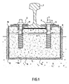
- the support as shown comprises a block of molded material 1, concrete in the example described, the upper part of which is capable of fastening means 2 of the rail 7.
- These fastening means comprise an external threaded bolt 3 for to be fixed by screwing into a female element, a kind of peg 4 with internal threading, a spring blade 5 of steel and an elastomer strip 6 having longitudinal grooves to allow flexibility in compression during the passage of the train.
- the lower part of the rail 7 is held between the upper part of the peg 4 and the elastomer strip 6 by clamping the male element 3 in the female element 4.
- the spring blade 5 is used to transmit the clamping force on the heel 13 of the rail 7, while distributing the force on a certain surface.
- This support is embedded in an envelope 8, itself housed in a cavity of the slab 9.
- the bottom 8a of the envelope 8 has radial grooves 14 intended to provide flexibility in compression to the envelope to attenuate the vibrations emitted when passing a train.
- the block of molded material 1 is surrounded by a rigid shell 10, a kind of lost mold in which the molding of said block took place. The whole forms a rattle that may need to be healed if the track deteriorates. The rattle rests on the bottom of the shoe.
- a reinforcing grid 11 secured to the rigid shell 8 is embedded in the block of molded material 1.
- the end of the rigid shell 10 has a chamfer 12 facilitating its embedding in the envelope 8.
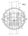
- the horizontal section of the outer contour of the rigid shell, shown on the figure 2 is circular and obtained by cutting to length of a metal tube, preferably steel.
- a non-circular curvilinear section could, however, be suitable.
- the upper end of said rigid shell 10 advantageously has two diametrically opposite notches allowing the passage of the rail 7.
- the shape and outer dimensions of the rigid shell 10 are adapted to the inner dimensions of the casing 8 and the lower face of the assembly consisting of the concrete block and the rigid shell rest on the bottom 8b of the envelope 8.
- the bottom 8b is provided with studs 20 integrally molded, which play the same role as the grooves 14.
- the number and dimensions of these studs can be adapted according to the elasticity that is desired to give the bottom of the liner, on which rests the assembly forming the blocket, constituted by the concrete block 1 and the rigid shell 10.
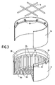
- the envelope itself is conventionally made of synthetic material, for example elastomer or the like, as in the case of the previous embodiment.
- the vertical wall 22 generally cylindrical, has vertical ribs 24 chamfered at their upper ends, which facilitates the introduction and sliding of the rigid shell 10.
- the edge of the envelope 8 slipper comprises a ring 26 shaped to receive a clamping collar 28.
- This ring is connected to the rest of the vertical wall by a thinned annular portion 30.
- the ring 26 is provided externally with segments 32 offset axially and circumferentially and defining between them the housing of the clamping collar 28. The latter makes it possible to seal between the cylindrical outer wall of the rigid shell 10 and the liner, preventing the infiltration of water between these two elements. If, following an incident, it is necessary to replace the rattle, simply remove the collar and extract said rattle vertically by sliding it in the boot.
- the rigid shell 8 is molded plastic.
- Clipping means 36 are integrally molded with the rigid shell 10 and projecting therein. The ends of a reinforcing grid 11 can engage in these clipping means, which allows an immediate installation of said grid (no welding is necessary as in the previous example) before pouring the concrete in said rigid shell forming a lost mold.
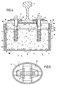
- shoe 8 represented at figure 3 can perfectly receive a rigid metal shell like that described with reference to figures 1 and 2 .
- the rigid shell 10 and the shoe 8 are generally cylindrical with a circular section.
- a non-circular curvilinear section was possible, preferably any parallelepiped shape, to ensure a better distribution of stresses on the envelope.
- the horizontal sections of the rigid shell 10 and the shoe 8 have an oval contour, the largest dimension of the support extending substantially perpendicularly to the rail. This advantageous form is illustrated on the figure 5 .
- the transverse dimension is significantly greater than its height.
- the transverse dimension will be at least about twice the height.
Landscapes
- Engineering & Computer Science (AREA)
- Architecture (AREA)
- Civil Engineering (AREA)
- Structural Engineering (AREA)
- Machines For Laying And Maintaining Railways (AREA)
- Railway Tracks (AREA)
- Train Traffic Observation, Control, And Security (AREA)
- Magnetic Heads (AREA)
- Buildings Adapted To Withstand Abnormal External Influences (AREA)
- Road Paving Structures (AREA)
- Forms Removed On Construction Sites Or Auxiliary Members Thereof (AREA)
- Non-Portable Lighting Devices Or Systems Thereof (AREA)
Claims (16)
- Eisenbahnschienenstützvorrichtung für feste Fahrbahn, umfassend einen Block aus gegossenem Material (1), dessen oberer Teil mit Mitteln zur Befestigung der Schiene (2) versehen ist und welcher in eine Hülle (8) umfassend einen vertikalen Rand und einen Boden eingefügt ist, wobei die Hülle (8) selbst in einem Hohlraum der Fahrbahn (9) angeordnet ist, dadurch gekennzeichnet, daß der Block in einer festen Schale (10), welche eine Einweggießform bildet, eingegossen ist, so daß die Anordnung aus dem Block und der festen Schale einen Schwellenblock ausbildet, dessen Form und äußere Abmessungen an die Form und die äußeren Abmessungen der Hülle (8) angepaßt und angeglichen sind, so daß die Hülle einen Bezug bildet und die untere Seite des Schwellenblocks auf dem Boden des Bezugs liegt.
- Eisenbahnschienenstützvorrichtung nach Anspruch 1, dadurch gekennzeichnet, daß ein oder mehrere Verstärkungsgitter (11) mit der festen Schale (10) verbunden und in den Block eingebettet sind.
- Eisenbahnschienenstützvorrichtung nach Anspruch 1 oder 2, dadurch gekennzeichnet, daß das Ende der festen Schale (10) eine ihre Einfügung in die Hülle (8) erleichternde Fase (12) besitzt.
- Eisenbahnschienenstützvorrichtung nach einem der Ansprüche 1 bis 3, dadurch gekennzeichnet, daß der horizontale Querschnitt des äußeren Randes der festen Schale (10) krummlinig ist.
- Eisenbahnschienenstützvorrichtung nach einem der Ansprüche 1 bis 4, dadurch gekennzeichnet, daß der horizontale Querschnitt des äußeren Randes der festen Schale (10) kreisförmig ist.
- Eisenbahnschienenstützvorrichtung nach einem der Ansprüche 1 bis 5, dadurch gekennzeichnet, daß die feste Schale (10) durch Längsschneiden eines metallischen Rohres, vorzugsweise aus Stahl, gebildet ist.
- Eisenbahnschienenstützvorrichtung nach einem der Ansprüche 1 bis 6, dadurch gekennzeichnet, daß das gegossene Material (1) Beton ist.
- Eisenbahnschienenstützvorrichtung nach einem der vorhergehenden Ansprüche, dadurch gekennzeichnet, daß nach bekannter Art die bezugsbildende Hülle (8) aus einem synthetischen Material, z.B. der elastomeren Sorte oder ähnlichem, besteht.
- Eisenbahnschienenstützvorrichtung nach einem der vorhergehenden Ansprüche, dadurch gekennzeichnet, daß der Boden (8a) des Bezugs, auf welchem die aus dem Block und der festen Schale gebildete Anordnung liegt, Rillen aufweist.
- Eisenbahnschienenstützvorrichtung nach einem der Ansprüche 1 bis 8, dadurch gekennzeichnet, daß der Boden (8b) des Bezugs, auf welchem die aus dem Block und der festen Schale gebildete Anordnung liegt, durch Gießen erhaltene Noppen (20) aufweist.
- Eisenbahnschienenstützvorrichtung nach einem der vorhergehenden Ansprüche, dadurch gekennzeichnet, daß die vertikale Wand des Bezugs vertikale Rippen (24) aufweist.
- Eisenbahnschienenstützvorrichtung nach einem der vorhergehenden Ansprüche, dadurch gekennzeichnet, daß der Rand des Bezugs einen Ring (26) aufweist, welcher zur Aufnahme einer Schelle (28) ausgebildet ist, wobei der Ring über einen dünneren ringförmigen Teil (30) mit der vertikalen Wand verbunden ist.
- Eisenbahnschienenstützvorrichtung nach einem der vorhergehenden Ansprüche, dadurch gekennzeichnet, daß die feste Schale (10) aus einem plastischen Gußstoff besteht.
- Eisenbahnschienenstützvorrichtung nach Anspruch 13, dadurch gekennzeichnet, daß Schnappverschlüsse (36) mit der festen Schale gegossen sind und zum inneren derselben hervorstehen, so daß die Endstücke eines Verstärkungsgitters (11) in den Schnappverschlüssen einrasten können.
- Eisenbahnschienenstützvorrichtung nach einem der vorhergehenden Ansprüche, dadurch gekennzeichnet, daß die horizontalen Querschnitte der festen Schale und des Bezugs eine ovale Kontur haben, wobei die größere Abmessung der Stützvorrichtung sich in eine zu den Schienen im wesentlichen senkrechte Richtung erstreckt. (Fig. 5).
- Eisenbahnschienenstützvorrichtung nach einem der vorhergehenden Ansprüche, dadurch gekennzeichnet, daß ihre Querabmessung mindestens etwa das doppelte ihrer Höhe ist, damit die Stützvorrichtung im wesentlichen unter Druckbeanspruchung arbeitet.
Applications Claiming Priority (3)
| Application Number | Priority Date | Filing Date | Title |
|---|---|---|---|
| FR0212804 | 2002-10-15 | ||
| FR0212804A FR2845700B1 (fr) | 2002-10-15 | 2002-10-15 | Support de rail pour voie sans ballast |
| PCT/FR2003/003032 WO2004035934A1 (fr) | 2002-10-15 | 2003-10-15 | Support de rail pour voie sans ballast |
Publications (2)
| Publication Number | Publication Date |
|---|---|
| EP1560984A1 EP1560984A1 (de) | 2005-08-10 |
| EP1560984B1 true EP1560984B1 (de) | 2009-09-16 |
Family
ID=32039745
Family Applications (1)
| Application Number | Title | Priority Date | Filing Date |
|---|---|---|---|
| EP03775485A Expired - Lifetime EP1560984B1 (de) | 2002-10-15 | 2003-10-15 | Stützvorrichtung für schienen eines schotterlosen gleisoberbaus |
Country Status (7)
| Country | Link |
|---|---|
| EP (1) | EP1560984B1 (de) |
| AT (1) | ATE443182T1 (de) |
| AU (1) | AU2003283511A1 (de) |
| DE (1) | DE60329315D1 (de) |
| ES (1) | ES2333713T3 (de) |
| FR (1) | FR2845700B1 (de) |
| WO (1) | WO2004035934A1 (de) |
Cited By (1)
| Publication number | Priority date | Publication date | Assignee | Title |
|---|---|---|---|---|
| FR3131927A1 (fr) | 2022-01-17 | 2023-07-21 | Urbanloop | Module de voie ferree |
Families Citing this family (5)
| Publication number | Priority date | Publication date | Assignee | Title |
|---|---|---|---|---|
| UA98211C2 (ru) * | 2008-02-21 | 2012-04-25 | Эдилон)(Седра Б.В. | Способ изготовления упругого рельсового опорного блочного узла |
| US20180080177A1 (en) * | 2015-03-16 | 2018-03-22 | Top-Off Nv | Casing for Concrete Bedding of Railway and Method for the Construction of a Railway |
| FR3043414B1 (fr) | 2015-11-10 | 2023-10-27 | Antoine Marot | Jeu de pieces d'ajustement |
| FR3048250B1 (fr) * | 2016-02-29 | 2020-11-13 | Railtech Int | Element d'ancrage et traverse de voie ferree |
| CA3204778A1 (en) * | 2021-01-12 | 2022-07-21 | The Council Of The City Of Coventry | Method of installing a rail support arrangement |
Family Cites Families (6)
| Publication number | Priority date | Publication date | Assignee | Title |
|---|---|---|---|---|
| US3662951A (en) * | 1970-07-28 | 1972-05-16 | Trw Inc | Adjustable rail fastener with meltable filler |
| US3662952A (en) * | 1970-10-09 | 1972-05-16 | Trw Inc | Adjustable rail fastener design with tapered key and channel members |
| NL160351C (nl) * | 1976-02-25 | 1979-10-15 | Nl Spoorwegen Nv | Werkwijze voor het vervaardigen van een ballastloos spoor. |
| DE2659161A1 (de) * | 1976-12-28 | 1978-07-06 | Zueblin Ag | Schotterloser eisenbahnoberbau |
| IT1256209B (it) * | 1992-12-21 | 1995-11-29 | Coopsette Scrl | Gruppo di armamento a blocchi di supporto rotaia trasversalmente allogiati in contenitori longitudinali con interposizione di elementi elastici |
| DE29719400U1 (de) * | 1997-11-04 | 1998-02-12 | Saar-Gummiwerk GmbH, 66687 Wadern | Beschuhter Schienensockel |
-
2002
- 2002-10-15 FR FR0212804A patent/FR2845700B1/fr not_active Expired - Fee Related
-
2003
- 2003-10-15 ES ES03775485T patent/ES2333713T3/es not_active Expired - Lifetime
- 2003-10-15 WO PCT/FR2003/003032 patent/WO2004035934A1/fr not_active Ceased
- 2003-10-15 DE DE60329315T patent/DE60329315D1/de not_active Expired - Lifetime
- 2003-10-15 AU AU2003283511A patent/AU2003283511A1/en not_active Abandoned
- 2003-10-15 AT AT03775485T patent/ATE443182T1/de active
- 2003-10-15 EP EP03775485A patent/EP1560984B1/de not_active Expired - Lifetime
Cited By (1)
| Publication number | Priority date | Publication date | Assignee | Title |
|---|---|---|---|---|
| FR3131927A1 (fr) | 2022-01-17 | 2023-07-21 | Urbanloop | Module de voie ferree |
Also Published As
| Publication number | Publication date |
|---|---|
| DE60329315D1 (de) | 2009-10-29 |
| FR2845700B1 (fr) | 2015-02-13 |
| FR2845700A1 (fr) | 2004-04-16 |
| ES2333713T3 (es) | 2010-02-26 |
| AU2003283511A1 (en) | 2004-05-04 |
| WO2004035934A1 (fr) | 2004-04-29 |
| EP1560984A1 (de) | 2005-08-10 |
| ATE443182T1 (de) | 2009-10-15 |
Similar Documents
| Publication | Publication Date | Title |
|---|---|---|
| FR2815983A1 (fr) | Couvre-joint | |
| EP1560984B1 (de) | Stützvorrichtung für schienen eines schotterlosen gleisoberbaus | |
| FR2526856A1 (fr) | Systeme de cuvelage par voussoirs, notamment pour realiser des tunnels ou des galeries souterraines et instrument de verification de sa mise en place | |
| EP0919666B1 (de) | Eisenbahnschwelle und Schwellenschuh | |
| EP1035273A1 (de) | Schalungsvorrichtung, insbesondere für das Bauen von Schwimmbecken | |
| FR2740788A1 (fr) | Traverse de chemin de fer et elements constitutifs d'une telle traverse | |
| EP3483339B1 (de) | Vereinfachte reparierungsmethode für betonierfugenausbildung einer bodenplatte | |
| EP0360682B1 (de) | Dehnungsfuge für Betonbodenbelag | |
| FR2742796A1 (fr) | Procede de realisation d'un anneau de voussoirs, anneau de voussoirs obtenu, cache pour la mise en oeuvre du procede et voussoir destine a cooperer avec un tel cache | |
| FR2648850A1 (fr) | Element de coffrage destine a la coulee in situ d'une margelle en ciment sur le rebord d'une paroi d'une piscine, et procede pour couler un element de margelle correspondant | |
| EP4056783B1 (de) | Vorrichtung zur befestigung von terrassendielen an eine unterlage | |
| FR2682141A1 (fr) | Procede pour realiser un joint de construction entre deux elements prefabriques d'un ouvrage, joint de construction s'y rapportant et ouvrage comportant un tel joint. | |
| FR2905957A1 (fr) | Goulotte d'evacuation et ensemble pour la pose d'une evacuation le long d'une paroi. | |
| EP1010843B1 (de) | Stützfussvorrichtung für Stange oder Pfosten, insbesondere für Laube- oder Paneelunterstützung und Schliessverfahren dafür | |
| FR2840330A1 (fr) | Procede de realisation d'une traverse de chemin de fer, traverse de chemin de fer susceptible d'etre realisee au moyen de ce procede | |
| EP1655426B1 (de) | Schalungssatz, insbesondere für den Bau von Schwimmbädern, und entsprechende Endstücke | |
| BE1000728A7 (fr) | Garniture associee a la base d'un poteau pour couvrir une zone de sol entourant cette derniere. | |
| FR2842555A1 (fr) | Ensemble a bancher, notamment pour la construction des piscines | |
| FR2659108A1 (fr) | Piece d'assemblage de cadre pour vitrage multiple. | |
| FR2573802A1 (fr) | Piscine enterrable pourvue d'un coffrage | |
| FR2926830A1 (fr) | Element de faitage destine a etre place entre deux tuiles faitieres, presentant une section transversale concue pour ameliorer l'etancheite entre l'element et les tuiles | |
| FR2623536A1 (fr) | Procede de prefabrication d'un regard de coulee composite et regard de coulee | |
| EP2489803B1 (de) | Dichtungsvorrichtung zwischen Sparren und Balken | |
| FR3116294A1 (fr) | Système de poteau muni d’un fourreau de protection | |
| FR2959283A1 (fr) | Dispositif pour la connexion de blocs de beton |
Legal Events
| Date | Code | Title | Description |
|---|---|---|---|
| PUAI | Public reference made under article 153(3) epc to a published international application that has entered the european phase |
Free format text: ORIGINAL CODE: 0009012 |
|
| 17P | Request for examination filed |
Effective date: 20050511 |
|
| AK | Designated contracting states |
Kind code of ref document: A1 Designated state(s): AT BE BG CH CY CZ DE DK EE ES FI FR GB GR HU IE IT LI LU MC NL PT RO SE SI SK TR |
|
| AX | Request for extension of the european patent |
Extension state: AL LT LV MK |
|
| DAX | Request for extension of the european patent (deleted) | ||
| 17Q | First examination report despatched |
Effective date: 20080904 |
|
| GRAP | Despatch of communication of intention to grant a patent |
Free format text: ORIGINAL CODE: EPIDOSNIGR1 |
|
| GRAS | Grant fee paid |
Free format text: ORIGINAL CODE: EPIDOSNIGR3 |
|
| GRAA | (expected) grant |
Free format text: ORIGINAL CODE: 0009210 |
|
| AK | Designated contracting states |
Kind code of ref document: B1 Designated state(s): AT BE BG CH CY CZ DE DK EE ES FI FR GB GR HU IE IT LI LU MC NL PT RO SE SI SK TR |
|
| REG | Reference to a national code |
Ref country code: GB Ref legal event code: FG4D Free format text: NOT ENGLISH |
|
| REG | Reference to a national code |
Ref country code: CH Ref legal event code: EP |
|
| REG | Reference to a national code |
Ref country code: IE Ref legal event code: FG4D |
|
| REF | Corresponds to: |
Ref document number: 60329315 Country of ref document: DE Date of ref document: 20091029 Kind code of ref document: P |
|
| REG | Reference to a national code |
Ref country code: CH Ref legal event code: NV Representative=s name: BOVARD AG PATENTANWAELTE |
|
| REG | Reference to a national code |
Ref country code: GR Ref legal event code: EP Ref document number: 20090403117 Country of ref document: GR |
|
| PG25 | Lapsed in a contracting state [announced via postgrant information from national office to epo] |
Ref country code: SE Free format text: LAPSE BECAUSE OF FAILURE TO SUBMIT A TRANSLATION OF THE DESCRIPTION OR TO PAY THE FEE WITHIN THE PRESCRIBED TIME-LIMIT Effective date: 20090916 Ref country code: FI Free format text: LAPSE BECAUSE OF FAILURE TO SUBMIT A TRANSLATION OF THE DESCRIPTION OR TO PAY THE FEE WITHIN THE PRESCRIBED TIME-LIMIT Effective date: 20090916 |
|
| PG25 | Lapsed in a contracting state [announced via postgrant information from national office to epo] |
Ref country code: SI Free format text: LAPSE BECAUSE OF FAILURE TO SUBMIT A TRANSLATION OF THE DESCRIPTION OR TO PAY THE FEE WITHIN THE PRESCRIBED TIME-LIMIT Effective date: 20090916 Ref country code: NL Free format text: LAPSE BECAUSE OF FAILURE TO SUBMIT A TRANSLATION OF THE DESCRIPTION OR TO PAY THE FEE WITHIN THE PRESCRIBED TIME-LIMIT Effective date: 20090916 |
|
| REG | Reference to a national code |
Ref country code: ES Ref legal event code: FG2A Ref document number: 2333713 Country of ref document: ES Kind code of ref document: T3 |
|
| NLV1 | Nl: lapsed or annulled due to failure to fulfill the requirements of art. 29p and 29m of the patents act | ||
| PG25 | Lapsed in a contracting state [announced via postgrant information from national office to epo] |
Ref country code: CY Free format text: LAPSE BECAUSE OF FAILURE TO SUBMIT A TRANSLATION OF THE DESCRIPTION OR TO PAY THE FEE WITHIN THE PRESCRIBED TIME-LIMIT Effective date: 20090916 |
|
| REG | Reference to a national code |
Ref country code: IE Ref legal event code: FD4D |
|
| PG25 | Lapsed in a contracting state [announced via postgrant information from national office to epo] |
Ref country code: EE Free format text: LAPSE BECAUSE OF FAILURE TO SUBMIT A TRANSLATION OF THE DESCRIPTION OR TO PAY THE FEE WITHIN THE PRESCRIBED TIME-LIMIT Effective date: 20090916 Ref country code: PT Free format text: LAPSE BECAUSE OF FAILURE TO SUBMIT A TRANSLATION OF THE DESCRIPTION OR TO PAY THE FEE WITHIN THE PRESCRIBED TIME-LIMIT Effective date: 20100118 Ref country code: RO Free format text: LAPSE BECAUSE OF FAILURE TO SUBMIT A TRANSLATION OF THE DESCRIPTION OR TO PAY THE FEE WITHIN THE PRESCRIBED TIME-LIMIT Effective date: 20090916 Ref country code: CZ Free format text: LAPSE BECAUSE OF FAILURE TO SUBMIT A TRANSLATION OF THE DESCRIPTION OR TO PAY THE FEE WITHIN THE PRESCRIBED TIME-LIMIT Effective date: 20090916 Ref country code: IE Free format text: LAPSE BECAUSE OF FAILURE TO SUBMIT A TRANSLATION OF THE DESCRIPTION OR TO PAY THE FEE WITHIN THE PRESCRIBED TIME-LIMIT Effective date: 20090916 |
|
| PG25 | Lapsed in a contracting state [announced via postgrant information from national office to epo] |
Ref country code: MC Free format text: LAPSE BECAUSE OF NON-PAYMENT OF DUE FEES Effective date: 20091031 Ref country code: SK Free format text: LAPSE BECAUSE OF FAILURE TO SUBMIT A TRANSLATION OF THE DESCRIPTION OR TO PAY THE FEE WITHIN THE PRESCRIBED TIME-LIMIT Effective date: 20090916 |
|
| PLBE | No opposition filed within time limit |
Free format text: ORIGINAL CODE: 0009261 |
|
| STAA | Information on the status of an ep patent application or granted ep patent |
Free format text: STATUS: NO OPPOSITION FILED WITHIN TIME LIMIT |
|
| PG25 | Lapsed in a contracting state [announced via postgrant information from national office to epo] |
Ref country code: DK Free format text: LAPSE BECAUSE OF FAILURE TO SUBMIT A TRANSLATION OF THE DESCRIPTION OR TO PAY THE FEE WITHIN THE PRESCRIBED TIME-LIMIT Effective date: 20090916 |
|
| 26N | No opposition filed |
Effective date: 20100617 |
|
| PG25 | Lapsed in a contracting state [announced via postgrant information from national office to epo] |
Ref country code: BG Free format text: LAPSE BECAUSE OF FAILURE TO SUBMIT A TRANSLATION OF THE DESCRIPTION OR TO PAY THE FEE WITHIN THE PRESCRIBED TIME-LIMIT Effective date: 20091031 |
|
| REG | Reference to a national code |
Ref country code: CH Ref legal event code: PFA Owner name: RAILTECH INTERNATIONAL Free format text: RAILTECH INTERNATIONAL#Z.I. DU BAS-PRES#59590 RAISMES (FR) -TRANSFER TO- RAILTECH INTERNATIONAL#Z.I. DU BAS-PRES#59590 RAISMES (FR) |
|
| PG25 | Lapsed in a contracting state [announced via postgrant information from national office to epo] |
Ref country code: LU Free format text: LAPSE BECAUSE OF NON-PAYMENT OF DUE FEES Effective date: 20091015 |
|
| PG25 | Lapsed in a contracting state [announced via postgrant information from national office to epo] |
Ref country code: HU Free format text: LAPSE BECAUSE OF FAILURE TO SUBMIT A TRANSLATION OF THE DESCRIPTION OR TO PAY THE FEE WITHIN THE PRESCRIBED TIME-LIMIT Effective date: 20100317 |
|
| PG25 | Lapsed in a contracting state [announced via postgrant information from national office to epo] |
Ref country code: TR Free format text: LAPSE BECAUSE OF FAILURE TO SUBMIT A TRANSLATION OF THE DESCRIPTION OR TO PAY THE FEE WITHIN THE PRESCRIBED TIME-LIMIT Effective date: 20090916 |
|
| REG | Reference to a national code |
Ref country code: FR Ref legal event code: PLFP Year of fee payment: 13 |
|
| REG | Reference to a national code |
Ref country code: FR Ref legal event code: PLFP Year of fee payment: 14 |
|
| REG | Reference to a national code |
Ref country code: FR Ref legal event code: PLFP Year of fee payment: 15 |
|
| REG | Reference to a national code |
Ref country code: FR Ref legal event code: PLFP Year of fee payment: 16 |
|
| PGFP | Annual fee paid to national office [announced via postgrant information from national office to epo] |
Ref country code: CH Payment date: 20201015 Year of fee payment: 18 Ref country code: DE Payment date: 20201009 Year of fee payment: 18 Ref country code: IT Payment date: 20201008 Year of fee payment: 18 Ref country code: GB Payment date: 20201015 Year of fee payment: 18 Ref country code: ES Payment date: 20201103 Year of fee payment: 18 |
|
| PGFP | Annual fee paid to national office [announced via postgrant information from national office to epo] |
Ref country code: BE Payment date: 20201015 Year of fee payment: 18 |
|
| PGFP | Annual fee paid to national office [announced via postgrant information from national office to epo] |
Ref country code: FR Payment date: 20210909 Year of fee payment: 19 |
|
| PGFP | Annual fee paid to national office [announced via postgrant information from national office to epo] |
Ref country code: GR Payment date: 20210920 Year of fee payment: 19 |
|
| PGFP | Annual fee paid to national office [announced via postgrant information from national office to epo] |
Ref country code: AT Payment date: 20210920 Year of fee payment: 19 |
|
| REG | Reference to a national code |
Ref country code: DE Ref legal event code: R119 Ref document number: 60329315 Country of ref document: DE |
|
| REG | Reference to a national code |
Ref country code: CH Ref legal event code: PL |
|
| REG | Reference to a national code |
Ref country code: BE Ref legal event code: MM Effective date: 20211031 |
|
| GBPC | Gb: european patent ceased through non-payment of renewal fee |
Effective date: 20211015 |
|
| PG25 | Lapsed in a contracting state [announced via postgrant information from national office to epo] |
Ref country code: GB Free format text: LAPSE BECAUSE OF NON-PAYMENT OF DUE FEES Effective date: 20211015 Ref country code: DE Free format text: LAPSE BECAUSE OF NON-PAYMENT OF DUE FEES Effective date: 20220503 Ref country code: BE Free format text: LAPSE BECAUSE OF NON-PAYMENT OF DUE FEES Effective date: 20211031 |
|
| PG25 | Lapsed in a contracting state [announced via postgrant information from national office to epo] |
Ref country code: LI Free format text: LAPSE BECAUSE OF NON-PAYMENT OF DUE FEES Effective date: 20211031 Ref country code: CH Free format text: LAPSE BECAUSE OF NON-PAYMENT OF DUE FEES Effective date: 20211031 |
|
| PG25 | Lapsed in a contracting state [announced via postgrant information from national office to epo] |
Ref country code: FR Free format text: LAPSE BECAUSE OF NON-PAYMENT OF DUE FEES Effective date: 20211031 |
|
| PG25 | Lapsed in a contracting state [announced via postgrant information from national office to epo] |
Ref country code: IT Free format text: LAPSE BECAUSE OF NON-PAYMENT OF DUE FEES Effective date: 20211015 |
|
| REG | Reference to a national code |
Ref country code: ES Ref legal event code: FD2A Effective date: 20221129 |
|
| PG25 | Lapsed in a contracting state [announced via postgrant information from national office to epo] |
Ref country code: ES Free format text: LAPSE BECAUSE OF NON-PAYMENT OF DUE FEES Effective date: 20211016 |
|
| REG | Reference to a national code |
Ref country code: AT Ref legal event code: MM01 Ref document number: 443182 Country of ref document: AT Kind code of ref document: T Effective date: 20221015 |
|
| PG25 | Lapsed in a contracting state [announced via postgrant information from national office to epo] |
Ref country code: AT Free format text: LAPSE BECAUSE OF NON-PAYMENT OF DUE FEES Effective date: 20221015 |
|
| PG25 | Lapsed in a contracting state [announced via postgrant information from national office to epo] |
Ref country code: GR Free format text: LAPSE BECAUSE OF NON-PAYMENT OF DUE FEES Effective date: 20230508 |