EP4056783B1 - Vorrichtung zur befestigung von terrassendielen an eine unterlage - Google Patents
Vorrichtung zur befestigung von terrassendielen an eine unterlage Download PDFInfo
- Publication number
- EP4056783B1 EP4056783B1 EP22160820.1A EP22160820A EP4056783B1 EP 4056783 B1 EP4056783 B1 EP 4056783B1 EP 22160820 A EP22160820 A EP 22160820A EP 4056783 B1 EP4056783 B1 EP 4056783B1
- Authority
- EP
- European Patent Office
- Prior art keywords
- fastening device
- base
- housing
- support
- holding element
- Prior art date
- Legal status (The legal status is an assumption and is not a legal conclusion. Google has not performed a legal analysis and makes no representation as to the accuracy of the status listed.)
- Active
Links
Images


Classifications
-
- E—FIXED CONSTRUCTIONS
- E04—BUILDING
- E04F—FINISHING WORK ON BUILDINGS, e.g. STAIRS, FLOORS
- E04F15/00—Flooring
- E04F15/02—Flooring or floor layers composed of a number of similar elements
- E04F15/02044—Separate elements for fastening to an underlayer
-
- E—FIXED CONSTRUCTIONS
- E04—BUILDING
- E04F—FINISHING WORK ON BUILDINGS, e.g. STAIRS, FLOORS
- E04F15/00—Flooring
- E04F15/02—Flooring or floor layers composed of a number of similar elements
- E04F15/02044—Separate elements for fastening to an underlayer
- E04F2015/02105—Separate elements for fastening to an underlayer without load-supporting elongated furring elements between the flooring elements and the underlayer
- E04F2015/02111—Separate elements for fastening to an underlayer without load-supporting elongated furring elements between the flooring elements and the underlayer not adjustable
- E04F2015/02122—Separate elements for fastening to an underlayer without load-supporting elongated furring elements between the flooring elements and the underlayer not adjustable with fastening elements engaging holes or grooves in the side faces of the flooring elements
Definitions
- the present invention relates to the field of manufacturing terrace floors consisting of a plurality of terrace boards.
- deck boards which can be made of natural or composite wood, are attached to a support. This is generally made of joists forming a latticework, which have been previously attached to the ground or a concrete slab.
- the deck boards are laid on the joists, arranged parallel to each other along their lengths, most often in the direction of the width of the concrete slab. This creates a floor made up of parallel boards.
- clips which are fixed to the joists using screws, and which have fins which engage in grooves provided along the longitudinal edges of the boards opposite each other.
- EP 3 106 585 It includes a rotating wheel relative to a base, the wheel engaging in the groove of the terrace blade.
- deck boards tend to expand and swell when humidity increases, particularly in autumn and winter.
- the boards will have different thicknesses. If the deck is built during a wet season, it may happen that the portion of the board located under the groove is too thick to be engaged between the fin and the support.
- the installer must then correct the width of the groove himself, or discard the defective blade and choose another one.
- An object of the invention is to overcome the aforementioned drawbacks by providing a universal fixing device which can be used with blades of different thicknesses.
- the support is preferably made of joists, previously fixed to the ground.
- the joists are generally pieces of wood forming a lattice on which the slats are mounted.
- the housing of the fixing device according to the invention is movable relative to the base in the first direction.
- the first direction is generally vertical.
- the distance between the holding element and the base of the fixing device can therefore be modified by moving the housing relative to the base in the first direction along the guide member.
- the fixing device has a minimum distance in which the housing comes into contact with the base. The maximum distance is slightly less than the height of the first guide member so that the guide member remains engaged in the housing.
- One advantage of the recess is to improve the drainage of rainwater between the slats and the support, and thus avoid an accumulation of water under the terrace which is likely to damage the slats and/or the support.
- the base comprises a base, preferably peripheral, which is fitted with pads.
- the notches located between two adjacent pads further improve the drainage of rainwater away from the base.
- the locking element thus passes through the base through the hole.
- the latter is preferably located in the middle of the base.
- the base is preferably a plastic piece.
- the presence of two guide members has the effect of preventing rotation of the housing relative to the base.
- One advantage is that it facilitates the assembly of the fixing device.
- the housing comprises a second cavity for receiving the second guide member.
- the first guide member preferably has the shape of a lug. More preferably, the lug is cylindrical or frustoconical. It is understood that the lug is engaged in the cavity when the housing is mounted on the base.
- the housing further comprises a hole extending along the height of the housing and which is through, the hole being shaped to receive the locking element when the fixing device is secured to the support.
- the hole in the housing is located in line with the hole in the base when the housing is mounted on the base.
- the length of the housing roughly corresponds to the width of the base.
- the height of the housing is slightly greater than the height of the first guide member.
- the housing is preferably made of plastic.
- the insert is preferably overmolded with the housing.
- the metal insert makes it possible to improve the robustness of the fixing device according to the invention, compared to traditional fixing devices whose holding element is made of plastic.
- the insert preferably protrudes on either side of the width of the housing.
- the two protruding parts of the insert form fins which are intended to engage in the grooves of the blades.
- the insert has the shape of a plate.
- the opening of the plate is preferably aligned with the hole in the housing.
- the plate protrudes on either side of the longitudinal edges of the case.
- the locking element is successively engaged in the opening of the plate, the hole in the housing and the orifice in the base before being introduced into the support.
- the locking element preferably comprises an elongated body, for example a threaded rod, ending in a head.
- the locking element which is preferably metallic, exerts a force on the metal insert and not on the plastic casing, which has the advantage of not damaging the plastic of the casing in the event of strong tightening of the locking element.
- the plate has a lateral edge provided with claws configured to rest in a wall of the groove of the blade.
- the claws are angled toward a lower face of the case.
- the claws are angled toward the base, preferably at an angle of about 30°-45° relative to the plane of the wafer.
- the claws are planted in the lower wall of the groove when fixing the fixing device.
- This lower wall extends in a plane parallel to the upper face of the base.
- the plate has an inclined lateral edge.
- the lateral edge is inclined relative to the plate plane or has a bead. It is preferably opposite the claws.
- the inclined side edge is adapted to come into contact with a bottom wall of the groove of the blade in which it is engaged, in particular during expansion of the blade in a horizontal plane.
- the direction of inclination of the side edge is opposite to that of the claws.
- the screw has a threaded body ending in the screw head. At the opposite end of the screw head is a self-drilling tip.
- the orifice of the base, the hole of the housing and the opening of the holding element are aligned and shaped to be crossed by the locking element when the fixing device is secured to the support.
- the housing comprises cells so that it can be crushed on itself in the longitudinal direction of the base.
- the housing deform by slightly crushing so as to absorb the expansion of the blades, which prevents the blades from twisting or becoming damaged in the event of expansion.
- the deformability of the housing and the first guide member is configured to allow the blades to come almost into contact with the locking element.
- the support S consists of a joist lattice 2.
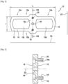
- the fixing device 10 comprises a base 12 having an upper face 14 and a lower face 16.
- the upper face 14 is intended to carry the terrace blades 100, 200, while the lower face 16 of the base 12 is pressed against the joist 2.
- the base 12 is made of a plastic material.
- the base comprises a base provided with notches 24 defined between pads 26.
- the pads 26 come to bear against the upper surface of the joist 2.
- the notches 24 provide ventilation under the slats 100, 200, and also allow rainwater to drain away.
- each of the two base portions 12a, 12b comprises recesses 12c , 12d which are bordered by a peripheral edge 15 of the base 12. It is understood that the blades 100, 200 bear on this peripheral edge 15.
- the recesses 12 c and 12d, associated with the notches 24, ensure very good ventilation under the blades 100, 200 and facilitate the evacuation of rainwater.
- the orifice 40 is therefore a through hole and extends in a direction D2 which is parallel to the first direction D1.
- This direction D2 is vertical when the base is placed on the joist 2.
- the centers of the first and second guide members 18, 20 and the center of the orifice 40 are aligned in a direction parallel to the transverse direction of the base 12.
- the orifice 40 is provided in a part forming a bridge connecting the two longitudinal edges 15 a , 15 b of the peripheral edge 15 of the base.
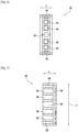
- the housing 50 comprises a first cavity 52 for receiving the first guide member 18, and a second cavity 54 for receiving the second guide member 20 when the housing 50 is mounted on the base 12.
- the housing 5 cooperates with the first and second guide members 18, 20 so that the housing 50 is mounted to slide relative to the base 12 in the first direction D1.
- the housing 50 further comprises cells 56 which, considered along the length x of the housing 50, are arranged between the first and second cavities 52, 54.
- the cells 56 allow the housing 50 to be crushed on itself along its width y, in particular during horizontal expansion of the blades.
- the housing 50 further comprises a hole 60 which extends along the height z of the housing 50 and which is through. Considered along the longitudinal direction Dx of the housing 50, the hole 60 is located substantially in the middle of the housing 50, between the first and second cavities.
- the housing 50 further comprises an upper wall 58 into which the orifice 60 opens.
- the housing 50 further comprises a slot 64, visible in Figure 7 , which is located under the upper wall 62 and which opens laterally on either side of the width y of the housing 50.
- This slot extends along almost the entire length x of the case, and over its entire width y.
- the fixing device 10, as illustrated in Figure 1 further comprises a holding device 70 which is mounted to the housing 50 and, as illustrated in figures 11 to 14 , is configured to be engaged in the grooves 104, 204 of the terrace blades 100, 200.
- the holding element 70 projects on either side of the width of the housing.
- the holding element 70 is an insert 72, metallic in this example, which is secured to the housing 50. More precisely, the insert 72 has the shape of a plate 74 which is arranged in the slot 64 of the housing 50.
- the plate 74 therefore comprises a first portion 74 a projecting relative to the housing 50 and forming a first fin.
- the plate 74 further comprises a second portion 74 b projecting relative to the housing 50 and forming a second fin opposite the first fin.
- the insert 72 is illustrated in more detail in figures 9 and 10 The plate protrudes on either side of the longitudinal edges of the case .
- the plate 74 has an opening 76 which is through depending on the thickness of the plate 74.
- the housing 50 is made of plastic and is overmolded with the metal plate 74.
- the hole 60 of the housing 50 and the opening 76 of the plate 74 are coaxial.
- the hole 60 of the housing 50 is radially recessed relative to the opening 76 of the plate 74.
- the diameter of the hole 60 of the housing 50 is larger than the diameter of the opening 76.
- the plate 74 is provided with claws 75 which extend from a lateral edge 74 c of the plate. These claws are configured to bear in a wall of the groove of the blade.
- the claws 75 are configured to come to bear in a lower wall 102a of the groove 104 of the first blade 100.
- the plate 74 further has a lateral edge 74d opposite the lateral edge 74c , this lateral edge 74d having a fold or bead 77.
- the bead 77 is configured to come into contact with a lower wall 204a of the groove 204 of the second blade 200.
- the fastening device 10 further comprises a locking element 80 which is configured to secure the fastening device and the blade to the support.
- the locking element 80 is a screw which comprises a threaded rod 82 having a first end 82 a provided with a head 84, and a second longitudinal end 82 b provided with a self-piercing tip 86.
- This installation 500 comprises a support consisting of a joist 2, first and second terrace boards 100, 200 having a thickness e 1 .
- the groove 104 of the first board 100 comprises a lower wall 104 a
- the groove 204 comprises a lower wall 204 a.
- the lower walls 104 a, 204 a are parallel to the upper face of the base 12.
- the installation 500 further comprises a fixing device 10 according to the invention, namely that of the Figure 1
- the grooves 104, 204 of the first and second blades 100, 200 are arranged opposite each other on either side of the housing 50 of the fixing device 10.
- the base 12 of the fixing device 10 is placed on the support 2, while the holding element 70 of the fixing device 10 is engaged in the grooves 102, 202.
- the locking element 80 is engaged successively in the holding element 70, in the housing 50 so as to press the first and second blades 100, 200 and the base 12 against the support 2.
- the behavior of the fixing device 10 according to the invention has been illustrated in a situation in which the blades 100 and 200 expand, for example due to an increase in the humidity of the air which causes the blades to swell.
- the housing 50 and the lugs 18, 20 of the base 12 are deformable. More precisely, they can be slightly crushed on themselves in a horizontal plane.
Landscapes
- Engineering & Computer Science (AREA)
- Architecture (AREA)
- Civil Engineering (AREA)
- Structural Engineering (AREA)
- Connection Of Plates (AREA)
- Clamps And Clips (AREA)
- Supports For Plants (AREA)
Claims (15)
- Befestigungsvorrichtung (10) zum Befestigen mindestens einer Terrassendiele (100, 200), die eine Längskante (102, 202) aufweist, die mit einer Nut (104, 204) versehen ist, an einem Träger (S), die Befestigungsvorrichtung umfassend:eine Basis (12), die eine Oberseite (14) aufweist, die Basis umfassend mindestens ein erstes Führungsteil (18, 20) umfasst, das senkrecht zu der Oberseite (14) in einer ersten Richtung (D1) hervorsteht, wobei die Basis eine Länge, die eine Längsrichtung (DL) definiert, und eine Breite, die eine Querrichtung definiert, aufweist;ein Gehäuse (50), das eine Länge (x), eine Breite (y) und eine Höhe (z) aufweist;ein Halteelement (70), das an dem Gehäuse (50) montiert und konfiguriert ist, um zumindest in der Nut (104, 204) der Terrassendiele (100, 200) eingegriffen zu sein, wobei das Halteelement (70) auf beiden Seiten der Breite des Gehäuses hervorsteht; undein Verriegelungselement (80), das konfiguriert ist, um die Befestigungsvorrichtung fest mit dem Träger zu verbinden,dadurch gekennzeichnet, dass das Gehäuse (50) mindestens einen ersten Hohlraum (52, 54) zum Aufnehmen des ersten Führungsteils (18, 20) umfasst, sodass das Gehäuse (50) in Bezug auf die Basis (12) in der ersten Richtung (D1) gleitend montiert ist.
- Befestigungsvorrichtung nach Anspruch 1, wobei, betrachtet in der Längsrichtung (DL) der Basis (12), die Oberseite (14) der Basis (12) zwei Basisabschnitte (12a, 12b) umfasst, die auf beiden Seiten des ersten Führungsteils (18, 20) angeordnet sind, um zwei Terrassendielen (100, 200) aufzunehmen, mindestens einer der Basisabschnitte (12a, 12b) umfassend eine Aussparung (12c, 12d), die von einer Umfangskante (15) begrenzt wird.
- Befestigungsvorrichtung nach Anspruch 1 oder 2, wobei die Basis (12) einen Fuß (22) umfasst, der mit Schlitzen (24) versehen ist.
- Befestigungsvorrichtung nach einem der vorherigen Ansprüche, dadurch gekennzeichnet, dass die Basis (12) eine Öffnung (40) umfasst, die durchgehend ist und sich in einer Richtung (D2) parallel zu der ersten Richtung erstreckt, wobei die Öffnung (40) geformt ist, um das Verriegelungselement (80) aufzunehmen, wenn die Befestigungsvorrichtung (10) fest mit dem Träger verbunden ist.
- Befestigungsvorrichtung nach Anspruch 4, wobei die Basis ein zweites Führungsteil (20) umfasst, wobei das erste und das zweite Führungsteil (18, 20) auf beiden Seiten der Öffnung (40) angeordnet sind, vorzugsweise entlang der Breite () der Basis.

- Befestigungsvorrichtung nach Anspruch 5, wobei das Gehäuse (50) mindestens einen zweiten Hohlraum (54) zum Aufnehmen des zweiten Führungsteils (20) umfasst.
- Befestigungsvorrichtung nach einem der vorherigen Ansprüche, wobei das Gehäuse (50) ferner ein Loch (60) umfasst, das sich entlang der Höhe (z) des Gehäuses (50) erstreckt und das durchgehend ist, wobei das Loch (60) geformt ist, um das Verriegelungselement (80) aufzunehmen, wenn die Befestigungsvorrichtung (10) fest mit dem Träger verbunden ist.
- Befestigungsvorrichtung nach einem der vorherigen Ansprüche, wobei das Halteelement (70) ein Einsatz (72), vorzugsweise aus Metall, ist, der an dem Gehäuse (50) befestigt ist.
- Befestigungsvorrichtung nach einem der vorherigen Ansprüche, wobei das Halteelement (70) die Form eines Plättchens (74) aufweist, das mit einer Öffnung versehen ist, wobei die Öffnung (76) geformt ist, um das Verriegelungselement (80) aufzunehmen, wenn die Befestigungsvorrichtung fest mit dem Träger verbunden ist.
- Befestigungsvorrichtung nach den Ansprüchen 7 und 9, wobei das Loch (60) des Gehäuses (50) und die Öffnung (76) des Plättchens (74) koaxial sind, das Loch (60) des Gehäuses (50) radial von der Öffnung (76) zurückgesetzt ist, wodurch das Verriegelungselement (80) an der Plättchen anliegt, wenn die Befestigungsvorrichtung fest mit dem Träger verbunden ist.
- Befestigungsvorrichtung nach Anspruch 9 oder 10, wobei das Plättchen (74) eine Seitenkante (74c) aufweist, die mit Krallen (75) versehen ist, die konfiguriert sind, um in einer Wand (104a) der Nut der Diele (100) anzuliegen.
- Befestigungsvorrichtung nach den vorherigen Ansprüchen, wobei das Verriegelungselement eine Schraube (82) umfasst, die einen Schraubenkopf (84) umfasst, und wobei der Schraubenkopf an dem Halteelement (70) anliegt, wenn die Befestigungsvorrichtung fest mit dem Träger verbunden ist.
- Befestigungsvorrichtung nach den Ansprüchen 4, 7 und 9, wobei die Öffnung (40) der Basis (12), das Loch (60) des Gehäuses (50) und die Öffnung (76) des Halteelements (70) ausgerichtet und geformt sind, um von dem Verriegelungselement (80) durchdrungen zu werden, wenn die Befestigungsvorrichtung fest mit dem Träger verbunden ist.
- Befestigungsvorrichtung nach einem der vorherigen Ansprüche, wobei das Gehäuse (50) Zellen (56) umfasst, um entlang seiner Breite auf sich selbst zusammengedrückt zu werden.
- Installation (500, 600), umfassend einen Träger (2), eine erste und eine zweite Terrassendiele (100, 200) und mindestens eine Befestigungsvorrichtung (10) nach einem der vorherigen Ansprüche, wobei jede von der ersten und der zweiten Diele (100, 200) eine Nut (104, 204) aufweist, die entlang mindestens einer ihrer Längskanten (102, 202) ausgebildet ist, wobei die Nuten der ersten und der zweiten Diele (100, 200) auf beiden Seiten des Gehäuses (50) der Befestigungsvorrichtung (10) einander gegenüberliegend angeordnet sind,
die Basis (12) der Befestigungsvorrichtung (10) von dem Träger (2) aufgesetzt wird, während das Halteelement (70) der Befestigungsvorrichtung in die Nuten (104, 204) eingegriffen ist, das Verriegelungselement (20) mit dem Halteelement (70), dem Gehäuse (50) und der Basis (12) und dem Träger (2) eingegriffen ist, um eine Kraft auf das Halteelement auszuüben, die gegen den Träger (2) gerichtet ist, sodass die erste und die zweite Diele und die Basis (12) zusammengepresst werden.
Applications Claiming Priority (1)
| Application Number | Priority Date | Filing Date | Title |
|---|---|---|---|
| FR2102442A FR3120642B1 (fr) | 2021-03-12 | 2021-03-12 | Dispositif de fixation de lames de terrasse à un support |
Publications (3)
| Publication Number | Publication Date |
|---|---|
| EP4056783A1 EP4056783A1 (de) | 2022-09-14 |
| EP4056783B1 true EP4056783B1 (de) | 2025-06-25 |
| EP4056783C0 EP4056783C0 (de) | 2025-06-25 |
Family
ID=75539605
Family Applications (1)
| Application Number | Title | Priority Date | Filing Date |
|---|---|---|---|
| EP22160820.1A Active EP4056783B1 (de) | 2021-03-12 | 2022-03-08 | Vorrichtung zur befestigung von terrassendielen an eine unterlage |
Country Status (2)
| Country | Link |
|---|---|
| EP (1) | EP4056783B1 (de) |
| FR (1) | FR3120642B1 (de) |
Family Cites Families (5)
| Publication number | Priority date | Publication date | Assignee | Title |
|---|---|---|---|---|
| FR2864568B3 (fr) | 2003-12-31 | 2005-12-16 | Forestia | Dispositif de fixation de lames, notamment de lames de plancher equipe d'au moins un dispositif tel que precite |
| US8806829B2 (en) * | 2004-10-01 | 2014-08-19 | The Ipé Clip Fastener Company, LLC | Anchoring device |
| WO2011163653A2 (en) * | 2010-06-25 | 2011-12-29 | Omg, Inc | Hidden fastener formed in situ during attachment of sheathing onto a support member |
| US20160362902A1 (en) * | 2015-06-15 | 2016-12-15 | Elmich Pte Ltd | Fastening system for decking boards |
| IT201800010700A1 (it) * | 2018-11-29 | 2020-05-29 | Heco Italia Efg S R L | Gruppo di aggancio per pannelli |
-
2021
- 2021-03-12 FR FR2102442A patent/FR3120642B1/fr active Active
-
2022
- 2022-03-08 EP EP22160820.1A patent/EP4056783B1/de active Active
Also Published As
| Publication number | Publication date |
|---|---|
| FR3120642A1 (fr) | 2022-09-16 |
| FR3120642B1 (fr) | 2024-02-23 |
| EP4056783A1 (de) | 2022-09-14 |
| EP4056783C0 (de) | 2025-06-25 |
Similar Documents
| Publication | Publication Date | Title |
|---|---|---|
| EP1440214B1 (de) | Vorrichtung zum zusammenfügen von den rändern von platten | |
| CA2628810C (fr) | Procede de montage de lames sur une structure de support et organe de fixation ameliore | |
| EP2310734B1 (de) | Spannvorrichtung mit klemmschelle | |
| FR2903707A1 (fr) | Element de fixation pour lame de couverture de surface et lame de couverture de surface adaptee a un tel element de fixation | |
| EP1945881B1 (de) | Verfahren zur befestigung von blättern an einer stützstruktur und verbessertes befestigungselement | |
| FR2826391A1 (fr) | Dispositif d'assemblage des bords de panneaux, lattes ou lambris | |
| FR2950371A1 (fr) | Systeme de fixation d'une dalle pour terrasse | |
| WO2013079879A1 (fr) | Dispositif d'entretoise pour un dispositif de fixation d'un objet sur un mur habille avec une couche d'isolation. | |
| EP4056783B1 (de) | Vorrichtung zur befestigung von terrassendielen an eine unterlage | |
| EP2270290A1 (de) | Befestigungsvorrichtung für Boden | |
| FR2818677A1 (fr) | Systeme pour fixer des lames, notamment des lames de terrasse, piece de fixation mise en oeuvre dans ce systeme, et lame adaptee a ce systeme | |
| EP0273833B1 (de) | Vorrichtung für Schneeauffang auf einem gerippten Blechdach | |
| EP2163703A1 (de) | Verbindung bzw. Gelenk zwischen zwei Hohlprofilen mit einstellbarem Winkel | |
| FR2975716A1 (fr) | Systeme de blocage entre deux lames d'une structure plane de parement ou de parquet. | |
| BE1026538B1 (fr) | Accessoire de fixation d'un panneau de grillage a un poteau de clôture comportant une piece de blocage et une piece de serrage | |
| FR3002257A1 (fr) | Ensemble a lames du type positionnable sur un plan support, piece de fixation mise en œuvre dans ledit ensemble, revetement comprenant au moins ledit ensemble et procede de fixation d'un tel ensemble a un plan support | |
| EP1464260A1 (de) | Fensteranordnung mit einer Gardinenstange | |
| FR2992009A1 (fr) | Dispositif de fixation d'au moins un element de parement sur un support, et ensemble de parement comprenant un tel dispositif de fixation | |
| EP4374026A1 (de) | Unsichtbares befestigungssystem | |
| EP1647723B1 (de) | Rohrendstück, insbesondere für Leiter- oder Trittleiterholmen, und Montageverfahren | |
| FR3149634A1 (fr) | Ensemble formant profilé bandeau, destiné à être fixé à l’ouvrant, respectivement le dormant, d’une porte dont l’ouverture/fermeture est réalisée par une serrure électromagnétique | |
| EP3073022B1 (de) | Dachziegel mit steckverbindung | |
| EP1980682B1 (de) | Ortgangziegel mit Lasche | |
| FR2826392A1 (fr) | Dispositif d'assemblage des bords de panneaux, lattes ou lambris | |
| FR2683249A1 (fr) | Piquet pour cloture. |
Legal Events
| Date | Code | Title | Description |
|---|---|---|---|
| PUAI | Public reference made under article 153(3) epc to a published international application that has entered the european phase |
Free format text: ORIGINAL CODE: 0009012 |
|
| STAA | Information on the status of an ep patent application or granted ep patent |
Free format text: STATUS: THE APPLICATION HAS BEEN PUBLISHED |
|
| AK | Designated contracting states |
Kind code of ref document: A1 Designated state(s): AL AT BE BG CH CY CZ DE DK EE ES FI FR GB GR HR HU IE IS IT LI LT LU LV MC MK MT NL NO PL PT RO RS SE SI SK SM TR |
|
| STAA | Information on the status of an ep patent application or granted ep patent |
Free format text: STATUS: REQUEST FOR EXAMINATION WAS MADE |
|
| 17P | Request for examination filed |
Effective date: 20230309 |
|
| RBV | Designated contracting states (corrected) |
Designated state(s): AL AT BE BG CH CY CZ DE DK EE ES FI FR GB GR HR HU IE IS IT LI LT LU LV MC MK MT NL NO PL PT RO RS SE SI SK SM TR |
|
| STAA | Information on the status of an ep patent application or granted ep patent |
Free format text: STATUS: EXAMINATION IS IN PROGRESS |
|
| 17Q | First examination report despatched |
Effective date: 20240613 |
|
| 17Q | First examination report despatched |
Effective date: 20240626 |
|
| GRAP | Despatch of communication of intention to grant a patent |
Free format text: ORIGINAL CODE: EPIDOSNIGR1 |
|
| STAA | Information on the status of an ep patent application or granted ep patent |
Free format text: STATUS: GRANT OF PATENT IS INTENDED |
|
| INTG | Intention to grant announced |
Effective date: 20250319 |
|
| GRAS | Grant fee paid |
Free format text: ORIGINAL CODE: EPIDOSNIGR3 |
|
| GRAA | (expected) grant |
Free format text: ORIGINAL CODE: 0009210 |
|
| STAA | Information on the status of an ep patent application or granted ep patent |
Free format text: STATUS: THE PATENT HAS BEEN GRANTED |
|
| AK | Designated contracting states |
Kind code of ref document: B1 Designated state(s): AL AT BE BG CH CY CZ DE DK EE ES FI FR GB GR HR HU IE IS IT LI LT LU LV MC MK MT NL NO PL PT RO RS SE SI SK SM TR |
|
| REG | Reference to a national code |
Ref country code: GB Ref legal event code: FG4D Free format text: NOT ENGLISH |
|
| REG | Reference to a national code |
Ref country code: CH Ref legal event code: EP |
|
| REG | Reference to a national code |
Ref country code: CH Ref legal event code: EP |
|
| REG | Reference to a national code |
Ref country code: IE Ref legal event code: FG4D Free format text: LANGUAGE OF EP DOCUMENT: FRENCH |
|
| REG | Reference to a national code |
Ref country code: DE Ref legal event code: R096 Ref document number: 602022016283 Country of ref document: DE |
|
| U01 | Request for unitary effect filed |
Effective date: 20250718 |
|
| U07 | Unitary effect registered |
Designated state(s): AT BE BG DE DK EE FI FR IT LT LU LV MT NL PT RO SE SI Effective date: 20250725 |
|
| PG25 | Lapsed in a contracting state [announced via postgrant information from national office to epo] |
Ref country code: NO Free format text: LAPSE BECAUSE OF FAILURE TO SUBMIT A TRANSLATION OF THE DESCRIPTION OR TO PAY THE FEE WITHIN THE PRESCRIBED TIME-LIMIT Effective date: 20250925 Ref country code: GR Free format text: LAPSE BECAUSE OF FAILURE TO SUBMIT A TRANSLATION OF THE DESCRIPTION OR TO PAY THE FEE WITHIN THE PRESCRIBED TIME-LIMIT Effective date: 20250926 |
|
| PG25 | Lapsed in a contracting state [announced via postgrant information from national office to epo] |
Ref country code: HR Free format text: LAPSE BECAUSE OF FAILURE TO SUBMIT A TRANSLATION OF THE DESCRIPTION OR TO PAY THE FEE WITHIN THE PRESCRIBED TIME-LIMIT Effective date: 20250625 |
|
| PG25 | Lapsed in a contracting state [announced via postgrant information from national office to epo] |
Ref country code: RS Free format text: LAPSE BECAUSE OF FAILURE TO SUBMIT A TRANSLATION OF THE DESCRIPTION OR TO PAY THE FEE WITHIN THE PRESCRIBED TIME-LIMIT Effective date: 20250925 |
|
| PG25 | Lapsed in a contracting state [announced via postgrant information from national office to epo] |
Ref country code: IS Free format text: LAPSE BECAUSE OF FAILURE TO SUBMIT A TRANSLATION OF THE DESCRIPTION OR TO PAY THE FEE WITHIN THE PRESCRIBED TIME-LIMIT Effective date: 20251025 |
|
| PG25 | Lapsed in a contracting state [announced via postgrant information from national office to epo] |
Ref country code: SM Free format text: LAPSE BECAUSE OF FAILURE TO SUBMIT A TRANSLATION OF THE DESCRIPTION OR TO PAY THE FEE WITHIN THE PRESCRIBED TIME-LIMIT Effective date: 20250625 |