EP1560685B1 - Schneidverfahren mit linearzuführung - Google Patents
Schneidverfahren mit linearzuführung Download PDFInfo
- Publication number
- EP1560685B1 EP1560685B1 EP20030754497 EP03754497A EP1560685B1 EP 1560685 B1 EP1560685 B1 EP 1560685B1 EP 20030754497 EP20030754497 EP 20030754497 EP 03754497 A EP03754497 A EP 03754497A EP 1560685 B1 EP1560685 B1 EP 1560685B1
- Authority
- EP
- European Patent Office
- Prior art keywords
- workpiece
- cutting
- cut
- blade
- angle
- Prior art date
- Legal status (The legal status is an assumption and is not a legal conclusion. Google has not performed a legal analysis and makes no representation as to the accuracy of the status listed.)
- Expired - Lifetime
Links
Images


Classifications
-
- B—PERFORMING OPERATIONS; TRANSPORTING
- B27—WORKING OR PRESERVING WOOD OR SIMILAR MATERIAL; NAILING OR STAPLING MACHINES IN GENERAL
- B27B—SAWS FOR WOOD OR SIMILAR MATERIAL; COMPONENTS OR ACCESSORIES THEREFOR
- B27B5/00—Sawing machines working with circular or cylindrical saw blades; Components or equipment therefor
- B27B5/16—Saw benches
- B27B5/18—Saw benches with feedable circular saw blade, e.g. arranged on a carriage
- B27B5/20—Saw benches with feedable circular saw blade, e.g. arranged on a carriage the saw blade being adjustable according to depth or angle of cut; Radial saws, i.e. sawing machines with a pivoted radial arm for guiding the movable carriage
- B27B5/208—Saw benches with feedable circular saw blade, e.g. arranged on a carriage the saw blade being adjustable according to depth or angle of cut; Radial saws, i.e. sawing machines with a pivoted radial arm for guiding the movable carriage the saw blade being mounted on a hanging arm or at the end of a set of bars, e.g. parallelograms
-
- B—PERFORMING OPERATIONS; TRANSPORTING
- B27—WORKING OR PRESERVING WOOD OR SIMILAR MATERIAL; NAILING OR STAPLING MACHINES IN GENERAL
- B27B—SAWS FOR WOOD OR SIMILAR MATERIAL; COMPONENTS OR ACCESSORIES THEREFOR
- B27B25/00—Feeding devices for timber in saw mills or sawing machines; Feeding devices for trees
- B27B25/02—Feeding devices for timber in saw mills or sawing machines; Feeding devices for trees with feed and pressure rollers
-
- B—PERFORMING OPERATIONS; TRANSPORTING
- B27—WORKING OR PRESERVING WOOD OR SIMILAR MATERIAL; NAILING OR STAPLING MACHINES IN GENERAL
- B27B—SAWS FOR WOOD OR SIMILAR MATERIAL; COMPONENTS OR ACCESSORIES THEREFOR
- B27B5/00—Sawing machines working with circular or cylindrical saw blades; Components or equipment therefor
- B27B5/16—Saw benches
- B27B5/18—Saw benches with feedable circular saw blade, e.g. arranged on a carriage
- B27B5/20—Saw benches with feedable circular saw blade, e.g. arranged on a carriage the saw blade being adjustable according to depth or angle of cut; Radial saws, i.e. sawing machines with a pivoted radial arm for guiding the movable carriage
- B27B5/207—Saw benches with feedable circular saw blade, e.g. arranged on a carriage the saw blade being adjustable according to depth or angle of cut; Radial saws, i.e. sawing machines with a pivoted radial arm for guiding the movable carriage the saw blade being fitted on a movable carriage
-
- Y—GENERAL TAGGING OF NEW TECHNOLOGICAL DEVELOPMENTS; GENERAL TAGGING OF CROSS-SECTIONAL TECHNOLOGIES SPANNING OVER SEVERAL SECTIONS OF THE IPC; TECHNICAL SUBJECTS COVERED BY FORMER USPC CROSS-REFERENCE ART COLLECTIONS [XRACs] AND DIGESTS
- Y10—TECHNICAL SUBJECTS COVERED BY FORMER USPC
- Y10T—TECHNICAL SUBJECTS COVERED BY FORMER US CLASSIFICATION
- Y10T83/00—Cutting
- Y10T83/04—Processes
- Y10T83/05—With reorientation of tool between cuts
-
- Y—GENERAL TAGGING OF NEW TECHNOLOGICAL DEVELOPMENTS; GENERAL TAGGING OF CROSS-SECTIONAL TECHNOLOGIES SPANNING OVER SEVERAL SECTIONS OF THE IPC; TECHNICAL SUBJECTS COVERED BY FORMER USPC CROSS-REFERENCE ART COLLECTIONS [XRACs] AND DIGESTS
- Y10—TECHNICAL SUBJECTS COVERED BY FORMER USPC
- Y10T—TECHNICAL SUBJECTS COVERED BY FORMER US CLASSIFICATION
- Y10T83/00—Cutting
- Y10T83/162—With control means responsive to replaceable or selectable information program
- Y10T83/173—Arithmetically determined program
-
- Y—GENERAL TAGGING OF NEW TECHNOLOGICAL DEVELOPMENTS; GENERAL TAGGING OF CROSS-SECTIONAL TECHNOLOGIES SPANNING OVER SEVERAL SECTIONS OF THE IPC; TECHNICAL SUBJECTS COVERED BY FORMER USPC CROSS-REFERENCE ART COLLECTIONS [XRACs] AND DIGESTS
- Y10—TECHNICAL SUBJECTS COVERED BY FORMER USPC
- Y10T—TECHNICAL SUBJECTS COVERED BY FORMER US CLASSIFICATION
- Y10T83/00—Cutting
- Y10T83/202—With product handling means
- Y10T83/2074—Including means to divert one portion of product from another
- Y10T83/2087—Diverging product movers
-
- Y—GENERAL TAGGING OF NEW TECHNOLOGICAL DEVELOPMENTS; GENERAL TAGGING OF CROSS-SECTIONAL TECHNOLOGIES SPANNING OVER SEVERAL SECTIONS OF THE IPC; TECHNICAL SUBJECTS COVERED BY FORMER USPC CROSS-REFERENCE ART COLLECTIONS [XRACs] AND DIGESTS
- Y10—TECHNICAL SUBJECTS COVERED BY FORMER USPC
- Y10T—TECHNICAL SUBJECTS COVERED BY FORMER US CLASSIFICATION
- Y10T83/00—Cutting
- Y10T83/647—With means to convey work relative to tool station
- Y10T83/6476—Including means to move work from one tool station to another
-
- Y—GENERAL TAGGING OF NEW TECHNOLOGICAL DEVELOPMENTS; GENERAL TAGGING OF CROSS-SECTIONAL TECHNOLOGIES SPANNING OVER SEVERAL SECTIONS OF THE IPC; TECHNICAL SUBJECTS COVERED BY FORMER USPC CROSS-REFERENCE ART COLLECTIONS [XRACs] AND DIGESTS
- Y10—TECHNICAL SUBJECTS COVERED BY FORMER USPC
- Y10T—TECHNICAL SUBJECTS COVERED BY FORMER US CLASSIFICATION
- Y10T83/00—Cutting
- Y10T83/647—With means to convey work relative to tool station
- Y10T83/6582—Tool between tandem arranged work carrying means
-
- Y—GENERAL TAGGING OF NEW TECHNOLOGICAL DEVELOPMENTS; GENERAL TAGGING OF CROSS-SECTIONAL TECHNOLOGIES SPANNING OVER SEVERAL SECTIONS OF THE IPC; TECHNICAL SUBJECTS COVERED BY FORMER USPC CROSS-REFERENCE ART COLLECTIONS [XRACs] AND DIGESTS
- Y10—TECHNICAL SUBJECTS COVERED BY FORMER USPC
- Y10T—TECHNICAL SUBJECTS COVERED BY FORMER US CLASSIFICATION
- Y10T83/00—Cutting
- Y10T83/768—Rotatable disc tool pair or tool and carrier
- Y10T83/7684—With means to support work relative to tool[s]
- Y10T83/7693—Tool moved relative to work-support during cutting
- Y10T83/7697—Tool angularly adjustable relative to work-support
-
- Y—GENERAL TAGGING OF NEW TECHNOLOGICAL DEVELOPMENTS; GENERAL TAGGING OF CROSS-SECTIONAL TECHNOLOGIES SPANNING OVER SEVERAL SECTIONS OF THE IPC; TECHNICAL SUBJECTS COVERED BY FORMER USPC CROSS-REFERENCE ART COLLECTIONS [XRACs] AND DIGESTS
- Y10—TECHNICAL SUBJECTS COVERED BY FORMER USPC
- Y10T—TECHNICAL SUBJECTS COVERED BY FORMER US CLASSIFICATION
- Y10T83/00—Cutting
- Y10T83/869—Means to drive or to guide tool
- Y10T83/8773—Bevel or miter cut
Definitions
- This invention relates, in general, to a method for the cutting of wood components, namely, dimension lumber into finished rafters having predetermined lengths and angles at the ends thereof, for use in building construction.
- this invention relates to an apparatus, including a novel linear feed table and adjustable cutting device, for processing workpieces into finished components for assembly, and to a computer control and program for controlling same.
- dimension lumber Most lumber used in the construction industry is known as dimension lumber, which the present invention is intended to use.
- Dimension lumber has opposite sides parallel, with adjacent sides forming a right angle, and is generally known by the nominal dimensions of the sides, e.g., 2x4, 2x6, 4x8, etc.
- the longer sides hereinafter are called “faces,” and the shorter sides are called “edges.”
- the pieces of dimension lumber to be processed by the present invention are called “workpieces” herein and, after cutting or processing, are called “components,” e.g., rafters of several kinds, and webs and chords for trusses.
- the present invention is also useful in cutting all of the webs and chords for a single truss in one operation.
- an individual component for a number of trusses was made up at the same time, to reduce the amount of hand adjustment, and therefore cost, per component. Otherwise, it became very expensive to produce them for a single truss, since adjustments had to be made between the cutting of each different component.
- workpieces were fed into a cutting apparatus laterally, as opposed to linearly, as in the present invention.. Lateral feed assemblies allow for simultaneous cutting of the ends of the workpieces, but are not as efficient where the saw blades must reset between each workpiece.
- FIGS. 1A-C of the drawings herein disclose three typical arrangements of rafters and their associated support or supported members, and will help to illustrate the concepts of "measuring line” and "ridge line”;
- the first structure of FIG. 1C is an older method of construction little used at the present time.
- FIGS. 1B AND 1A represent methods of construction which are more widely used at present.
- Regular rafters i.e., those on which the ends are cut at right angles to the faces (or the edges), even though the ends may be cut at something other than a right angle to the edges (or the faces, respectively), do not present a great problem to manufacture, since the length of a given rafter as measured on one face (or edge) is the same as the length measured on the other face (or edge).
- hip, valley, and jack rafters present a more difficult problem of manufacture:
- U.S. Pat.No. 4,545,274 teaches a means of tilting the axis of travel of a saw blade to correspond to the complement of the roof slope, and then angling the saw blade to make the compound cut. Lumber is moved past the cutting station in a sideways manner. A separate cutting station is required for cuts on the other end of the component and, to cut components of differing lengths, one of the cutting stations must be movable in relation to the other, which takes time. Further, the cutting process is not automatic.
- U.S. Pat.No. 6,212,983 referred to herein teaches a linear feed system where compound cuts are achieved by tilting the work surface supporting the workpiece. This requires automating and adjusting the work surface to be movable for compound cuts. Adjusting workpieces of great length may prove cumbersome.
- An example of a lateral feed assembly can be found in Shamblin, U. S. Pat. No. 5,943,239 , which is referred to herein. Such a system employs four or more cutters and requires more work space and added expense.
- FIGS. 1A-C are profile views of regular rafters as used in three typical installings, disclosing the parameters which establish the measuring and cutting points for the operation of the present invention.
- FIG. 2 is an oblique view of a hip roof and its components, including rafters, showing the important structural relationships thereof.
- FIG. 3 is an oblique view of a jack rafter, with the important lines and angles indicated thereon.
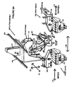
- FIG. 4 is a top view of the present invention, disclosing the arrangement of the various major elements thereof.
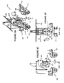
- FIG. 5A is an orthogonal view of the cutting assembly in position to make a compound or bevel cut
- FIG. 5B is an orthogonal view of the cutting assembly in a home position
- FIG. 5C is a front view of the cutting assembly
- FIG. 5D is a right elevational view of the cutting assembly
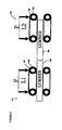
- FIG. 6 is a detail schematic elevational view of the feeder assembly
- FIG. 7 is a detail elevational view of a component sorter
- FIG. 8 is a sample workpiece
- FIG. 9 is a schematic showing operation of the cutting assembly to create a scarf cut.
- the present invention is an apparatus for making roof structure and other components from dimension lumber workpieces by making the required cuts in a sequential manner. Components such as hip, valley, and jack rafters, and webs and chords for trusses, are easily obtained.
- workpiece refers to the unprocessed, or partially processed pieces of dimension lumber, while “component” refers only to the finished piece, after all processing has been performed.
- FIGS. 1-3 it will be helpful to refer to FIGS. 1-3 , in understanding the following preliminary description.
- Regular rafters as disclosed in FIGS. 1A-C , and especially as disclosed in place in FIG. 2 , although having the ends thereof cut at angles other than a right angle to the rafter edges, have a right angle between the end of the rafter and its faces, requiring only that the cutting tool be at the proper angle to the edges to make the cut.
- Hip, valley, and jack rafters require that the cutting tool cut at compound angles, sometimes on the same workpiece and on the same end thereof:
- FIG. 4 discloses, in a view from the top, the overall structure of the wood-handling apparatus 100.
- the wood-handling apparatus 100 preferably includes a live deck 102 for automatically supplying workpieces 104 to the infeed assembly 106.
- the infeed assembly 106 supplies workpieces 104, one at a time, in a linear feed, to the cutting assembly 200.
- the out-feed assembly 110 moves finished components 112 away from the cutting assembly 108.
- the cutting assembly 200 is shown in more detail in FIGS. 5A-5D .
- the cutting assembly 200 has at least one cutting blade 202, here shown as a circular saw blade.
- FIG. 4 shows an optimal arrangement of a cutting assembly 200 with multiple cutting blades 201 and 202.
- Cutting element 202 is mounted on saw-frame 204 and is movable in several directions. Element 202 is rotatable about its vertical axis V1, allowing motion of the element 202 as shown by arrow A1. The cutting element 202 is shown in its upright or home position 204 in FIG.5B . The cutting element 202 also moves vertically, allowing movement as indicated by the arrow Z1. The cutting element 202 is movable transversely, across the workpiece 104, as indicated by arrow T1. The cutting element 202 is finally rotatable about axis C1, allowing movement as indicated by arrow B1. Movement of the workpiece along path L is controlled by linear feed assembly 300, the infeed feeder 302 and outfeed feeder 304 allowing lumber movement as indicated by arrow LM.
- the practitioner will realize that the combination of movements allowed by the feed assembly 300 and cutting assembly 200 will enable simple and compound cuts to be made to a workpiece.
- the cutting assembly 300 is in position for a compound cut in FIG. 5A .
- the saw frame 204 is mounted to a stable object, such as a saw enclosure 206.
- the frame 204 is slidably mounted to transverse rails 208.
- the frame 204 is movable in the transverse direction, along arrow T1, by movement along a ball-screw shaft (not shown) which interacts with aperture 210 in a manner know in the art.
- Piston-cylinder assembly 212 controls the movement of the cutting element 202 in the vertical plane, Z1. Rotation of the cutting element 202 is controlled by servomotor and pulleys 214 allowing motion indicated by arrow B1.
- actuator 216 rotation about the vertical pivot, movement along line A1 is controlled by an actuator 216.
- movement in the transverse direction moves actuators 212, 214 and 216 along with all of frame 204.
- This arrangement can be modified as desired as long as movement is allowed in the desired directions.
- the preferred embodiment utilizes, convenient actuator mechanisms but any means known in the art may be used to effect the various movements of the cutting elements.
- Linear movement of the workpiece is handled by the linear feeder 300, namely the infeed feeder 302 and the outfeed feeder 304.
- Each feeder 302 and 304 has an upper component, 306 and 308, and a lower component 310 and 312, respectively.
- the upper components, 306 and 308, are the drive components.
- the upper components 306 and 308 are movable in the Z axis allowing the upper components to clamp down on a workpiece to effectuate movement thereof.
- the linear feeder 300 further comprises sensors (not shown) for sensing the presence of a workpiece and locating the end thereof. Use of such sensors is known in the art.
- the upper components 306 and 308, seen in detail FIG. 6 have belts that press against the lumber and grip it against the lower components 310 and 312.
- the drive mechanism for the belt is a servomotor with a measuring device or encoder, that measures the length of the workpiece as it feeds the lumber
- Other drive mechanisms 324 and encoders 322 may be used, as are known in the art.
- the two units 302 and 304 are capable of working together, moving a single workpiece at the same rate, or independently.
- any workpiece that extends at least half-way through either feeder will be held steady enough to cut Pressure can be supplied by springs, hydraulics or other known methods.
- the feed rolls shown are believed to provide better length measuring accuracy because they are not subject to errors introduced by warped lumber or surface imperfections.
- Other roller, drive and measuring means may be used, such as that described in U.S. Pat. No. 6,263, 773 to McAdoo which is hereby incorporated for all purposes.
- the computer 400 determines the manner in which to position the saw blade, actuates all motion of the blade elements and rollers, tracks the presence and length of workpieces, and operates to cut workpieces to the required length and shape.
- the cutting assembly and roller feed assemblies are operably connected to the computer 400 through appropriate electronics as are known in the art.
- the computer enables the user to input the desired lengths of wood product needed for a particular job.
- the computer may optimize the cuts made in the wood product through an appropriate program.
- the computer controls the cutting unit and the driving unit.
- the computer receives input signals from at least the position sensors and encoders.
- the computer is operably connected to activate and control the driver assembly and pressure assembly for positioning the workpieces and the cutting unit.
- the computer receives input from the measuring assembly to determine the length of the workpiece and to determine the appropriate positioning of the workpiece in selecting the locations of the cuts to be made.
- the computer may optimize the cuts in the product by a method such as the one disclosed in U.S. Pat. No. 5,444,635 to Blaine , which is referred to herein.
- the second cutting assembly 201 is similar to the first, 200, but preferably below-mounted such that the cutting blade moves upward to execute a cut.
- the second cutting assembly 201 can be used to execute a cut which the first assembly 200 is positioning itself
- the invention can also be combined with a marking assembly 500 as in known in the art, which can mark workpieces as to their size, shape, dimensions, or any other preferred indication.
- the out feed system 110 can include a sorter, as seen in FIGS. 4 and 7 , as is known in the art, to dump the cut components into carts or other handling mechanisms.
- a sorter as seen in FIGS. 4 and 7 , as is known in the art, to dump the cut components into carts or other handling mechanisms.
- sorters 600 and carts 602, with flip-up arms 604 to direct components is well-known in the art and sorters are commercially available from Alpine Engineered Products, Inc.
- the cutting assembly can cut all types of components, including those with compound or bevel cuts.
- a sensor will detect the presence of a board and activate L1 to start the board into the saw.
- a second sensor will detect the leading edge of the board with sufficient precision to move the board into position for first cut. All subsequent cuts will be under the precise control of the motion control system, so no other adjustments will be needed until a new board is fed into the machine.
- the motion control system will track and adjust for kerf material removed and end configuration resulting from previous cuts.
- FIG. 8 shows a component requiring multiple cuts. With a single-head saw 200, the blade would set up, execute cut 1, reposition and execute cut 2, etc., for all four cuts.
- unit 200 would position and execute cut 1.
- Unit 201 would be positioning itself for cut 2 while cut 1 is being made.
- Unit 201 would then execute cut 2 while unit 200 positioned for cut 3, etc.
- Prior to cut 4 obviously, the linear feeders would forward and position the workpiece for the final cut. An infinite variety of cuts is possible.
- FIG. 9 shows a detail of cutting for scarf cuts.
- the cut length, S required is greater than the maximum cut C of blade 202.
- cut length S will be less than maximum cut C.
- use of automated movement along axis T1 is employed to make a cut as needed.
- the workpiece 104 is shown in place, engaged by feed roller assembly 302.
- the computer 400 positions the cutting blade 202 at the appropriate angle about axis 1, and along other axes as necessary.
- the cutting blade 202 is lowered, along vertical axis Z1, into cutting contact with the workpiece 104, engaging the workpiece to the maximum cut length C.
- the workpiece 104, via feed roller 302 is then moved linearly while simultaneously the cutting blade 202 is moved along the T1 axis, thereby translating the blade to mark scarf cut S.
- This type of cut is not possible without automated movement in the T1 axis.
Landscapes
- Life Sciences & Earth Sciences (AREA)
- Engineering & Computer Science (AREA)
- Mechanical Engineering (AREA)
- Wood Science & Technology (AREA)
- Forests & Forestry (AREA)
- Dovetailed Work, And Nailing Machines And Stapling Machines For Wood (AREA)
- Shearing Machines (AREA)
- Sawing (AREA)
- Dicing (AREA)
Claims (5)
- Verfahren zum automatischen Schneiden eines Werkstücks 104 unter Verwendung eine Computers 400, welcher betreibbar verbunden ist, um die Bewegungen des Schneidblatts 202 und eine lineare Führungs- bzw. Zuführungs-Baugruppe bzw. Linearzuführungsbaugruppe 106, 110 zu steuern bzw. zu regeln, wobei das Werkstück 104 eine Längs- bzw. Longitudinalachse und zwei entgegengesetzte bzw. gegenüberliegende Flächen 11 und zwei entgegengesetzte bzw. gegenüberliegende Kanten 10 aufweist, wobei das Verfahren die Schritte umfasst:Verwenden eines Computers 400, um die lineare Zuführungs-Baugruppe 106 zu betreiben und ein Werkstück 104 automatisch längs bzw. longitudinal zu bewegen;automatisches Positionieren eines Schneidblatts bzw. -messers 202 in einem Winkel zu den zwei entgegengesetzten Flächen 11 des Werkstücks 104, indem das Blatt um eine vertikale Achse V1 rotiert wird;automatisches Positionieren des Schneidblatts 202 in einem Winkel zu den zwei entgegengesetzten Kanten 10 des Werkstückes, indem das Blatt 202 um eine horizontale Gehrungs- bzw. Abschräg- bzw. Fräsachse C1 rotiert wird;automatisches Bewegen des Blatts 202 in Schneidkontakt mit dem Werkstück 104; undautomatisches Bewegen des Schneidblatts 202 und automatisches längs bzw. longitudinal Bewegen des Werkstücks 104 unter Verwendung der linearen Zuführungs-Baugruppe 106, wodurch das Werkstück 104 in einem zusammengesetzten Winkel geschnitten wird, wobei der zusammengesetzte Winkel in einem Winkel bzw. schräg hinsichtlich sowohl der Werkstückflächen 11 als auch der Kanten 10 ist.
- Verfahren nach Anspruch 1, ferner umfassend den Schritt eines Verwendens des Computers 400, um das Blatt 202 entlang einer schrägen bzw. transversalen Achse T1 zu positionieren.
- Verfahren nach Anspruch 1, ferner umfassend den Schritt eines Bewegens des Schneidblatts 202 entlang einer schrägen bzw. transversalen Achse T1 gleichzeitig zu einem längs bzw. longitudinalen Bewegen des Werkstücks 104 unter Verwendung der linearen Zuführungs-Baugruppe 106, wodurch ein schräger Schnitt (engl. "scarf cut") erzeugt wird.
- Verfahren nach Anspruch 1, ferner umfassend den Schritt eines Sortierens bzw. Einsortierens eines fertiggestellten Werkstücks 104.
- Verfahren nach Anspruch 1, ferner umfassend ein Markieren des Werkstücks 104.
Applications Claiming Priority (3)
| Application Number | Priority Date | Filing Date | Title |
|---|---|---|---|
| US10/270,849 US20040069106A1 (en) | 2002-10-14 | 2002-10-14 | Linear feed cutting apparatus and method |
| US270849 | 2002-10-14 | ||
| PCT/US2003/028492 WO2004035271A2 (en) | 2002-10-14 | 2003-09-10 | Linear feed cutting apparatus and method |
Publications (3)
| Publication Number | Publication Date |
|---|---|
| EP1560685A2 EP1560685A2 (de) | 2005-08-10 |
| EP1560685A4 EP1560685A4 (de) | 2007-10-31 |
| EP1560685B1 true EP1560685B1 (de) | 2009-11-11 |
Family
ID=32069020
Family Applications (1)
| Application Number | Title | Priority Date | Filing Date |
|---|---|---|---|
| EP20030754497 Expired - Lifetime EP1560685B1 (de) | 2002-10-14 | 2003-09-10 | Schneidverfahren mit linearzuführung |
Country Status (6)
| Country | Link |
|---|---|
| US (2) | US20040069106A1 (de) |
| EP (1) | EP1560685B1 (de) |
| AU (1) | AU2003272321B2 (de) |
| CA (1) | CA2501455C (de) |
| DE (1) | DE60330039D1 (de) |
| WO (1) | WO2004035271A2 (de) |
Families Citing this family (21)
| Publication number | Priority date | Publication date | Assignee | Title |
|---|---|---|---|---|
| US20050076759A1 (en) * | 2003-10-08 | 2005-04-14 | Brian Westfall | Linear saw with stab-cut bevel capability |
| US20060016305A1 (en) * | 2004-07-22 | 2006-01-26 | Urmson James F | Apparatus for trimming a work piece |
| US7647133B2 (en) | 2005-10-12 | 2010-01-12 | Alpine Engineered Products, Inc. | Method and apparatus for optimization of cutting lumber |
| WO2008075937A1 (en) * | 2006-12-20 | 2008-06-26 | Patents Exploitation Company B.V. | Machine tool |
| GB2451697A (en) * | 2007-08-10 | 2009-02-11 | Sigmala Ltd | Adjustable slitting knife holder |
| CN102039611A (zh) * | 2009-10-14 | 2011-05-04 | 江苏南方涂装环保股份有限公司 | 用于切割型材的待料装置 |
| JP4563507B1 (ja) * | 2010-02-10 | 2010-10-13 | 西島株式会社 | 丸鋸切断機 |
| EP2527068A1 (de) * | 2011-05-26 | 2012-11-28 | Ateliers Debelle (ESTOM) | Automatische Säge zum Dachträgersägen |
| JP5871711B2 (ja) * | 2012-05-21 | 2016-03-01 | ユニ・チャーム株式会社 | トウを含む複数の繊維を有するウエブ部材の切断装置、及び切断方法 |
| JP5656915B2 (ja) * | 2012-05-21 | 2015-01-21 | ユニ・チャーム株式会社 | トウを含む複数の繊維を有するウエブ部材の切断装置、及び切断方法 |
| JP5836194B2 (ja) * | 2012-05-21 | 2015-12-24 | ユニ・チャーム株式会社 | トウを含む複数の繊維を有する連続ウエブの切断装置、及び切断方法 |
| JP6635344B2 (ja) * | 2014-07-02 | 2020-01-22 | パノテック エス.アール.エル. | 紙、段ボール、プラスチック材、複合材又はその種の比較的堅固な材料を切断するための切断装置 |
| DE102015204719A1 (de) * | 2015-03-16 | 2016-09-22 | Homag Holzbearbeitungssysteme Gmbh | Bearbeitungsvorrichtung |
| US10493544B2 (en) * | 2016-02-05 | 2019-12-03 | Textron Innovations, Inc. | System and method for cutting composite materials |
| US10518916B2 (en) * | 2016-05-27 | 2019-12-31 | Daniel S. Underwood | Material processing system |
| US10405516B2 (en) | 2016-08-30 | 2019-09-10 | The Kingstar Company | Transport trailer with deployable corral |
| CN109158693B (zh) * | 2018-08-24 | 2020-06-02 | 浙江闽立电动工具有限公司 | 一种自动边角切割机 |
| US11708222B2 (en) * | 2019-04-26 | 2023-07-25 | Illinois Tool Works Inc. | Lumber handling and cutting apparatus |
| US11414317B2 (en) | 2020-02-14 | 2022-08-16 | The Kingstar Company | Movable storage system |
| IT202100004022A1 (it) * | 2021-02-22 | 2022-08-22 | Ima Spa | Apparato per la produzione di prodotti tubolari. |
| US20240383054A1 (en) | 2023-05-17 | 2024-11-21 | BotBuilt, Inc. | Systems and methods for automated cutting of lumber |
Family Cites Families (64)
| Publication number | Priority date | Publication date | Assignee | Title |
|---|---|---|---|---|
| US773A (en) | 1838-06-07 | Hay-rake | ||
| US6263A (en) | 1849-04-03 | Improvement in lubricating -compounds | ||
| US2590093A (en) | 1946-01-18 | 1952-03-25 | Ralph R Roemer | Hand-operated motor-driven radial machine tool |
| US2550191A (en) | 1947-03-12 | 1951-04-24 | Us Rubber Co | Automatic cutting device |
| US3289662A (en) * | 1964-02-04 | 1966-12-06 | Swenson Granite Co Inc John | Dual head sawing machine |
| US3302659A (en) | 1964-03-23 | 1967-02-07 | Ford Motor Co | Multiple governor valve assembly |
| US3302669A (en) * | 1964-06-29 | 1967-02-07 | Edler Adolph | Motor powered radial arm tool support |
| US3491805A (en) | 1965-04-20 | 1970-01-27 | Joseph A Riedener | Miter cutting device |
| US3482610A (en) | 1966-11-14 | 1969-12-09 | Murphy Ind Inc G W | Radial arm saw |
| GB1226968A (de) * | 1967-09-13 | 1971-03-31 | ||
| US3665982A (en) | 1970-02-13 | 1972-05-30 | Kvalheim Machinery Co | Adjustable trim saw apparatus for miter cuts and saw kerfs |
| GB1377060A (en) | 1970-11-13 | 1974-12-11 | Glaverbel | Apparatus for cutting or marking sheet material |
| US3719113A (en) | 1970-12-03 | 1973-03-06 | Gerber Garment Technology Inc | Penetrable bed used for cutting sheet material and method for treating same |
| US3910142A (en) * | 1971-02-05 | 1975-10-07 | Automated Building Components | Automated saw |
| US3848646A (en) * | 1971-12-30 | 1974-11-19 | Hines E Lumber Co | Method and apparatus for cutting lumber to random or specified clear lengths |
| US4017976A (en) | 1974-07-03 | 1977-04-19 | Barr Anthony J | Apparatus and method for maximum utilization of elongated stock |
| US3990708A (en) * | 1975-01-27 | 1976-11-09 | Ingwersen Samuel E | Indoor/outdoor recreational golf facility |
| US4195346A (en) | 1976-03-25 | 1980-03-25 | Schroder Staffan H | Method and apparatus for sorting and classifying timber |
| US4316400A (en) | 1980-01-16 | 1982-02-23 | Stoddard H. Pyle | Wood member cutting apparatus |
| US4277998A (en) | 1980-01-16 | 1981-07-14 | Stoddard H. Pyle | Wood member cutting apparatus |
| US4452117A (en) | 1982-04-12 | 1984-06-05 | Rockwell International Corporation | Self-adjusting fence for motorized saw unit |
| US4410022A (en) | 1982-05-03 | 1983-10-18 | Peterson Laurence A | Router harness |
| US4461196A (en) | 1982-09-29 | 1984-07-24 | Schramm Ii William M | Mitre box system for cutting compound angles |
| US4524894A (en) | 1982-12-29 | 1985-06-25 | Gerber Garment Technology, Inc. | Method and apparatus for forming pattern pieces |
| US4574670A (en) * | 1983-11-17 | 1986-03-11 | Lockheed Corporation | Multiple angle cutting apparatus |
| US4545274A (en) * | 1984-08-01 | 1985-10-08 | Speed Cut, Inc. | Hip, valley and jack rafter cutting apparatus |
| US4676129A (en) * | 1984-10-02 | 1987-06-30 | Gang-Nail Systems, Inc. | Automated truss component saw apparatus |
| US4576076A (en) | 1984-10-16 | 1986-03-18 | Speed Cut, Inc. | Multiple intersecting planes cutting device |
| CA1292172C (en) | 1986-04-14 | 1991-11-19 | Kouichi Miyamoto | Radial arm saw |
| US4794963A (en) | 1987-10-05 | 1989-01-03 | Nemschoff Chairs, Inc. | Method and apparatus for optimizing the cutting of raw boards into product boards |
| US4920495A (en) | 1988-07-15 | 1990-04-24 | Gfm Holdings Ag | Sheet cutting machine |
| CA2003437C (en) | 1988-11-22 | 1999-08-10 | Minoru Aoyagi | Workpiece conveying method and device for a cutting machine |
| FI90454C (fi) * | 1990-02-22 | 1994-02-10 | Patenttitoimisto T Poutanen Oy | Menetelmä naulalevykattotuolin valmistamiseksi |
| US5297463A (en) | 1991-10-09 | 1994-03-29 | Black & Decker Inc. | Adjustable fence for compound miter saw |
| US6899005B1 (en) | 1991-10-09 | 2005-05-31 | Black & Decker Inc. | Adjustable fence for compound miter saw |
| US5176060A (en) * | 1991-11-18 | 1993-01-05 | Thornton Jack L | Truss miter angle saws |
| US6212983B1 (en) * | 1992-03-04 | 2001-04-10 | Stoddard H. Pyle | Tiltable infeed and outfeed saw table |
| US5568756A (en) | 1993-08-31 | 1996-10-29 | Peterson; Carl J. | Support means for a saw machine |
| US5444635A (en) * | 1993-09-08 | 1995-08-22 | Alpine Engineered Products, Inc. | Optimizing technique for sawing lumber |
| US5943239A (en) * | 1995-03-22 | 1999-08-24 | Alpine Engineered Products, Inc. | Methods and apparatus for orienting power saws in a sawing system |
| US5662019A (en) * | 1995-05-03 | 1997-09-02 | Denman; Paul M. | Safety device for woodworking tools |
| DE29507871U1 (de) * | 1995-05-12 | 1995-07-27 | Hermann Pfauter GmbH & Co., 71636 Ludwigsburg | Wälzfräsmaschine |
| US5931073A (en) * | 1995-08-28 | 1999-08-03 | Hoyer-Ellefsen; Sigurd | Bevel angle control on translatory saw apparatus |
| US6182548B1 (en) * | 1995-10-10 | 2001-02-06 | Black & Decker Inc. | Guard and control apparatuses for sliding compound miter saw |
| DE19619720A1 (de) * | 1996-05-15 | 1997-11-20 | Index Werke Kg Hahn & Tessky | Mehrspindeldrehmaschine |
| US6116126A (en) * | 1996-07-10 | 2000-09-12 | Van Den Bulcke; Marc | Method and machine for making profile pieces |
| US6097168A (en) | 1997-08-25 | 2000-08-01 | Toshiba Kikai Kabushiki Kaisha | Position control apparatus and method of the same, numerical control program preparation apparatus and method of the same, and methods of controlling numerical control machine tool |
| US6260263B1 (en) * | 1997-10-06 | 2001-07-17 | Mitek Holdings, Inc. | Truss table with flipper |
| US6056682A (en) | 1997-12-22 | 2000-05-02 | Heidelberger Druckmaschinen Ag | Method and apparatus for severing a running material web in a folding apparatus of a web-fed rotary printing press |
| EP0988924B2 (de) * | 1998-09-25 | 2012-09-05 | Hans Hundegger | Holzbearbeitungsanlage |
| CN1198700C (zh) | 1998-11-12 | 2005-04-27 | 布莱克和戴克公司 | 斜切锯操作台 |
| US6615100B1 (en) * | 1999-07-27 | 2003-09-02 | James Francis Urmson | Automated roof truss component saw |
| US6263773B1 (en) * | 1999-09-16 | 2001-07-24 | Mcadoo David L. | Engineered wood products cutting method and apparatus |
| US6539830B1 (en) * | 1999-10-13 | 2003-04-01 | The Koskovich Company | Automated board processing apparatus |
| US6272961B1 (en) * | 2000-02-07 | 2001-08-14 | Wy Peron Lee | Cutting machine with built-in miter cutting feature |
| DE50211104D1 (de) * | 2001-05-17 | 2007-12-06 | Chiron Werke Gmbh | Werkzeugmaschine und Verfahren zur Bearbeitung eines stangenförmigen Werkstücks |
| US6640855B2 (en) * | 2001-09-05 | 2003-11-04 | Hearthstone, Inc. | Log home fabrication process and associate log cutting machine |
| DE60126358T2 (de) | 2001-10-25 | 2007-11-08 | Pirelli Tyre S.P.A. | Verfahren sowie vorrichtung zum schneiden von reifenlagen |
| US20050076759A1 (en) | 2003-10-08 | 2005-04-14 | Brian Westfall | Linear saw with stab-cut bevel capability |
| US7000658B1 (en) | 2004-01-29 | 2006-02-21 | Harry Soukiassian | Precision adjustable woodworking platform |
| US7331267B2 (en) * | 2005-03-31 | 2008-02-19 | Urmson James F | Apparatus and method of cutting a work piece |
| ITVI20060333A1 (it) | 2006-11-13 | 2008-05-14 | Simec Spa | "macchina per il taglio combinato di lastre in materiale duro" |
| US20080223188A1 (en) | 2007-03-16 | 2008-09-18 | Snartland Phillip A | Mitering saw system |
| US8297892B2 (en) | 2008-06-17 | 2012-10-30 | Sony Corportion | Cutting apparatus |
-
2002
- 2002-10-14 US US10/270,849 patent/US20040069106A1/en not_active Abandoned
-
2003
- 2003-09-10 AU AU2003272321A patent/AU2003272321B2/en not_active Expired
- 2003-09-10 WO PCT/US2003/028492 patent/WO2004035271A2/en not_active Ceased
- 2003-09-10 DE DE60330039T patent/DE60330039D1/de not_active Expired - Lifetime
- 2003-09-10 EP EP20030754497 patent/EP1560685B1/de not_active Expired - Lifetime
- 2003-09-10 CA CA 2501455 patent/CA2501455C/en not_active Expired - Lifetime
-
2010
- 2010-08-30 US US12/871,790 patent/US8281696B2/en not_active Expired - Fee Related
Also Published As
| Publication number | Publication date |
|---|---|
| WO2004035271A2 (en) | 2004-04-29 |
| US20040069106A1 (en) | 2004-04-15 |
| EP1560685A2 (de) | 2005-08-10 |
| WO2004035271A3 (en) | 2005-06-16 |
| US20100319511A1 (en) | 2010-12-23 |
| EP1560685A4 (de) | 2007-10-31 |
| US8281696B2 (en) | 2012-10-09 |
| AU2003272321B2 (en) | 2009-08-20 |
| CA2501455C (en) | 2011-11-01 |
| CA2501455A1 (en) | 2004-04-29 |
| DE60330039D1 (de) | 2009-12-24 |
| AU2003272321A1 (en) | 2004-05-04 |
Similar Documents
| Publication | Publication Date | Title |
|---|---|---|
| US8281696B2 (en) | Linear feed cutting apparatus and method | |
| US8387499B2 (en) | Linear saw with stab-cut bevel capability | |
| US6212983B1 (en) | Tiltable infeed and outfeed saw table | |
| US7017632B2 (en) | Position-based integrated motion controlled curve sawing | |
| US6062280A (en) | Method and apparatus for scanning, optimizing and edging a board with and an active edger | |
| US4128119A (en) | Apparatus for processing workpieces in the form of short-length elongate timber waste into usable timber | |
| US5400842A (en) | Curved sawing and cutting of two-faced cants | |
| US6640855B2 (en) | Log home fabrication process and associate log cutting machine | |
| US5320153A (en) | Method and apparatus for around the curve sawing | |
| CA2218171C (en) | Automated infeed system | |
| CA2521121C (en) | Optimized planermill system and method | |
| US20090199929A1 (en) | Working Device | |
| US5228490A (en) | Process and apparatus for producing squares from tree boles or the like | |
| EP3827950B1 (de) | Maschine für die bearbeitung von panelen | |
| US20070039664A1 (en) | Saw infeed system | |
| US20090211665A1 (en) | Sawing apparatus and method for using a sawing apparatus | |
| CA1166126A (en) | Positioning and feed system for cants and boards | |
| US20070028729A1 (en) | Infeed system with automated workpiece orientation | |
| JPH0227922B2 (de) | ||
| JP3739301B2 (ja) | 集成材用ラミナの木取り方法及び木取りシステム | |
| CA2216582C (en) | Method and apparatus for scanning, optimizing and edging a board with an active edger | |
| JP3309249B2 (ja) | 角材の加工方法及び角材の加工装置 | |
| FI81516B (fi) | Foerfarande och anlaeggning vid behandling av virke. | |
| JP2004098556A (ja) | 曲がり材の製材方法および製材装置 | |
| EP1395400A2 (de) | Sägemaschine, insbesondere bandsäge |
Legal Events
| Date | Code | Title | Description |
|---|---|---|---|
| PUAI | Public reference made under article 153(3) epc to a published international application that has entered the european phase |
Free format text: ORIGINAL CODE: 0009012 |
|
| 17P | Request for examination filed |
Effective date: 20050513 |
|
| AK | Designated contracting states |
Kind code of ref document: A2 Designated state(s): AT BE BG CH CY CZ DE DK EE ES FI FR GB GR HU IE IT LI LU MC NL PT RO SE SI SK TR |
|
| AX | Request for extension of the european patent |
Extension state: AL LT LV MK |
|
| DAX | Request for extension of the european patent (deleted) | ||
| RBV | Designated contracting states (corrected) |
Designated state(s): DE FR GB |
|
| RAP1 | Party data changed (applicant data changed or rights of an application transferred) |
Owner name: ILLINOIS TOOL WORKS INC. |
|
| A4 | Supplementary search report drawn up and despatched |
Effective date: 20070927 |
|
| 17Q | First examination report despatched |
Effective date: 20080407 |
|
| GRAP | Despatch of communication of intention to grant a patent |
Free format text: ORIGINAL CODE: EPIDOSNIGR1 |
|
| RTI1 | Title (correction) |
Free format text: LINEAR FEED CUTTING METHOD |
|
| GRAS | Grant fee paid |
Free format text: ORIGINAL CODE: EPIDOSNIGR3 |
|
| GRAA | (expected) grant |
Free format text: ORIGINAL CODE: 0009210 |
|
| AK | Designated contracting states |
Kind code of ref document: B1 Designated state(s): DE FR GB |
|
| REG | Reference to a national code |
Ref country code: GB Ref legal event code: FG4D |
|
| REF | Corresponds to: |
Ref document number: 60330039 Country of ref document: DE Date of ref document: 20091224 Kind code of ref document: P |
|
| PLBE | No opposition filed within time limit |
Free format text: ORIGINAL CODE: 0009261 |
|
| STAA | Information on the status of an ep patent application or granted ep patent |
Free format text: STATUS: NO OPPOSITION FILED WITHIN TIME LIMIT |
|
| 26N | No opposition filed |
Effective date: 20100812 |
|
| PGFP | Annual fee paid to national office [announced via postgrant information from national office to epo] |
Ref country code: FR Payment date: 20140917 Year of fee payment: 12 Ref country code: GB Payment date: 20140929 Year of fee payment: 12 |
|
| PGFP | Annual fee paid to national office [announced via postgrant information from national office to epo] |
Ref country code: DE Payment date: 20140929 Year of fee payment: 12 |
|
| REG | Reference to a national code |
Ref country code: DE Ref legal event code: R119 Ref document number: 60330039 Country of ref document: DE |
|
| GBPC | Gb: european patent ceased through non-payment of renewal fee |
Effective date: 20150910 |
|
| REG | Reference to a national code |
Ref country code: FR Ref legal event code: ST Effective date: 20160531 |
|
| PG25 | Lapsed in a contracting state [announced via postgrant information from national office to epo] |
Ref country code: DE Free format text: LAPSE BECAUSE OF NON-PAYMENT OF DUE FEES Effective date: 20160401 Ref country code: GB Free format text: LAPSE BECAUSE OF NON-PAYMENT OF DUE FEES Effective date: 20150910 |
|
| PG25 | Lapsed in a contracting state [announced via postgrant information from national office to epo] |
Ref country code: FR Free format text: LAPSE BECAUSE OF NON-PAYMENT OF DUE FEES Effective date: 20150930 |