EP1560081A1 - Drucker und Verfahren zur Benutzungsmessung - Google Patents
Drucker und Verfahren zur Benutzungsmessung Download PDFInfo
- Publication number
- EP1560081A1 EP1560081A1 EP05250490A EP05250490A EP1560081A1 EP 1560081 A1 EP1560081 A1 EP 1560081A1 EP 05250490 A EP05250490 A EP 05250490A EP 05250490 A EP05250490 A EP 05250490A EP 1560081 A1 EP1560081 A1 EP 1560081A1
- Authority
- EP
- European Patent Office
- Prior art keywords
- image
- recording medium
- image forming
- useage
- forming apparatus
- Prior art date
- Legal status (The legal status is an assumption and is not a legal conclusion. Google has not performed a legal analysis and makes no representation as to the accuracy of the status listed.)
- Granted
Links
- 238000000034 method Methods 0.000 title claims abstract description 60
- 238000007599 discharging Methods 0.000 claims abstract description 57
- 230000008569 process Effects 0.000 claims abstract description 38
- 238000005259 measurement Methods 0.000 claims abstract description 13
- 238000001514 detection method Methods 0.000 claims abstract description 6
- 238000000691 measurement method Methods 0.000 claims description 7
- 238000012545 processing Methods 0.000 description 9
- 230000007246 mechanism Effects 0.000 description 7
- 230000015572 biosynthetic process Effects 0.000 description 6
- 238000012423 maintenance Methods 0.000 description 4
- 230000001419 dependent effect Effects 0.000 description 2
- 230000006870 function Effects 0.000 description 2
- 230000005856 abnormality Effects 0.000 description 1
- 238000005516 engineering process Methods 0.000 description 1
- 238000003384 imaging method Methods 0.000 description 1
- 238000012986 modification Methods 0.000 description 1
- 230000004048 modification Effects 0.000 description 1
- 238000009877 rendering Methods 0.000 description 1
Images




Classifications
-
- G—PHYSICS
- G03—PHOTOGRAPHY; CINEMATOGRAPHY; ANALOGOUS TECHNIQUES USING WAVES OTHER THAN OPTICAL WAVES; ELECTROGRAPHY; HOLOGRAPHY
- G03G—ELECTROGRAPHY; ELECTROPHOTOGRAPHY; MAGNETOGRAPHY
- G03G21/00—Arrangements not provided for by groups G03G13/00 - G03G19/00, e.g. cleaning, elimination of residual charge
- G03G21/02—Counting the number of copies; Billing
-
- B—PERFORMING OPERATIONS; TRANSPORTING
- B41—PRINTING; LINING MACHINES; TYPEWRITERS; STAMPS
- B41J—TYPEWRITERS; SELECTIVE PRINTING MECHANISMS, i.e. MECHANISMS PRINTING OTHERWISE THAN FROM A FORME; CORRECTION OF TYPOGRAPHICAL ERRORS
- B41J2/00—Typewriters or selective printing mechanisms characterised by the printing or marking process for which they are designed
- B41J2/005—Typewriters or selective printing mechanisms characterised by the printing or marking process for which they are designed characterised by bringing liquid or particles selectively into contact with a printing material
- B41J2/01—Ink jet
- B41J2/17—Ink jet characterised by ink handling
- B41J2/175—Ink supply systems ; Circuit parts therefor
- B41J2/17566—Ink level or ink residue control
-
- G—PHYSICS
- G03—PHOTOGRAPHY; CINEMATOGRAPHY; ANALOGOUS TECHNIQUES USING WAVES OTHER THAN OPTICAL WAVES; ELECTROGRAPHY; HOLOGRAPHY
- G03G—ELECTROGRAPHY; ELECTROPHOTOGRAPHY; MAGNETOGRAPHY
- G03G15/00—Apparatus for electrographic processes using a charge pattern
- G03G15/55—Self-diagnostics; Malfunction or lifetime display
-
- G—PHYSICS
- G03—PHOTOGRAPHY; CINEMATOGRAPHY; ANALOGOUS TECHNIQUES USING WAVES OTHER THAN OPTICAL WAVES; ELECTROGRAPHY; HOLOGRAPHY
- G03G—ELECTROGRAPHY; ELECTROPHOTOGRAPHY; MAGNETOGRAPHY
- G03G15/00—Apparatus for electrographic processes using a charge pattern
- G03G15/55—Self-diagnostics; Malfunction or lifetime display
- G03G15/553—Monitoring or warning means for exhaustion or lifetime end of consumables, e.g. indication of insufficient copy sheet quantity for a job
-
- B—PERFORMING OPERATIONS; TRANSPORTING
- B41—PRINTING; LINING MACHINES; TYPEWRITERS; STAMPS
- B41J—TYPEWRITERS; SELECTIVE PRINTING MECHANISMS, i.e. MECHANISMS PRINTING OTHERWISE THAN FROM A FORME; CORRECTION OF TYPOGRAPHICAL ERRORS
- B41J2/00—Typewriters or selective printing mechanisms characterised by the printing or marking process for which they are designed
- B41J2/005—Typewriters or selective printing mechanisms characterised by the printing or marking process for which they are designed characterised by bringing liquid or particles selectively into contact with a printing material
- B41J2/01—Ink jet
- B41J2/17—Ink jet characterised by ink handling
- B41J2/175—Ink supply systems ; Circuit parts therefor
- B41J2/17566—Ink level or ink residue control
- B41J2002/17589—Ink level or ink residue control using ink level as input for printer mode selection or for prediction of remaining printing capacity
Definitions
- the present invention relates to an image forming apparatus and a usage measurement method in the image forming apparatus.
- Some image forming apparatuses have two modes, a normal mode and saving mode. In such apparatuses, accounting is done depending on an amount of recording agent (for example, toner) used in printing, after selecting a mode, as described in Japanese Patent Laid-open Application No. 11-272350. In the saving mode (using less recording agent), the printed image is light and the recording agent is not enough to show a clear image.
- recording agent for example, toner
- the amount of used recording agent is not necessarily proportional to the amount of apparatus operation, due to variations of recording paper conveyance, printing head moving and other factors. And therefore, the amount of used recording agent is not adequate as a basis for charging fees in prior accounting methods, which are related to maintenance. That the amount of used recording agent is not adequate is significant in an image forming apparatus having a large printing head capable of forming an image on a large area at once.
- an image forming apparatus such as inkjet printers, thermal type or sublimating type printers
- a useage measurement method referred to below as an accounting method
- the useage measurement may be used to determine maintenance intervals, timing of replacement of consumables, parts or whole apparatus or useage fees, for example.
- the invention provides as follows.
- an image forming apparatus for forming an image on a recording medium such as a recording paper by applying ink, comprising:
- the accounting unit may perform the account process when the sensor detects that a rear end of the recording medium has passed the ink discharging unit.
- the accounting unit may perform the account process when the sensor detects that a front end of the recording medium has passed the ink discharging unit.
- the above image forming apparatus may further comprise:
- an image forming apparatus for forming an image on a recording medium such as a recording paper by applying ink, comprising:
- the operating parameter may be the number of operation cycles of a printing device of an ink discharging unit while forming image on each page.
- the operating parameter may be the length of the recording medium passing an ink discharging unit while forming an image on each page.
- an image forming apparatus for forming an image on a recording medium such as a recording paper by applying ink, comprising:
- the accounting means performs the account process when the sensing means detects that the rear end of the recording medium has passed the ink discharging means.
- the accounting means may perform the account process when the sensing means detects that the front end of the recording medium has passed the ink discharging means.
- the above image forming apparatus may further comprise:
- an image forming apparatus for forming an image on a recording medium such as a recording paper by applying ink, comprising;
- the operating parameter may be the number of operation cycles of a printing device of ink discharging means while forming an image on each page.
- an image forming apparatus wherein the operating parameter may be the length of the recording medium passing ink discharging means while forming an image on each page.
- an accounting method in an image forming apparatus for forming an image on a recording medium such as a recording paper by applying ink in which an accounting process is performed when detecting that the rear end of the recording medium has passed an ink discharging unit.
- an accounting method in an image forming apparatus that forms an image on recording paper by applying ink, characterized in that an accounting process is performed when detecting that the front end of the recording medium has passed an ink discharging unit.
- an accounting method in an image forming apparatus for forming an image on a recording medium such as a recording paper by applying ink characterized in that the accounting method can switch between an accounting process being performed when detecting that the rear end of the recording medium has passed an ink discharging unit and the accounting process being performed when detecting that the front end of the recording medium has passed the ink discharging unit.
- an accounting method in an image forming apparatus for forming an image on a recording medium such as a recording paper by applying ink comprising:
- an accounting method in an image forming apparatus for forming an image on a recording medium such as a recording paper by applying ink comprising calculating the length of the recording medium passing an ink discharging unit while forming an image on each page, based on printing data; counting the length of the recording medium that actually has passed the ink discharging unit; and performing an accounting process according to a ratio of the actual length to the calculated length of the recording medium.
- Fig. 1 generally shows major functional blocks of an image forming apparatus having an accounting function according to the present invention.
- the image forming apparatus 10 comprises a microcomputer 1, an accounting unit 2, an imaging memory 3, an image processing unit 4, a plotter image administrator 5, a sensor unit 6, a bus 7 and an ink discharging unit 20.
- the microcomputer 1 controls all the processing in the apparatus 10 and has a CPU, RAM, nonvolatile memory and others.
- the microcomputer 1 further comprises a counter for counting predetermined parameters, a memory for storing counted values, a switching function for performing selection among options regarding accounting methods, and a memory for storing the selected option.
- the accounting unit 2 clearly shows accounting conditions to the outside (not shown).
- the microcomputer 1 can process accounting data, and allocate the accounting data processing power to the accounting unit 2. For example, the microcomputer can select a timing for accounting and report the accounting timing and an accounting amount to the accounting unit 2, which can indicate the accounting conditions or report them to outside devices (such as accounting and summing devices on an network).
- the image memory 3 stores information with respect to an image of one page to be printed.
- data are transferred from the image memory 3 to the image processing unit 4, where image processing suitable for printing is performed.
- the image processing unit 4 receives the data sent from the image memory 3 and performs image processing on the data so as to make them suitable for printing. For example, in a printing mechanism having a head which moves along a major scanning direction and has embedded inkjet nozzles arranged along a sub scanning direction, the data stored in the image memory 3 should be rearranged so as to be properly sent to the nozzles. This rearranging processing is referred to as "rendering".
- the image processing is in general carried out by an ASIC (Application Specific IC) or a microcomputer.
- the plotter image administrator 5 administers the operation of the printing mechanism.
- the plotter image administrator 5 feeds recording papers required for image printing to the printing mechanism, detects the arrival of the fed recording papers by the sensor unit 6, and operates the printing mechanism and reports the printing conditions of the printing mechanism via the bus 7 to other devices in the image forming apparatus 10.
- Fig. 2 explains the operation of the image forming apparatus 10 when it forms an image.
- a recording paper 30 is conveyed to a direction indicted by X from the right to the left as shown.
- the recording paper 30 moves under the ink discharging unit 20, an image is formed on the recording paper 30.
- the ink discharging unit 20 does not move along the sub scanning direction (from the right to the left in Fig. 2), but does move along the major scanning direction (perpendicular to the plane of the paper of Fig. 2).
- the nozzles of the ink discharging unit 20 inject or discharge ink while printing. An image is formed after the ink discharging.
- the printing mechanism scans to the major direction one time, which is enough to form an image on the recording paper.
- Two sensors are provided one on each side of the ink discharging unit 20.
- an entrance sensor 6a provided at the entrance of the ink discharging unit 20 and an exit sensor 6b provided at the exit of the ink discharging unit 20 can detect both ends of the recording paper 30.
- These sensors 6a and 6b do not move along the major scanning direction together with the ink discharging unit 20, but should be placed on the way where the recording paper 30 passes.
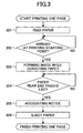
- Fig. 3 is a flowchart illustrating an accounting procedure in the image forming apparatus according to a first example of the present invention.
- One recording paper 30 is taken out from a feeding tray (not shown) and conveyed along a conveying way to the ink discharging unit 20 at Step 301.
- the image forming process starts.
- the printing starting point is normally provided in an image forming apparatus of printers or facsimile machines, in order to synchronize printing data reading and the image forming process.
- the image forming process is carried out while conveying the recording paper 30 at Step 303.
- a sensor 6b is provided to detect the existence of the recording paper 30.
- the sensor 6b is placed not at a paper ejecting point of the image forming apparatus, but at the exit of the ink discharging unit 20.
- the microcomputer 1 gives an accounting notice to the accounting unit 2 at Step 305.
- the recording paper 30 is still conveyed and finally ejected to an ejecting tray (not shown) at Step 306.
- a nonvolatile memory in the microcomputer 1 can store accounting contents.
- the microcomputer 1 can give an accounting notice to the accounting unit 2.
- the nonvolatile memory in the microcomputer 1 can store the accounting contents.
- Fig. 4 is a flowchart illustrating an accounting procedure in the image forming apparatus according to a second example of the present invention.
- the accounting is performed when the image formation is completed by detecting that the rear end of the recording paper 30 has passed the ink discharging unit 20.
- the accounting is performed when the image formation is started by detecting that the front end of the recording paper 30 has passed the ink discharging unit 20.
- One recording paper 30 is taken out from a feeding tray (not shown) and conveyed along a conveying way to the ink discharging unit 20 at Step 401.
- the image forming process starts.
- an entrance sensor 6a is provided to detect the existence of the recording paper 30.
- the microcomputer 1 gives an accounting notice to the accounting unit 2 at Step 404. After that the image forming process continues while conveying the recording paper 30 at Step 405.
- the recording paper 30 is still conveyed and finally ejected to an ejecting tray (not shown) at Step 406.
- the printing starting point is normally provided in an image forming apparatus of printers or facsimile machines, in order to synchronize printing data reading and the image forming process.
- the recording paper 30 does not necessarily pass the printing starting point before detection of the front end of the recording paper 30. Therefore, it may happen that the front end of the recording paper 30 is first detected, and then the recording paper 30 arrives at the printing starting point. In this case, Step 402 is carried out after the accounting notice at Step 404.
- the nonvolatile memory in the microcomputer 1 can store accounting contents.
- the microcomputer 1 can give an accounting notice to the accounting unit 2.
- the nonvolatile memory in the microcomputer 1 can store the accounting contents.
- Fig. 5 is a flowchart illustrating an accounting procedure in the image forming apparatus according to a third example of the present invention. In this example, it can be switched between the accounting being performed when the rear end of the recording paper 30 has passed the ink discharging unit 20 and the accounting being performed when the front end of the recording paper 30 has passed the ink discharging unit 20.
- the microcomputer 1 gives an accounting notice to the accounting unit 20 when the image formation is started (Steps 503, 504) or the image formation is completed (Steps 507, 508, 509) according to the switching condition stored in the microcomputer 2.
- the nonvolatile memory in the microcomputer 1 stores that the image formation has been started, and a first counter in the microcomputer increases its count value by one. And then the nonvolatile memory in the microcomputer 1 stores that the image formation has been completed, and a second counter in the microcomputer increases its count value by one.
- the accounting result is changed in accordance with the switching condition stored in the microcomputer 1.
- the first and second counters are normally equal to each other. If both the counter values exceed a threshold value, an abnormality may have occurred in the image forming apparatus, and the accounting may be improperly done. Under this situation, the accounting mode can be switched and it can be confirmed whether the accounting is properly done.
- the ink discharging unit 20 comprises a head having arrayed nozzles
- an image is formed by scanning the head over the recording paper 30.
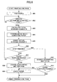
- the recording paper 30 arrives at the printing starting point at Step 602.
- the number N of total scanning passes required for forming a one-page image is calculated by analyzing the image data at Step 603.
- the microcomputer 1 may be a calculator.
- a counter in the microcomputer increases its count value by one at Step 605. If an instruction is given to stop the image forming process during the printing of the page, after printing the page, the total scanning number N and the actual scanning number C are compared to each other.
- the amount of the predetermined accounting unit multiplied by (the actual scanning number C) / (the total scanning number N) is charged at 610.
- the predetermined accounting unit is fully charged.
- the predetermined accounting unit multiplied by the actual scanning number is charged. In this manner, even if the image forming is stopped during the course of printing a page, the exact accounting can be performed.
- the accounting amount for one page is adjusted based on a head scanning rate.
- the accounting amount for one page is adjusted based on a recording paper conveying length.
- the recording paper 30 arrives at the printing starting point at Step 702.
- a recording paper conveying length L is calculated by the microcomputer 1 by analyzing the image data at Step 703.
- the actual length C of conveyed recording paper 30 is detected at Step 705. This is equal to the detection of the actual printing length. If the printing is stopped before the last data are printed, the accounting unit per page multiplied by (the actual printed length C) / (calculated recording paper length L) is charged at Step 710. In this manner, even if the image forming is stopped during the course of printing a page, the exact accounting can be performed.
Landscapes
- Physics & Mathematics (AREA)
- General Physics & Mathematics (AREA)
- Accessory Devices And Overall Control Thereof (AREA)
- Ink Jet (AREA)
Applications Claiming Priority (2)
| Application Number | Priority Date | Filing Date | Title |
|---|---|---|---|
| JP2004023466A JP2005212349A (ja) | 2004-01-30 | 2004-01-30 | 課金方法および画像形成装置 |
| JP2004023466 | 2004-01-30 |
Publications (2)
| Publication Number | Publication Date |
|---|---|
| EP1560081A1 true EP1560081A1 (de) | 2005-08-03 |
| EP1560081B1 EP1560081B1 (de) | 2008-08-20 |
Family
ID=34650850
Family Applications (1)
| Application Number | Title | Priority Date | Filing Date |
|---|---|---|---|
| EP05250490A Expired - Lifetime EP1560081B1 (de) | 2004-01-30 | 2005-01-31 | Drucker und Verfahren zur Benutzungsmessung |
Country Status (4)
| Country | Link |
|---|---|
| US (1) | US20080159767A1 (de) |
| EP (1) | EP1560081B1 (de) |
| JP (1) | JP2005212349A (de) |
| DE (1) | DE602005009040D1 (de) |
Cited By (1)
| Publication number | Priority date | Publication date | Assignee | Title |
|---|---|---|---|---|
| US8582988B2 (en) | 2010-09-27 | 2013-11-12 | Eastman Kodak Company | Effectively using a consumable in two printers |
Families Citing this family (2)
| Publication number | Priority date | Publication date | Assignee | Title |
|---|---|---|---|---|
| JP6140571B2 (ja) * | 2013-08-20 | 2017-05-31 | シャープ株式会社 | 画像形成装置 |
| JP7314692B2 (ja) * | 2019-07-31 | 2023-07-26 | コニカミノルタ株式会社 | 画像形成装置および画像形成装置診断システム |
Citations (7)
| Publication number | Priority date | Publication date | Assignee | Title |
|---|---|---|---|---|
| US3989930A (en) * | 1973-08-31 | 1976-11-02 | Xerox Corporation | Multi-mode billing system controlled by copy size and document original size |
| US4383756A (en) * | 1981-06-04 | 1983-05-17 | Minolta Camera Kabushiki Kaisha | Counter control in electrophotographic copier |
| EP0647532A1 (de) * | 1993-10-05 | 1995-04-12 | Riso Kagaku Corporation | Vorrichtung zum Vervielfältigen von Bildern |
| US5878298A (en) * | 1996-08-09 | 1999-03-02 | Canon Kabushiki Kaisha | Image forming apparatus mounting exchange unit with memory |
| JPH11272350A (ja) | 1998-03-20 | 1999-10-08 | Canon Inc | 課金管理装置及び方法及び印刷装置 |
| EP0996041A2 (de) * | 1998-10-23 | 2000-04-26 | Hewlett-Packard Company | Verfahren und Gerät zur Messung der Benutzung eines Druckers oder eines Kopiergeräts |
| US20030191655A1 (en) * | 2002-04-08 | 2003-10-09 | Janz Susan M. | Method and data processing system for a pay-for-usage print service |
Family Cites Families (5)
| Publication number | Priority date | Publication date | Assignee | Title |
|---|---|---|---|---|
| US5321467A (en) * | 1991-05-07 | 1994-06-14 | Canon Kabushiki Kaisha | Image forming apparatus with ink jet and electrophotographic recording units |
| JP4121209B2 (ja) * | 1999-02-26 | 2008-07-23 | 東北リコー株式会社 | 画像形成装置における給紙装置 |
| JP2001010178A (ja) * | 1999-06-30 | 2001-01-16 | Canon Aptex Inc | 記録制御装置および記録制御方法およびコンピュータが読み出し可能なプログラムを格納した記憶媒体 |
| JP2001177680A (ja) * | 1999-12-17 | 2001-06-29 | Canon Inc | 印刷装置、印刷装置での課金方法、及びコンピュータ読み取り可能な記憶媒体 |
| JP4068859B2 (ja) * | 2002-02-28 | 2008-03-26 | 理想科学工業株式会社 | 課金装置 |
-
2004
- 2004-01-30 JP JP2004023466A patent/JP2005212349A/ja active Pending
-
2005
- 2005-01-28 US US11/044,562 patent/US20080159767A1/en not_active Abandoned
- 2005-01-31 DE DE602005009040T patent/DE602005009040D1/de not_active Expired - Lifetime
- 2005-01-31 EP EP05250490A patent/EP1560081B1/de not_active Expired - Lifetime
Patent Citations (7)
| Publication number | Priority date | Publication date | Assignee | Title |
|---|---|---|---|---|
| US3989930A (en) * | 1973-08-31 | 1976-11-02 | Xerox Corporation | Multi-mode billing system controlled by copy size and document original size |
| US4383756A (en) * | 1981-06-04 | 1983-05-17 | Minolta Camera Kabushiki Kaisha | Counter control in electrophotographic copier |
| EP0647532A1 (de) * | 1993-10-05 | 1995-04-12 | Riso Kagaku Corporation | Vorrichtung zum Vervielfältigen von Bildern |
| US5878298A (en) * | 1996-08-09 | 1999-03-02 | Canon Kabushiki Kaisha | Image forming apparatus mounting exchange unit with memory |
| JPH11272350A (ja) | 1998-03-20 | 1999-10-08 | Canon Inc | 課金管理装置及び方法及び印刷装置 |
| EP0996041A2 (de) * | 1998-10-23 | 2000-04-26 | Hewlett-Packard Company | Verfahren und Gerät zur Messung der Benutzung eines Druckers oder eines Kopiergeräts |
| US20030191655A1 (en) * | 2002-04-08 | 2003-10-09 | Janz Susan M. | Method and data processing system for a pay-for-usage print service |
Cited By (1)
| Publication number | Priority date | Publication date | Assignee | Title |
|---|---|---|---|---|
| US8582988B2 (en) | 2010-09-27 | 2013-11-12 | Eastman Kodak Company | Effectively using a consumable in two printers |
Also Published As
| Publication number | Publication date |
|---|---|
| US20080159767A1 (en) | 2008-07-03 |
| JP2005212349A (ja) | 2005-08-11 |
| DE602005009040D1 (de) | 2008-10-02 |
| EP1560081B1 (de) | 2008-08-20 |
Similar Documents
| Publication | Publication Date | Title |
|---|---|---|
| US10782642B2 (en) | Image forming apparatus, image forming system, management apparatus, and non-transitory computer readable recording medium storing program | |
| JP3791127B2 (ja) | ファクシミリ装置 | |
| CN103057265B (zh) | 打印设备 | |
| CN104417056B (zh) | 打印装置和对打印位置移位进行校正的方法 | |
| US8672324B2 (en) | Printing apparatus and printed-material processing apparatus | |
| US6511239B1 (en) | Flyer determination and elimination for side edge electronic registration | |
| US20090225126A1 (en) | Image forming apparatus and storage medium storing diagnostic program used therewith | |
| US20180164712A1 (en) | Sheet processing apparatus for determining likelihood of sheets to stick after stacking | |
| EP1560081B1 (de) | Drucker und Verfahren zur Benutzungsmessung | |
| JP7102971B2 (ja) | 画像形成装置、管理装置およびプログラム | |
| EP0693717A1 (de) | Papierzufuhrsteuersystem für eine Druckeinheit | |
| CN101359198B (zh) | 图像形成设备 | |
| EP2085237B1 (de) | Bildgebungsvorrichtung, Transportsteuerverfahren und computerlesbares Aufzeichnungsmedium | |
| JP2004160797A (ja) | 記録装置 | |
| KR100548131B1 (ko) | 화상형성기기의 인쇄방법 | |
| CN103568563B (zh) | 打印设备和检查方法 | |
| JP2012101427A (ja) | 画像記録装置、及び画像記録装置の制御方法 | |
| US5850236A (en) | Prefiring method for an ink-jet head and apparatus having the ink-jet head with the prefiring method | |
| JP2021133609A (ja) | 画像形成装置 | |
| US9004626B2 (en) | Recording device, method of controlling a recording device, and a program | |
| US20230168618A1 (en) | Image forming apparatus | |
| JP2003140410A (ja) | 画像形成装置 | |
| JP2000321828A (ja) | 原稿給紙装置 | |
| JP3675382B2 (ja) | 画像形成装置 | |
| JP3983630B2 (ja) | インクレベル検知装置及びそのインクレベル検知装置を備えたインクジェット画像形成機 |
Legal Events
| Date | Code | Title | Description |
|---|---|---|---|
| PUAI | Public reference made under article 153(3) epc to a published international application that has entered the european phase |
Free format text: ORIGINAL CODE: 0009012 |
|
| 17P | Request for examination filed |
Effective date: 20050210 |
|
| AK | Designated contracting states |
Kind code of ref document: A1 Designated state(s): AT BE BG CH CY CZ DE DK EE ES FI FR GB GR HU IE IS IT LI LT LU MC NL PL PT RO SE SI SK TR |
|
| AX | Request for extension of the european patent |
Extension state: AL BA HR LV MK YU |
|
| AKX | Designation fees paid |
Designated state(s): DE FR GB |
|
| GRAP | Despatch of communication of intention to grant a patent |
Free format text: ORIGINAL CODE: EPIDOSNIGR1 |
|
| GRAS | Grant fee paid |
Free format text: ORIGINAL CODE: EPIDOSNIGR3 |
|
| GRAA | (expected) grant |
Free format text: ORIGINAL CODE: 0009210 |
|
| AK | Designated contracting states |
Kind code of ref document: B1 Designated state(s): DE FR GB |
|
| REG | Reference to a national code |
Ref country code: GB Ref legal event code: FG4D |
|
| REF | Corresponds to: |
Ref document number: 602005009040 Country of ref document: DE Date of ref document: 20081002 Kind code of ref document: P |
|
| PLBE | No opposition filed within time limit |
Free format text: ORIGINAL CODE: 0009261 |
|
| STAA | Information on the status of an ep patent application or granted ep patent |
Free format text: STATUS: NO OPPOSITION FILED WITHIN TIME LIMIT |
|
| 26N | No opposition filed |
Effective date: 20090525 |
|
| PGFP | Annual fee paid to national office [announced via postgrant information from national office to epo] |
Ref country code: DE Payment date: 20140122 Year of fee payment: 10 |
|
| PGFP | Annual fee paid to national office [announced via postgrant information from national office to epo] |
Ref country code: FR Payment date: 20140123 Year of fee payment: 10 |
|
| PGFP | Annual fee paid to national office [announced via postgrant information from national office to epo] |
Ref country code: GB Payment date: 20140121 Year of fee payment: 10 |
|
| REG | Reference to a national code |
Ref country code: DE Ref legal event code: R119 Ref document number: 602005009040 Country of ref document: DE |
|
| GBPC | Gb: european patent ceased through non-payment of renewal fee |
Effective date: 20150131 |
|
| PG25 | Lapsed in a contracting state [announced via postgrant information from national office to epo] |
Ref country code: DE Free format text: LAPSE BECAUSE OF NON-PAYMENT OF DUE FEES Effective date: 20150801 Ref country code: GB Free format text: LAPSE BECAUSE OF NON-PAYMENT OF DUE FEES Effective date: 20150131 |
|
| REG | Reference to a national code |
Ref country code: FR Ref legal event code: ST Effective date: 20150930 |
|
| PG25 | Lapsed in a contracting state [announced via postgrant information from national office to epo] |
Ref country code: FR Free format text: LAPSE BECAUSE OF NON-PAYMENT OF DUE FEES Effective date: 20150202 |