EP1560035A1 - Vorrichtung zur Erzeugung eines Magnetfeldes - Google Patents
Vorrichtung zur Erzeugung eines Magnetfeldes Download PDFInfo
- Publication number
- EP1560035A1 EP1560035A1 EP04256751A EP04256751A EP1560035A1 EP 1560035 A1 EP1560035 A1 EP 1560035A1 EP 04256751 A EP04256751 A EP 04256751A EP 04256751 A EP04256751 A EP 04256751A EP 1560035 A1 EP1560035 A1 EP 1560035A1
- Authority
- EP
- European Patent Office
- Prior art keywords
- refrigerator
- assembly according
- coolant
- coolant path
- cooling
- Prior art date
- Legal status (The legal status is an assumption and is not a legal conclusion. Google has not performed a legal analysis and makes no representation as to the accuracy of the status listed.)
- Granted
Links
- 239000002826 coolant Substances 0.000 claims abstract description 42
- 238000001816 cooling Methods 0.000 claims abstract description 39
- 239000000523 sample Substances 0.000 claims description 23
- 230000008878 coupling Effects 0.000 claims description 2
- 238000010168 coupling process Methods 0.000 claims description 2
- 238000005859 coupling reaction Methods 0.000 claims description 2
- 238000001704 evaporation Methods 0.000 claims description 2
- 239000007789 gas Substances 0.000 description 19
- 230000000694 effects Effects 0.000 description 6
- 239000001307 helium Substances 0.000 description 6
- 229910052734 helium Inorganic materials 0.000 description 6
- SWQJXJOGLNCZEY-UHFFFAOYSA-N helium atom Chemical compound [He] SWQJXJOGLNCZEY-UHFFFAOYSA-N 0.000 description 6
- 239000007788 liquid Substances 0.000 description 3
- XKRFYHLGVUSROY-UHFFFAOYSA-N Argon Chemical compound [Ar] XKRFYHLGVUSROY-UHFFFAOYSA-N 0.000 description 2
- IJGRMHOSHXDMSA-UHFFFAOYSA-N Atomic nitrogen Chemical compound N#N IJGRMHOSHXDMSA-UHFFFAOYSA-N 0.000 description 2
- 230000000712 assembly Effects 0.000 description 2
- 238000000429 assembly Methods 0.000 description 2
- 238000012512 characterization method Methods 0.000 description 2
- 238000010586 diagram Methods 0.000 description 2
- 239000000463 material Substances 0.000 description 2
- 238000005259 measurement Methods 0.000 description 2
- 230000005855 radiation Effects 0.000 description 2
- RYGMFSIKBFXOCR-UHFFFAOYSA-N Copper Chemical compound [Cu] RYGMFSIKBFXOCR-UHFFFAOYSA-N 0.000 description 1
- 229910052786 argon Inorganic materials 0.000 description 1
- 238000010276 construction Methods 0.000 description 1
- 238000011109 contamination Methods 0.000 description 1
- 229910052802 copper Inorganic materials 0.000 description 1
- 239000010949 copper Substances 0.000 description 1
- 238000005516 engineering process Methods 0.000 description 1
- 229910052757 nitrogen Inorganic materials 0.000 description 1
- 238000005057 refrigeration Methods 0.000 description 1
- 229910001220 stainless steel Inorganic materials 0.000 description 1
- 239000010935 stainless steel Substances 0.000 description 1
- 229910052724 xenon Inorganic materials 0.000 description 1
- FHNFHKCVQCLJFQ-UHFFFAOYSA-N xenon atom Chemical compound [Xe] FHNFHKCVQCLJFQ-UHFFFAOYSA-N 0.000 description 1
Images


Classifications
-
- F—MECHANICAL ENGINEERING; LIGHTING; HEATING; WEAPONS; BLASTING
- F25—REFRIGERATION OR COOLING; COMBINED HEATING AND REFRIGERATION SYSTEMS; HEAT PUMP SYSTEMS; MANUFACTURE OR STORAGE OF ICE; LIQUEFACTION SOLIDIFICATION OF GASES
- F25D—REFRIGERATORS; COLD ROOMS; ICE-BOXES; COOLING OR FREEZING APPARATUS NOT OTHERWISE PROVIDED FOR
- F25D19/00—Arrangement or mounting of refrigeration units with respect to devices or objects to be refrigerated, e.g. infrared detectors
-
- G—PHYSICS
- G01—MEASURING; TESTING
- G01R—MEASURING ELECTRIC VARIABLES; MEASURING MAGNETIC VARIABLES
- G01R33/00—Arrangements or instruments for measuring magnetic variables
- G01R33/20—Arrangements or instruments for measuring magnetic variables involving magnetic resonance
- G01R33/28—Details of apparatus provided for in groups G01R33/44 - G01R33/64
- G01R33/38—Systems for generation, homogenisation or stabilisation of the main or gradient magnetic field
- G01R33/381—Systems for generation, homogenisation or stabilisation of the main or gradient magnetic field using electromagnets
- G01R33/3815—Systems for generation, homogenisation or stabilisation of the main or gradient magnetic field using electromagnets with superconducting coils, e.g. power supply therefor
-
- F—MECHANICAL ENGINEERING; LIGHTING; HEATING; WEAPONS; BLASTING
- F25—REFRIGERATION OR COOLING; COMBINED HEATING AND REFRIGERATION SYSTEMS; HEAT PUMP SYSTEMS; MANUFACTURE OR STORAGE OF ICE; LIQUEFACTION SOLIDIFICATION OF GASES
- F25B—REFRIGERATION MACHINES, PLANTS OR SYSTEMS; COMBINED HEATING AND REFRIGERATION SYSTEMS; HEAT PUMP SYSTEMS
- F25B9/00—Compression machines, plants or systems, in which the refrigerant is air or other gas of low boiling point
- F25B9/10—Compression machines, plants or systems, in which the refrigerant is air or other gas of low boiling point with several cooling stages
-
- F—MECHANICAL ENGINEERING; LIGHTING; HEATING; WEAPONS; BLASTING
- F25—REFRIGERATION OR COOLING; COMBINED HEATING AND REFRIGERATION SYSTEMS; HEAT PUMP SYSTEMS; MANUFACTURE OR STORAGE OF ICE; LIQUEFACTION SOLIDIFICATION OF GASES
- F25B—REFRIGERATION MACHINES, PLANTS OR SYSTEMS; COMBINED HEATING AND REFRIGERATION SYSTEMS; HEAT PUMP SYSTEMS
- F25B9/00—Compression machines, plants or systems, in which the refrigerant is air or other gas of low boiling point
- F25B9/14—Compression machines, plants or systems, in which the refrigerant is air or other gas of low boiling point characterised by the cycle used, e.g. Stirling cycle
- F25B9/145—Compression machines, plants or systems, in which the refrigerant is air or other gas of low boiling point characterised by the cycle used, e.g. Stirling cycle pulse-tube cycle
-
- F—MECHANICAL ENGINEERING; LIGHTING; HEATING; WEAPONS; BLASTING
- F25—REFRIGERATION OR COOLING; COMBINED HEATING AND REFRIGERATION SYSTEMS; HEAT PUMP SYSTEMS; MANUFACTURE OR STORAGE OF ICE; LIQUEFACTION SOLIDIFICATION OF GASES
- F25D—REFRIGERATORS; COLD ROOMS; ICE-BOXES; COOLING OR FREEZING APPARATUS NOT OTHERWISE PROVIDED FOR
- F25D19/00—Arrangement or mounting of refrigeration units with respect to devices or objects to be refrigerated, e.g. infrared detectors
- F25D19/006—Thermal coupling structure or interface
Definitions
- the invention relates to a magnetic field generating assembly comprising a superconducting magnet located in a cryostat and defining a bore accessible from outside the cryostat.
- a magnetic field generating assembly comprising a superconducting magnet located in a cryostat and defining a bore accessible from outside the cryostat.
- Such assemblies are used in a wide variety of applications including NMR, MRI and FTICR.
- the invention is also applicable to other measurement devices requiring low temperatures such as those for material characterisation.
- Typical cryostats include a number of radiation heat shields together with a coolant, such as liquid helium, within which the superconducting magnet is located.
- a sample or components such as RF and/or gradient coils are located in the bore, typically at room temperature, and in the case of components may be permanently mounted within the bore or mounted on a removable probe.
- RF and/or gradient coils are located in the bore, typically at room temperature, and in the case of components may be permanently mounted within the bore or mounted on a removable probe.
- cryocooler designed for an MRI probe
- Wang et al paper presented at CEC-ICMC, Sept. 22-26, 2003, Anchorage, Alaska, USA.
- the components could be located within the cryostat (but cooled by a separate coolant path) as described in WO 03/023433.
- this is not always possible since it is difficult to change the components once they are located in the cryostat.
- it will not always be possible to obtain sufficient cooling power.
- a magnetic field generating assembly comprises a superconducting magnet located in a cryostat and defining a bore accessible from outside the cryostat; and a mechanical refrigerator having at least two cooling stages for at least partly cooling the cryostat; and a coolant path extending from the refrigerator into the magnet bore, the coolant path being coupled for heat exchange with a cooling stage of the refrigerator other than the coldest cooling stage so that the refrigerator is adapted also to cool coolant in the coolant path.
- the remaining cooling effect is not enough to cool extra circuit gas in the coolant path to 4 K and also the cooling effect available for the probe would be now less than 0.5 watts only which is not sufficient.
- the cooling effect requirement for a NMR probe is around 2-5 W at around 20-25 K. In order to make this possible the cooling effect has to be drawn from an intermediate stage only and not the coldest stage.
- the coolant path is used to cool components which are permanently mounted in the bore including RF and/or gradient coils.
- the coolant path can be used to cool components and/or a sample mounted on a probe which is insertable into and removable from the bore.
- at least part of the coolant path is preferably formed from a flexible conduit.
- the number of stages will depend on the temperature requirement for the bore. If the shield temperature and the coil temperature match the refrigeration capacities available then two stages could be enough. This could be true for some applications if the coil temperature requirements are around 40-50K and the first stage of the refrigerator can cool the probe electronics/sample. However, for NMR, if the coil temperature requirement is around 20-30K then an additional, intermediate stage, at 15-20K would be needed for cooling the coolant path.
- a three (or more) stage refrigerator allows more flexibility in the applications with which the assembly can be used e.g. MRI, NMR and FTICR, when the temperature requirement of the probe can differ.
- a 2 stage refrigerator cannot do that as its 2 stage temperatures are fixed - one for radiation shield and the other for recondensing, unless the shield and coil temperature match. This technology could also be used in conjunction with other measurement devices requiring low temperatures such as those for material characterisation.
- one or more stages of the refrigerator will be coupled to a corresponding number of heat shields of the cryostat, for example to 45-50 K.
- the coolant path may be coupled to one or more of the cooling stages also.
- one of the cooling stages of the refrigerator may be used solely for cooling the coolant path while the other(s) is used for cooling the cryostat.
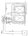
- FIG. 1 The example shown in Figure 1 comprises a cryostat 1 defined by an outer vacuum chamber 2 with an upwardly extending neck 3. Within the chamber 2 is located a cooled shield 4 surrounding a liquid helium vessel 5 in which is located a superconducting magnet 6. The magnet 6 surrounds a bore 7 which is located outside the cryostat at room temperature.
- a cryocooler in the form of three stage pulse tube refrigerator (PTR) 10 (not shown) is mounted within a three stage sack in the neck 3 of the cryostat.
- PTR pulse tube refrigerator
- the three stages of the refrigerator 10 are indicated at 11-13.
- the first stage 11 is held at a temperature of about 50K, the second stage at a temperature in the range 20-25K, and the third stage at a temperature of about 4.2K.
- the first stage 11 is coupled via flexible braid connections 14 to the shield 4 so as to hold the temperature of the shield at about 50K.
- the third stage 13 is located in the liquid helium vessel 5 and will re-condense evaporating helium.
- the PTR 10 is connected to a gas compressor 15 which supplies compressed gas typically Helium although other gases such as argon, nitrogen, xenon etc. could be used, along a supply line 16 to a high pressure inlet 17 of the PTR 10.
- This compressed gas is used to cool the stages 11-13 in a conventional manner and gas then returns along a return line 18 to the compressor 15.
- a suitable PTR is described in "Novel configuration of three-stage pulse tube refrigerator for temperatures below 4K", Matsubara et al, Cryogenics 1994, Vol. 34, No. 4, pages 259-262.
- Alternative refrigerators which could be used are Stirling, Gifford-McMahon and Joule-Thomson refrigerators.
- a small proportion of the compressed gas from the supply line 16 is tapped off via a valve 20 and fed via a gas purifier 21 to a heat exchanger 22.
- the heat exchanger 22 pre-cools the incoming compressed gas (as explained below) which is then supplied into the neck 3 of the cryostat as can be seen more clearly in Figure 3.
- This gas passes along a conduit 23 until it reaches the first stage 11 of the PTR 10 and then is fed on to the second stage 12 before returning along a conduit 24.
- the gas has thus been cooled to 20-25K.
- the gas is then supplied along a conduit 25 to a probe 26.
- the probe 26 carries typically a sample and/or RF and/or gradient coils and can be removably inserted into the bore 7 as shown.
- the cooled gas in the conduit 25 is thus used to cool the components and/or sample on or in the probe 26 and then returns along a return line 27 to the heat exchanger 22 where it assists in pre-cooling the incoming compressed gas.
- the returning gas is then returned to the return line 18 coupled to the compressor 15.
- conduit 25 and return line 27 in the form of capillaries are provided in a convoluted copper sleeve (not shown) and this in turn is located in a flexible stainless steel pipe (also not shown).
- the cooling system will consist of small capillary tubes (not shown) and thus it is important to provide the gas purifier 21 to prevent contamination or moisture in the gas which could block the capillary tubes and thus stop the flow.
- FIG. 2 An alternative approach to avoiding this problem is shown in Figure 2.
- the structure of Figure 2 is the same as that shown in Figure 1 except that the coolant circuit to the probe 26 is completely separate from the compressed gas circuit of the PTR 10.
- a further dry compressor or pump 30 is provided coupled to the supply and return lines 25,27 of the coolant path to the probe 26.
Landscapes
- Physics & Mathematics (AREA)
- Engineering & Computer Science (AREA)
- Chemical & Material Sciences (AREA)
- Combustion & Propulsion (AREA)
- Mechanical Engineering (AREA)
- Thermal Sciences (AREA)
- General Engineering & Computer Science (AREA)
- Electromagnetism (AREA)
- Condensed Matter Physics & Semiconductors (AREA)
- General Physics & Mathematics (AREA)
- Magnetic Resonance Imaging Apparatus (AREA)
- Containers, Films, And Cooling For Superconductive Devices (AREA)
Applications Claiming Priority (2)
| Application Number | Priority Date | Filing Date | Title |
|---|---|---|---|
| GB0401835 | 2004-01-28 | ||
| GBGB0401835.4A GB0401835D0 (en) | 2004-01-28 | 2004-01-28 | Magnetic field generating assembly |
Publications (2)
| Publication Number | Publication Date |
|---|---|
| EP1560035A1 true EP1560035A1 (de) | 2005-08-03 |
| EP1560035B1 EP1560035B1 (de) | 2007-08-29 |
Family
ID=31971588
Family Applications (1)
| Application Number | Title | Priority Date | Filing Date |
|---|---|---|---|
| EP04256751A Not-in-force EP1560035B1 (de) | 2004-01-28 | 2004-11-02 | Vorrichtung zur Erzeugung eines Magnetfeldes |
Country Status (6)
| Country | Link |
|---|---|
| US (1) | US7191601B2 (de) |
| EP (1) | EP1560035B1 (de) |
| JP (1) | JP2005214976A (de) |
| CN (1) | CN1649041A (de) |
| DE (1) | DE602004008572T2 (de) |
| GB (1) | GB0401835D0 (de) |
Cited By (6)
| Publication number | Priority date | Publication date | Assignee | Title |
|---|---|---|---|---|
| GB2422422A (en) * | 2004-12-17 | 2006-07-26 | Bruker Biospin Gmbh | NMR spectrometer with common refrigerator for cooling an NMR probe head and cryostat |
| EP1760480A1 (de) * | 2005-09-01 | 2007-03-07 | Bruker BioSpin AG | NMR-Apparatur mit gemeinsam gekühltem Probenkopf und Kryobehälter |
| GB2433581A (en) * | 2005-12-22 | 2007-06-27 | Siemens Magnet Technology Ltd | Closed-loop pre-cooling of cryogenically cooled equipment |
| US7430871B2 (en) | 2004-11-09 | 2008-10-07 | Bruker Biospin Gmbh | NMR spectrometer with a common refrigerator for cooling an NMR probe head and cryostat |
| EP1628109A3 (de) * | 2004-07-30 | 2009-03-25 | Bruker BioSpin AG | Kryostatanordnung |
| WO2021156103A1 (de) * | 2020-02-07 | 2021-08-12 | Bruker Switzerland Ag | Nmr-messanordnung mit kalter bohrung des kryostaten |
Families Citing this family (23)
| Publication number | Priority date | Publication date | Assignee | Title |
|---|---|---|---|---|
| US7484372B2 (en) * | 2006-03-06 | 2009-02-03 | Linde, Inc. | Multi-bath apparatus and method for cooling superconductors |
| GB2443674B (en) * | 2006-10-04 | 2008-11-26 | Oxford Instr Superconductivity | Flow-cooled magnet system |
| US7631507B2 (en) * | 2006-11-02 | 2009-12-15 | General Electric Company | Methods and devices for polarized samples for use in MRI |
| US8375742B2 (en) * | 2007-08-21 | 2013-02-19 | Cryomech, Inc. | Reliquifier and recondenser with vacuum insulated sleeve and liquid transfer tube |
| US20090049862A1 (en) * | 2007-08-21 | 2009-02-26 | Cryomech, Inc. | Reliquifier |
| US7646272B1 (en) * | 2007-10-12 | 2010-01-12 | The United States Of America As Represented By The United States Department Of Energy | Freely oriented portable superconducting magnet |
| US20100267567A1 (en) * | 2007-12-10 | 2010-10-21 | Koninklijke Philips Electronics N.V. | Superconducting magnet system with cooling system |
| EP2519786B1 (de) * | 2009-12-28 | 2019-03-27 | Koninklijke Philips N.V. | Kryokühlersystem mit einem rohrförmigen wärmeschutzschalter |
| US20110173996A1 (en) * | 2010-01-20 | 2011-07-21 | Mark Glajchen | Methods for recovering helium |
| US9234691B2 (en) * | 2010-03-11 | 2016-01-12 | Quantum Design International, Inc. | Method and apparatus for controlling temperature in a cryocooled cryostat using static and moving gas |
| US8710944B2 (en) * | 2010-05-25 | 2014-04-29 | General Electric Company | Superconducting magnetizer |
| DE102011005888B4 (de) * | 2011-03-22 | 2014-01-09 | Bruker Biospin Ag | Kühlung eines Kryo-Probenkopfes in einer Kernspinresonanz-Apparatur |
| US20130186110A1 (en) * | 2011-07-14 | 2013-07-25 | Sastry Pamidi | Auxiliary Cryogenic Cooling Systems Based on Commercial Cryo-Coolers |
| GB201212800D0 (en) * | 2012-07-19 | 2012-09-05 | Oxford Instr Nanotechnology Tools Ltd | Cryogenic cooloing apparatus and method |
| FR3000555B1 (fr) * | 2012-12-27 | 2016-02-19 | Commissariat Energie Atomique | Dispositf d'analyse par resonnance magnetique nucleaire et procede de fonctionnement du dispositif |
| CN103077797B (zh) * | 2013-01-06 | 2016-03-30 | 中国科学院电工研究所 | 用于头部成像的超导磁体系统 |
| CN104188725B (zh) * | 2014-08-26 | 2016-08-24 | 中国科学院电工研究所 | 一种心脏磁导航手术系统的磁场发生装置 |
| WO2016163021A1 (ja) * | 2015-04-10 | 2016-10-13 | 三菱電機株式会社 | 超電導マグネット |
| JP6626816B2 (ja) * | 2016-11-24 | 2019-12-25 | ジャパンスーパーコンダクタテクノロジー株式会社 | 超電導コイルの予冷方法及び超電導マグネット装置 |
| GB2566024B (en) * | 2017-08-30 | 2020-08-12 | Siemens Healthcare Ltd | A Fault-Tolerant Cryogenically Cooled System |
| US11009572B2 (en) * | 2018-09-24 | 2021-05-18 | Shahin Pourrahimi | Integrated single-sourced cooling of superconducting magnets and RF coils in nuclear magnetic resonance devices |
| CN109712783B (zh) * | 2019-01-15 | 2020-12-11 | 娄莉 | 一种mri冷却装置 |
| US11630172B2 (en) * | 2021-03-15 | 2023-04-18 | Bruker Biospin Corp. | NMR magnet system with Stirling cooler |
Citations (2)
| Publication number | Priority date | Publication date | Assignee | Title |
|---|---|---|---|---|
| WO2003023433A1 (en) * | 2001-09-06 | 2003-03-20 | Oxford Instruments Superconductivity Limited | Apparatus for use in nmr system |
| US6629418B1 (en) * | 2002-01-08 | 2003-10-07 | Shi-Apd Cryogenics, Inc. | Two-stage inter-phasing pulse tube refrigerators with and without shared buffer volumes |
Family Cites Families (5)
| Publication number | Priority date | Publication date | Assignee | Title |
|---|---|---|---|---|
| US5485730A (en) * | 1994-08-10 | 1996-01-23 | General Electric Company | Remote cooling system for a superconducting magnet |
| US5513498A (en) * | 1995-04-06 | 1996-05-07 | General Electric Company | Cryogenic cooling system |
| DE10104365C1 (de) * | 2001-02-01 | 2002-08-22 | Bruker Biospin Gmbh | Supraleitendes Magnetsystem und magnetisches Resonanzspektrometer sowie Verfahre zu dessen Betrieb |
| US6415613B1 (en) * | 2001-03-16 | 2002-07-09 | General Electric Company | Cryogenic cooling system with cooldown and normal modes of operation |
| US6640552B1 (en) * | 2002-09-26 | 2003-11-04 | Praxair Technology, Inc. | Cryogenic superconductor cooling system |
-
2004
- 2004-01-28 GB GBGB0401835.4A patent/GB0401835D0/en not_active Ceased
- 2004-10-08 US US10/960,280 patent/US7191601B2/en not_active Expired - Fee Related
- 2004-11-02 EP EP04256751A patent/EP1560035B1/de not_active Not-in-force
- 2004-11-02 DE DE602004008572T patent/DE602004008572T2/de not_active Expired - Fee Related
- 2004-12-28 CN CN200410081743.2A patent/CN1649041A/zh active Pending
-
2005
- 2005-01-28 JP JP2005020609A patent/JP2005214976A/ja active Pending
Patent Citations (2)
| Publication number | Priority date | Publication date | Assignee | Title |
|---|---|---|---|---|
| WO2003023433A1 (en) * | 2001-09-06 | 2003-03-20 | Oxford Instruments Superconductivity Limited | Apparatus for use in nmr system |
| US6629418B1 (en) * | 2002-01-08 | 2003-10-07 | Shi-Apd Cryogenics, Inc. | Two-stage inter-phasing pulse tube refrigerators with and without shared buffer volumes |
Non-Patent Citations (1)
| Title |
|---|
| P.S. THOMPSON ET AL.: "A two-stage pulse tube cryo-cooled MRI magnet", AIP CONFERENCE PROCEEDINGS AIP USA, no. 613A, 2002, pages 649 - 653, XP008036029, ISSN: 0094-243X * |
Cited By (13)
| Publication number | Priority date | Publication date | Assignee | Title |
|---|---|---|---|---|
| EP1628109A3 (de) * | 2004-07-30 | 2009-03-25 | Bruker BioSpin AG | Kryostatanordnung |
| US7430871B2 (en) | 2004-11-09 | 2008-10-07 | Bruker Biospin Gmbh | NMR spectrometer with a common refrigerator for cooling an NMR probe head and cryostat |
| GB2422422B (en) * | 2004-12-17 | 2009-02-25 | Bruker Biospin Gmbh | NMR spectrometer with common refrigerator for cooling an NMR probe head and cryostat |
| US7430872B2 (en) | 2004-12-17 | 2008-10-07 | Bruker Biospin Gmbh | NMR spectrometer with common refrigerator for cooling an NMR probe head and cryostat |
| GB2422422A (en) * | 2004-12-17 | 2006-07-26 | Bruker Biospin Gmbh | NMR spectrometer with common refrigerator for cooling an NMR probe head and cryostat |
| DE102005041383B4 (de) * | 2005-09-01 | 2007-09-27 | Bruker Biospin Ag | NMR-Apparatur mit gemeinsam gekühltem Probenkopf und Kryobehälter und Verfahren zum Betrieb derselben |
| DE102005041383A1 (de) * | 2005-09-01 | 2007-03-22 | Bruker Biospin Ag | NMR-Apparatur mit gemeinsam gekühltem Probenkopf und Kryobehälter und Verfahren zum Betrieb derselben |
| US7474099B2 (en) | 2005-09-01 | 2009-01-06 | Bruker Biospin Ag | NMR apparatus with commonly cooled probe head and cryogenic container and method for the operation thereof |
| EP1760480A1 (de) * | 2005-09-01 | 2007-03-07 | Bruker BioSpin AG | NMR-Apparatur mit gemeinsam gekühltem Probenkopf und Kryobehälter |
| GB2433581A (en) * | 2005-12-22 | 2007-06-27 | Siemens Magnet Technology Ltd | Closed-loop pre-cooling of cryogenically cooled equipment |
| GB2433581B (en) * | 2005-12-22 | 2008-02-27 | Siemens Magnet Technology Ltd | Closed-loop precooling of cryogenically cooled equipment |
| WO2021156103A1 (de) * | 2020-02-07 | 2021-08-12 | Bruker Switzerland Ag | Nmr-messanordnung mit kalter bohrung des kryostaten |
| US11953570B2 (en) | 2020-02-07 | 2024-04-09 | Bruker Switzerland Ag | NMR measuring assembly with cold bore of the cryostat |
Also Published As
| Publication number | Publication date |
|---|---|
| DE602004008572D1 (de) | 2007-10-11 |
| EP1560035B1 (de) | 2007-08-29 |
| JP2005214976A (ja) | 2005-08-11 |
| US7191601B2 (en) | 2007-03-20 |
| DE602004008572T2 (de) | 2008-05-21 |
| US20050262851A1 (en) | 2005-12-01 |
| CN1649041A (zh) | 2005-08-03 |
| GB0401835D0 (en) | 2004-03-03 |
Similar Documents
| Publication | Publication Date | Title |
|---|---|---|
| EP1560035B1 (de) | Vorrichtung zur Erzeugung eines Magnetfeldes | |
| US5508613A (en) | Apparatus for cooling NMR coils | |
| US7430871B2 (en) | NMR spectrometer with a common refrigerator for cooling an NMR probe head and cryostat | |
| JP4336359B2 (ja) | 共通に冷却されるプローブヘッド及び低温容器を備えたnmr装置およびその動作方法 | |
| JP4352040B2 (ja) | 冷凍機冷却式nmr分光器 | |
| US5913888A (en) | Antenna device having at least one cooled antenna | |
| CN107705955B (zh) | 包括超导磁体组件和冷却取样头部件的nmr设备 | |
| EP1586833A2 (de) | Kühlvorrichtung | |
| US20050202976A1 (en) | Apparatus for use in nmr system | |
| US5193348A (en) | Device for cooling a squid measuring instrument | |
| JP2013522574A (ja) | 静止状態及び流動状態のガスを用いて超低温冷却クライオスタットにおける温度を制御するための方法およびその装置 | |
| WO2003036207A3 (en) | A pulse tube refrigeration with an insulating sleeve | |
| US20090275476A1 (en) | Cryostat assembly | |
| JP4275640B2 (ja) | 極低温冷却装置 | |
| US20090301129A1 (en) | Helium and nitrogen reliquefying apparatus | |
| JP3858269B2 (ja) | 冷却管及びこれを用いた極低温クライオスタット | |
| JP4150825B2 (ja) | Nmrプローブ | |
| US20220236349A1 (en) | Accelerated cooldown of low-cryogen magnetic resonance imaging (mri) magnets | |
| JP2007078310A (ja) | 極低温冷却装置 | |
| JPH02302680A (ja) | グラジオメータ冷却装置 | |
| JP2006189272A (ja) | 核磁気共鳴測定装置 | |
| Thummes et al. | Adaptive cooling on the basis of pulse tube refrigerators |
Legal Events
| Date | Code | Title | Description |
|---|---|---|---|
| PUAI | Public reference made under article 153(3) epc to a published international application that has entered the european phase |
Free format text: ORIGINAL CODE: 0009012 |
|
| 17P | Request for examination filed |
Effective date: 20041122 |
|
| AK | Designated contracting states |
Kind code of ref document: A1 Designated state(s): AT BE BG CH CY CZ DE DK EE ES FI FR GB GR HU IE IS IT LI LU MC NL PL PT RO SE SI SK TR |
|
| AX | Request for extension of the european patent |
Extension state: AL HR LT LV MK YU |
|
| AKX | Designation fees paid |
Designated state(s): CH DE FR GB IT LI NL |
|
| 17Q | First examination report despatched |
Effective date: 20060831 |
|
| GRAP | Despatch of communication of intention to grant a patent |
Free format text: ORIGINAL CODE: EPIDOSNIGR1 |
|
| GRAS | Grant fee paid |
Free format text: ORIGINAL CODE: EPIDOSNIGR3 |
|
| GRAA | (expected) grant |
Free format text: ORIGINAL CODE: 0009210 |
|
| AK | Designated contracting states |
Kind code of ref document: B1 Designated state(s): CH DE FR GB IT LI NL |
|
| REG | Reference to a national code |
Ref country code: GB Ref legal event code: FG4D |
|
| REG | Reference to a national code |
Ref country code: CH Ref legal event code: EP |
|
| REF | Corresponds to: |
Ref document number: 602004008572 Country of ref document: DE Date of ref document: 20071011 Kind code of ref document: P |
|
| ET | Fr: translation filed | ||
| PG25 | Lapsed in a contracting state [announced via postgrant information from national office to epo] |
Ref country code: NL Free format text: LAPSE BECAUSE OF FAILURE TO SUBMIT A TRANSLATION OF THE DESCRIPTION OR TO PAY THE FEE WITHIN THE PRESCRIBED TIME-LIMIT Effective date: 20070829 |
|
| NLV1 | Nl: lapsed or annulled due to failure to fulfill the requirements of art. 29p and 29m of the patents act | ||
| PG25 | Lapsed in a contracting state [announced via postgrant information from national office to epo] |
Ref country code: CH Free format text: LAPSE BECAUSE OF FAILURE TO SUBMIT A TRANSLATION OF THE DESCRIPTION OR TO PAY THE FEE WITHIN THE PRESCRIBED TIME-LIMIT Effective date: 20070829 Ref country code: LI Free format text: LAPSE BECAUSE OF FAILURE TO SUBMIT A TRANSLATION OF THE DESCRIPTION OR TO PAY THE FEE WITHIN THE PRESCRIBED TIME-LIMIT Effective date: 20070829 |
|
| REG | Reference to a national code |
Ref country code: CH Ref legal event code: PL |
|
| PLBE | No opposition filed within time limit |
Free format text: ORIGINAL CODE: 0009261 |
|
| STAA | Information on the status of an ep patent application or granted ep patent |
Free format text: STATUS: NO OPPOSITION FILED WITHIN TIME LIMIT |
|
| 26N | No opposition filed |
Effective date: 20080530 |
|
| PGFP | Annual fee paid to national office [announced via postgrant information from national office to epo] |
Ref country code: DE Payment date: 20081103 Year of fee payment: 5 |
|
| PGFP | Annual fee paid to national office [announced via postgrant information from national office to epo] |
Ref country code: FR Payment date: 20081112 Year of fee payment: 5 |
|
| PGFP | Annual fee paid to national office [announced via postgrant information from national office to epo] |
Ref country code: GB Payment date: 20081029 Year of fee payment: 5 |
|
| GBPC | Gb: european patent ceased through non-payment of renewal fee |
Effective date: 20091102 |
|
| REG | Reference to a national code |
Ref country code: FR Ref legal event code: ST Effective date: 20100730 |
|
| PG25 | Lapsed in a contracting state [announced via postgrant information from national office to epo] |
Ref country code: FR Free format text: LAPSE BECAUSE OF NON-PAYMENT OF DUE FEES Effective date: 20091130 |
|
| PG25 | Lapsed in a contracting state [announced via postgrant information from national office to epo] |
Ref country code: DE Free format text: LAPSE BECAUSE OF NON-PAYMENT OF DUE FEES Effective date: 20100601 |
|
| PG25 | Lapsed in a contracting state [announced via postgrant information from national office to epo] |
Ref country code: GB Free format text: LAPSE BECAUSE OF NON-PAYMENT OF DUE FEES Effective date: 20091102 |
|
| PG25 | Lapsed in a contracting state [announced via postgrant information from national office to epo] |
Ref country code: IT Free format text: LAPSE BECAUSE OF NON-PAYMENT OF DUE FEES Effective date: 20071130 |