EP1559846B1 - Deckenelemente und Anordnungen solcher Deckenelemente für abgehängte Decken - Google Patents
Deckenelemente und Anordnungen solcher Deckenelemente für abgehängte Decken Download PDFInfo
- Publication number
- EP1559846B1 EP1559846B1 EP04022999A EP04022999A EP1559846B1 EP 1559846 B1 EP1559846 B1 EP 1559846B1 EP 04022999 A EP04022999 A EP 04022999A EP 04022999 A EP04022999 A EP 04022999A EP 1559846 B1 EP1559846 B1 EP 1559846B1
- Authority
- EP
- European Patent Office
- Prior art keywords
- panels
- frame
- fabric
- slot
- panel according
- Prior art date
- Legal status (The legal status is an assumption and is not a legal conclusion. Google has not performed a legal analysis and makes no representation as to the accuracy of the status listed.)
- Expired - Lifetime
Links
- 239000004744 fabric Substances 0.000 claims description 78
- 239000000463 material Substances 0.000 claims description 25
- 239000000725 suspension Substances 0.000 claims description 20
- 238000006073 displacement reaction Methods 0.000 claims description 12
- 238000003780 insertion Methods 0.000 claims description 9
- 230000037431 insertion Effects 0.000 claims description 9
- 230000013011 mating Effects 0.000 claims description 6
- 125000006850 spacer group Chemical group 0.000 claims description 4
- 239000003365 glass fiber Substances 0.000 claims 1
- 238000009434 installation Methods 0.000 description 8
- 230000006835 compression Effects 0.000 description 3
- 238000007906 compression Methods 0.000 description 3
- 230000004048 modification Effects 0.000 description 3
- 238000012986 modification Methods 0.000 description 3
- 239000007787 solid Substances 0.000 description 3
- 238000013016 damping Methods 0.000 description 2
- 239000011152 fibreglass Substances 0.000 description 2
- 230000000717 retained effect Effects 0.000 description 2
- 239000002023 wood Substances 0.000 description 2
- 230000004308 accommodation Effects 0.000 description 1
- 238000004378 air conditioning Methods 0.000 description 1
- 230000005540 biological transmission Effects 0.000 description 1
- 238000004891 communication Methods 0.000 description 1
- 230000001419 dependent effect Effects 0.000 description 1
- 230000000694 effects Effects 0.000 description 1
- 239000000835 fiber Substances 0.000 description 1
- 238000009963 fulling Methods 0.000 description 1
- 229910052602 gypsum Inorganic materials 0.000 description 1
- 239000010440 gypsum Substances 0.000 description 1
- 231100001261 hazardous Toxicity 0.000 description 1
- 238000010438 heat treatment Methods 0.000 description 1
- 229910052500 inorganic mineral Inorganic materials 0.000 description 1
- 239000002184 metal Substances 0.000 description 1
- 239000011707 mineral Substances 0.000 description 1
- 239000011490 mineral wool Substances 0.000 description 1
- 238000005192 partition Methods 0.000 description 1
- 239000004033 plastic Substances 0.000 description 1
- 239000012858 resilient material Substances 0.000 description 1
Images


Classifications
-
- E—FIXED CONSTRUCTIONS
- E04—BUILDING
- E04B—GENERAL BUILDING CONSTRUCTIONS; WALLS, e.g. PARTITIONS; ROOFS; FLOORS; CEILINGS; INSULATION OR OTHER PROTECTION OF BUILDINGS
- E04B9/00—Ceilings; Construction of ceilings, e.g. false ceilings; Ceiling construction with regard to insulation
- E04B9/003—Ceilings; Construction of ceilings, e.g. false ceilings; Ceiling construction with regard to insulation with movable parts, e.g. pivoting panels, access doors
-
- E—FIXED CONSTRUCTIONS
- E04—BUILDING
- E04B—GENERAL BUILDING CONSTRUCTIONS; WALLS, e.g. PARTITIONS; ROOFS; FLOORS; CEILINGS; INSULATION OR OTHER PROTECTION OF BUILDINGS
- E04B9/00—Ceilings; Construction of ceilings, e.g. false ceilings; Ceiling construction with regard to insulation
- E04B9/22—Connection of slabs, panels, sheets or the like to the supporting construction
- E04B9/24—Connection of slabs, panels, sheets or the like to the supporting construction with the slabs, panels, sheets or the like positioned on the upperside of, or held against the underside of the horizontal flanges of the supporting construction or accessory means connected thereto
- E04B9/247—Connection of slabs, panels, sheets or the like to the supporting construction with the slabs, panels, sheets or the like positioned on the upperside of, or held against the underside of the horizontal flanges of the supporting construction or accessory means connected thereto by means of sliding or pivoting locking elements, held against the underside of the supporting construction
-
- E—FIXED CONSTRUCTIONS
- E04—BUILDING
- E04B—GENERAL BUILDING CONSTRUCTIONS; WALLS, e.g. PARTITIONS; ROOFS; FLOORS; CEILINGS; INSULATION OR OTHER PROTECTION OF BUILDINGS
- E04B9/00—Ceilings; Construction of ceilings, e.g. false ceilings; Ceiling construction with regard to insulation
- E04B9/04—Ceilings; Construction of ceilings, e.g. false ceilings; Ceiling construction with regard to insulation comprising slabs, panels, sheets or the like
- E04B2009/0492—Ceilings; Construction of ceilings, e.g. false ceilings; Ceiling construction with regard to insulation comprising slabs, panels, sheets or the like with fabrics tensioned on frames
Definitions
- the present invention relates to panels and systems of such panels for covering boundaries of a room and more particularly for panels and systems hereof intended for use as a suspended ceiling.
- panels formed as a single body of a sufficiently rigid material and (2) panels formed by a rigid frame, over which a relatively thin sheet of material is suspended, the sheet thus forming the major portion of the surface of the panel.
- EP 0 979 908 A2 discloses a ceiling panel and a system of such panels, where the panels are unitary pieces of a material of a suitable rigidity, as for instance mineral fibre, fibreglass, wood, metal, plastic, etc. and where typical dimensions of the panels are approximately 60 cm x 60 cm.
- the edge regions of the panels are provided with laterally extending kerfs, extending into the material of the panels, for releasable engagement with a suspending structure of rails hung from the ceiling above the panels.
- GB 1 001 485 thus discloses systems of panels where the panels comprise a rigid frame to be supported on a system of grids for instance as a suspended ceiling.
- the document focuses on the attachment of a film of flexible material to the surrounding frame and in order to obtain a reliable and durable attachment of the film to the frame the edge portions of the film are made thicker and provided with an inwardly facing groove for engagement with a similar flange-like protrusion running along the outer edge of the frame. Due to the resiliency of the film, the film can be stretched over the frame and held in place by the tension in the film.
- EP 0 855 477 discloses a system of panels forming a suspended ceiling, where the panels are hung from a system of rails attached to the ceiling.
- the system of rails provides for the possibility to move the panels from an upper level, where the panels form a closed surface to a lower level, where access can be obtained to the space between the panels and the ceiling.
- the panels In order to move the panels from the upper to the lower level, the panels have to be lifted from the supporting rail system and displaced laterally, after which they can be lowered to the lower level and displaced parallel under those adjacent panels still left in the upper level.
- movement from the upper to the lower level requires a series of operations, i.e.
- US 6,499,262 B1 discloses panels for use in a suspended ceiling, the panels comprising a rigid frame over which a thin fabric can be stretched and attached to the frame.
- the panels disclosed in this document also comprise various layers of material introduced to provide acoustic damping effect and to reduce acoustic transmission through the panel.
- the fabric is attached to the frame by tucking the fabric into a crevice formed between the main body of the frame and a resilient leg portion pressing against the main body.
- the leg portion and the adjacent part of the main body of the frame is furthermore provided with a pattern of teeth for attaining a secure grip on the fabric introduced between the main body and the leg.
- the fabric can be tucked into said crevice by means of a thin blade or putty knife, which can also be applied for subsequent removal of the fabric, although it is also possible to remove the fabric simply by pulling in it with a sufficient force.
- DE 2 129 051 describes a suspended ceiling comprising adjacent panels and a suspension system, where the panels are formed as a closed, rectangular box, where at least some of the panels are provided with a laterally extending tap allowing the panel to rotate 180 degrees about the tap, by this rotation providing access to the space above the panel.
- a system of panels primarily for suspension from a ceiling
- a system of panels according to the invention could also be used to cover other surfaces of a room, for instance as a wall-covering system, where some or all of the panels can be moved from their normal position in the system in order to provide access to the space behind/above the panels without the necessity to remove the panels from the system.
- this object is attained with a system of panels for covering surfaces of a room or for creating additional boundaries of a room, such as a suspended ceiling, comprising one or more row(s) (R1, R2 ....) of panels and a suspension and guide system for said panels (2), as defined in claim 1, wherein the suspension and guide system is adapted for suspension and guiding of the panels (2) in such a manner that at least some of the panels of a given row (R1, R2 ...) can be moved from a first level to a second level, in which latter level the panels can be displaced along panels situated at the first level, thereby to provide access through the system of panels.
- the suspension and guide system comprises a plurality of substantially U-shaped channels, one such channel being provided between each adjacent row of panels, the channels at one level being provided with holder means located at predetermined positions along the longitudinal extension of the rows for releasable engagement with mating means provided on the panels for holding the panels at fixed positions along the corresponding row, when the panel is located at the first of said levels, and that the suspension and guide system furthermore comprises rail means at the second level for displaceable engagement with mating means provided on the panels, such that the panels, when located at the second of said levels, can be displaced in the longitudinal direction along the rows in parallel relationship to panels located at the first level.
- one embodiment of the system according to the invention is characterised by the above-mentioned channels being provided between adjacent rows of panels it is also possible to omit the channels and replace them by a narrow attachment means comprising said holder means and said rail means in such a manner that adjacent rows of panels are located in very close proximity to one another, the rows of panels thereby forming substantially the entire surface area of the system of panels. It is of course also possible to combine these two possibilities, i.e. to place channels between some of the rows of panels and not between others in any desired pattern.
- a panel where the panel is defined by a substantially rigid frame surrounding an opening of for instance a rectangular or square shape, said opening being covered by a flexible sheet of material and during application of the panels fixed to the frame in such a manner that the sheet extends substantially planar over said opening, the frame being provided with attachment means distributed along the frame for fixing the sheet of flexible material in said substantially planar manner.
- said means for fixing the sheet of material allows dismantling of the sheet of material from the frame, without the necessity to dismantle the panel from a system, in which it is applied.
- panels essentially comprising a rigid, surrounding frame and a sheet of material for suspension on this frame, a number of advantages are attained over panels consisting of a single, integrated element such as a wood or gypsum panel.
- the frame and the sheet material Prior to installation of the panels on site, the frame and the sheet material can be transported to the site of application as separate entities, the flexible sheet material for instance rolled up on one or more rolls, which will be highly advantageous both from the point of view of saving space in a transport vehicle and to minimise the risk of damage to the surface of the material.
- the frames may also be transported in a dismantled condition and assembled on site.
- a thin, flexible sheet material offers the possibility to place acoustic devices, loudspeakers, alarm devices and/or light-emitting means behind the sheet for communication through the sheet without specially formed apertures in the panels.
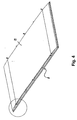
- FIG. 1 there is thus shown a perspective view of one embodiment of a system of panels according to the invention used to form a suspended ceiling.
- the system comprises a plurality of rows R1, R2 ... R6 of panels 2, each of the rows being in this embodiment separated from each other by intermediate channels 3, which can be used for the installation of for instance light armatures, sprinklers, loudspeakers etc. It should be understood, however, that the presence of these intermediate channels 3 is not a necessity, and that they could either be omitted altogether or some of the channels could be omitted, whereby corresponding adjacent rows would be placed in close proximity to each other.
- FIG. 2 With reference to Figure 2 , there is shown a perspective view of an embodiment of a single panel according to the invention.
- the panel basically comprises a substantially rigid frame consisting of lateral edge portions 4 and end portions 12 joined by corner portions 13, which will be described subsequently.
- the panel 2 could in principle be of any dimensions, but typical dimensions would be approximately 2 x 4 meters.
- a number of laterally extending beams 9 are provided on the rear side of the panel attached to either of the two lateral portions 4 of the frame. Apart from providing the necessary rigidity to the panel, at least some of these beams 9 serve as a means for suspending the panels from the fixed structure of the ceiling in a manner to be described in detail in the following.
- FIG. 3 A lateral cross sectional view of a panel according to the invention is shown in Figure 3 .
- a specific design of the frame 4 is apparent from Figure 3 , the cross section of the frame according to this design being of a substantially triangular shape comprising rounded edge portions 5 and a bottom portion 6. The bottom portion is inclined relative to the general plane of the panel, whereby the fabric 8 suspended over the opening through the frame only rests against the rounded edge portion 5.
- attachment means for the fabric On one of the legs of the triangle there is provided attachment means for the fabric and various alternative embodiments of these attachment means are described in the following.
- the laterally extending beams 9 are situated attached to the frame by suitable means and at least some of these beams 9 are on either end hereof provided with rail wheels 10 attached to the end faces of the beams by appropriate fittings 11.
- a variety of different fabrics can be used according to the specific application and pertinent characteristics of the fabric are for instance its transparency to light and/or sound and its fire-retarding ability.
- a presently preferred material is woven fibreglass. It should be noted, however, that a rigid panel could also replace the flexible material, if desired.
- the rear part of the panel can be left open, but it is also possible in addition to the fabric suspended over the opening through the frame as described above to provide the frame with additional layers of material, for instance in order to influence its acoustical properties, thermal properties, etc.
- An example of this is shown in Figure 4 , where the rear part of the panel has been covered by an additional fabric 14 stretched over the rear part of the panel.
- Such fabric could if desired be replaced by a substantially rigid panel, or a panel - for instance of mineral wool etc. - could be included between layers of fabric suspended over the front and rear parts of the panel.
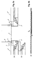
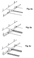
- FIG. 5a there is shown a detail of the system of panels according to the embodiment of the invention shown in Figure 1 .
- the Figure shows panels 2' and 2" belonging to two adjacent rows of the system shown in Figure 1 and separated from each other by the intermediate channel 3 as described previously.
- the cross section of the channel 3 is of an inverted U-shape with a substantially plane upper surface and substantially plane side portions forming the legs of the U-shape.
- the lower parts of the legs of the U are bent approximately 180 degrees to form rail members 3' running along the longitudinal direction of the channel 3.
- the channel 3 is fixed to the solid structure of the building, in this case to the (not shown) ceiling above the system of panels by suitable attachment means 17 distributed along the length of the channel.
- the beams 9 and the saddle members 15 are of a substantially square cross section in this embodiment, but it is understood that other cross sectional shapes could also be envisaged.
- the panels can be moved from an upper level (a) in which they form a portion of the complete system of panels, for instance a suspended ceiling, and at which level they are in a fixed relation to the system as determined by the position of the saddle members 15 on the corresponding side portions of the channels 3 downwards to a lower level (b), in which position they can be displaced in the direction of the corresponding row and underneath panels of that row situated at the upper level (a).
- This displacement is shown in Figure 5b .
- the movement from the upper level (a) to the lower level (b) is accomplished by lifting the beams 9 of the panel to be lowered upwardly out of the corresponding saddle members 15 as indicated by the arrow A in Figure 5c .
- the panel is then lowered, so that the rail wheels 10 of the panel are brought to rest on the corresponding rail members 3' on the side portions of the channel 3.
- the panel can now be displaced along the rail members 3' to a desired position, for instance underneath an adjacent panel of the particular row, whereby a passage to the space above the system of panels will be provided for instance for access to installations above the suspended ceiling.
- the rail wheels 10 ate attached to the end faces of the beams 9 by means of suitable fittings 11.
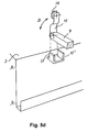
- Figure 5d shows holder means 15' in principle corresponding to those shown in Figure 5c (ref. numeral 15) and described in relation hereto.
- the holder means 15' are provided with upwardly open slots 33 facing the side surface of the channel 3 and that the fitting 11 of the rail wheel 10 is mounted for rotation as indicated by the arrow D at the end of the corresponding beam 9.
- the fitting 11 with the rail wheel 10 can be brought into a position where it extends substantially parallel with the upper surface of the channel 3, thereby leaving the space above the panels free of these fittings and wheels so that these do not interfere with installations in the space above the panels.
- holder means 34 in the form of a body, which could for instance be shaped as a box as shown in the Figure and provided with a central recess 35 of a cross-sectional shape corresponding to a mating tap 37 provided at the end face of the beam 9.
- the holder means 34 is furthermore provided with a downwardly extending passageway, which is made more narrow than the tap 37 through which the tap 37 can be inserted into the central recess 35.
- this embodiment requires that either the holder means 34 or the tap 37 be made of a suitably resilient material to allow the tap to pass through the passageway 36 and into the recess 35.
- the fitting 11 can be mounted for rotation (arrow D) as described above.
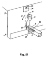
- FIG. 5f there is shown an alternative version of the holder means shown in Figure 5e .
- the passageway 36 has been omitted leaving only the recess 35 in the holder means 34.
- the tap 37 can be retracted towards the end of the beam 9, the tap being accommodated in a suitable channel in the beam and provided with biasing means 38 (for instance a compression spring) biasing it towards the channel 3 and with a grip member 39 for manual retraction of the tap (arrow E).
- biasing means 38 for instance a compression spring
- FIG. 7 A detail of a corresponding embodiment of the system according to the invention is shown in Figure 7 , where the U-shaped channel 3 has been replaced by a vertically extending fitting 31 on the lower end of which the rail members 3' are formed.
- the two attachment means 17 for attachment of the system to the solid structure above could of course be replaced by a single attachment means if desired.
- a first embodiment of releasable attachment means for the fabric stretched over the opening of the frame.
- These means comprise a dovetail slot 18 extending over the length of the corresponding part of the frame (i.e. along each of the lateral portions 4 of the frame and each of the end portions 12 of the frame) into which slot the fabric 8 is introduced.
- the fabric 8 is thus stretched over the opening of the frame, directed alongside the rounded edge portion 5 of the frame and from the edge portion 5 into the slot 18.
- a resilient clip 19 also of a dovetail shape, which due to its resiliency can be introduced into the slot 18.
- the clip is preferably provided with some kind of gripping means 20 to facilitate subsequent removal from the dovetail slot 18 in case removal of the fabric from the frame is desired.
- FIG. 8b An alternative embodiment of attachment means bearing some resemblance to the one shown in Figure 8a is shown in Figure 8b .
- the dovetail slot of the embodiment shown in Figure 8a is replaced by a slot comprising serrated side walls formed for engagement with a mating resilient clip 22, which could (although this is not shown) also be provided with gripping means for easy removal of the clip from the slot.
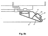
- FIG. 8c A further alternative embodiment of attachment means for the fabric is shown in Figure 8c .
- the dovetail slot and the slot with serrated side walls shown in Figures 8a and 8b have been replaced by a longitudinally extending cylindrical retainment channel 23 provided with an insertion opening 30 for insertion of the fabric 8 and for access to a retainment cylinder 24 accommodated within the channel and extending longitudinally throughout the length of the channel.
- the diameter of the retainment cylinder 24 is somewhat smaller than the diameter of the retainment channel, whereby a space is left between the channel and the cylinder at the portion of the channel substantially opposite the insertion opening 30.
- the circumferential surface of the cylinder is provided with radially extending notches, of which only some are shown in the Figure formed for engagement with a protrusion extending radially inwards towards the longitudinal axis of the cylinder 24.
- the notches are formed along the complete circumference of the cylinder as shown in Figure 8d .
- the circumferential surface of the cylinder could be knurled in order to increase friction between this surface and the fabric at a retaining contact surface 27 of the cylinder.
- the function of the attachment means for the fabric 8 according to the embodiment shown in Figure 8c is as follows: Initially, fabric 8 - without tension - is introduced through the opening 30 and into the space 28 between the retainment channel and the cylinder.
- the cylinder 24 is rotated by means of a suitably designed tool 29, which can engage notches 25 formed in the cylinder, in the direction of the arrow C in the Figure. Due to friction between the knurled circumferential surface of the cylinder and the fabric, the fabric is pulled through the opening 30 and into the space 28 behind the cylinder.
- FIG. 8d A modification of the cylinder 24 shown in Figure 8c is shown in Figure 8d comprising the pattern of notches 25 mentioned above.
- One of these notches 40 is, however, according to this modification extended radially inwards to a central region 41 of the cylinder 24.
- the fabric is introduced through this extended notch 40 and into the central region 41, which can accommodate a sufficiently large amount of fabric, and after this the cylinder 24 is rotated as described above to tension the fabric.
- the provision of the extended notch and the central region facilitates tensioning of the fabric at the initial phase, where practically no tension is yet built up in the fabric.
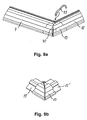
- FIG. 9a and 9b there is shown a schematic perspective representation of an embodiment of corner sections of the frame of the panels according to the invention.
- the corner section 13 according to this embodiment is provided with extensions 13' for insertion into corresponding profiles of the lateral edge portion 4 and the end portion 12 of the frame.
- the corner section can be provided with a groove 42 for insertion of the corner portion of the fabric, and this portion of the fabric can furthermore be retained in the groove 42 by means of a resilient member 43, for instance a piece of flexible cord of a suitable diameter.
- a resilient member 43 for instance a piece of flexible cord of a suitable diameter.
- Other retainment means can of course also be envisaged.
- the corner sections make it possible to assemble or disassemble the frame on site, which facilitates transport of the frame.
- FIG. 10 there is shown a cross sectional view of a further embodiment of attachment means for the fabric 8 to the frame.
- a laterally displaceable member essentially comprising two portions, i.e. a guide portion 44 of such a shape that it can be at least partly accommodated within a corresponding guide channel 45 formed in the frame and displaced laterally herein, i.e. away from or towards the edge portion 5 of the frame.
- the other portion of the laterally displaceable member is the attachment portion 46, to which the fabric to be stretched over the open region of the frame is fastened.
- the fastening is accomplished by means of a resilient clip 47, but other means would also be conceivable.
- the laterally displaceable member is urged away from the edge portion 5 of the frame for instance by means of a compression spring 48.
- this member can be prevented from movement away from the edge portion 5 of the frame by means of a spacer 49 inserted between the laterally displaceable member and the frame structure.
Landscapes
- Engineering & Computer Science (AREA)
- Architecture (AREA)
- Physics & Mathematics (AREA)
- Electromagnetism (AREA)
- Civil Engineering (AREA)
- Structural Engineering (AREA)
- Building Environments (AREA)
- Finishing Walls (AREA)
- Connection Of Plates (AREA)
- Curtains And Furnishings For Windows Or Doors (AREA)
- Support Devices For Sliding Doors (AREA)
- Conveying And Assembling Of Building Elements In Situ (AREA)
- Floor Finish (AREA)
Claims (22)
- Eine Anordnung von Deckenelementen für abgehängte Decken oder dergleichen, umfassend(a) eine oder mehrere Reihen (R1, R2 ...) von planparallelen Deckenelementen (2);(b) eine Abhäng- und Führungsanordnung für die besagten Deckenelementen (2),wo die besagte Abhäng- und Führungsanordnung zur Abhängung und Führung der Deckenelemente (2) so eingerichtet ist, dass mindestens einige der Deckenelemente einer gegebenen Reihe (R1, R2 ...) von einer ersten Höhenebene auf eine zweite Höhenebene bewegt werden können, auf welcher letzteren Ebene die Deckenelemente entlang sich auf der ersten Ebene befindlichen Deckenelementen verschoben werden können, wobei Zugang durch die Anordnung von Deckenelementen geschaffen wird, welche Anordnung entweder
einen oder mehrere Zwischenkanäle (3) umfasst, die eine im wesentlichen plane Oberfläche und im wesentlichen plane Seitenteile umfassen, welche an ihrem von der besagten Oberfläche am längsten entfernten Ende mit Schienenteilen (3') versehen sind, die in Längsrichtung das Kanals (3) verlaufen,
oder ein Fitting (31), dessen eines Ende mit den besagten Schienenteilen (3') versehen ist,
dadurch gekennzeichnet, dass die besagte Abhäng- und Führungsanordnung ausserdem Halterorgane (15,34) umfasst, die sich lateral von den besagten, im wesentlichen planen Seitentellen der Zwischenkanäle (3) oder von dem besagten Fitting (31) erstrecken, welche Halterorgane (15, 34) sich an vorausbestimmten Stellen entlang der longitudinalen Erstreckung der Reihen befinden zum lösbaren Eingriff mit entsprechenden, sich lateral erstreckenden Träger- oder Zapfenelementen (9, 37), die an den Deckenelementen (2) vorgesehen sind, um die Deckenelemente (2) an festgelegten Stellen entlang der entsprechenden Reihe festzuhalten, wenn das Deckenelement (2) sich auf der ersten der genannten Ebenen befindet, indem die Schienenorgane (3') auf einer niedrigeren Ebene als die besagten Halterorgane (15, 34) vorgesehen sind und zum verschiebbaren Eingriff mit entsprechenden, an den Deckenelementen angebrachten Verschiebungsorganen (10) angepasst sind, sodass die Deckenelemente, wenn sie sich auf der zweiten der besagten Ebenen befinden, in Längsrichtung entlang der Reihen verschoben werden können. - Eine Anordnung von Deckenelementen gemäss Anspruch 1, dadurch qekennzeichnet, dass zwischen benachbarten Reihen von Deckenelementen (2) ein Zwischenkanal vorgesehen ist.
- Eine Anordnung von Deckenelementen gemäss Anspruch 1, dadurch gekennzeichet, dass benachbarte Reihen von Deckenelementen (2) im wesentlichen aneinander grenzen.
- Eine Anordnung von Deckenelementen gemäss Anspruch 1, 2 oder 3, dadurch gekennzeichnet, dass die Deckenelemente, wenn sie sich auf der besagten ersten Ebene befinden, sich an einer festgelegten Stelle in Längsrichtung der entsprechenden Reihe befinden.
- Ein Deckenelement zum Gebrauch in einer Anordnung von Deckenelementen gemäss einem jeglichen der vorhergehenden Ansprüche 1 bis 5, umfassend einen im wesentlichen steifen Rahmen (6, 12), dadurch gekennzeichnet, dass der Rahmen mit sich lateral erstreckenden Träger- oder Zapfenelementen (9, 37) versehen ist zum lösbaren Eingriff in entsprechende Halterorgane (15, 34) der besagten Abhäng- und Führungsanordnung, und Verschiebungsorgane (10) zur Kooperation mit den besagten Schienenorganen (3') der Abhäng- und Führungsanordnung, wobei die Verschlebungsorgane (10) mit Hilfe eines mit den besagten Träger- oder Zapfenelementen (9, 37) verbundenen Fittings (11) auf einer gewählten Anzahl der besagten Träger- oder Zapfenelemente (9, 37) angebracht sind und sich über der Ebene der Träger- oder Zapfenelemente (9, 37) befinden.
- Ein Deckenelement gemäss Anspruch 5, dadurch gekennzeichnet, dass die besagten Halterorgane als ein Muster von Vorsprüngen ausgeformt sind, das auf zwei einander gegenüberliegenden longitudinalen Kanten des besagten Rahmens angebracht ist.
- Ein Deckenelement gemäss Anspruch 5, dadurch gekennzeichnet, dass die besagten Halterorgane aus Endteilen von sich lateral erstreckenden Trägern gebildet werden, welche die zwei einander gegenüberliegenden longitudinalen Kanten des besagten Rahmens verbinden.
- Ein Deckenelement gemäss Anspruch 5, dadurch gekennzeichnet, dass die besagten Verschiebungsorgane Schienenräder (10) sind, die an den lateralen Teilen (4) des Rahmens befestigt sind.
- Ein Deckenelement gemäss Anspruch 5, dadurch gekennzeichnet, dass der besagte Rahmen einen Bereich definiert, der mit einem Material (8) bedeckt ist und damit den Hauptteil der Oberfläche des Deckenelements bildet.
- Ein Deckenelement gemäss Anspruch 9, dadurch gekennzeichnet, dass das flexible Sheetmaterial Glasfaser ist.
- Ein Deckenelement gemäss Anspruch 5, dadurch gekennzeichnet, dass das Deckenelement mit einer oder mehreren weiteren Materiallagen (14) über dem besagten Sheet (8) versehen ist.
- Ein Deckenelement gemäss Anspruch 5, dadurch gekennzeichnet, dass es Eckteile (13) umfasst zur lösbaren Befestigung an den lateralen Teilen (4) und den Endteilen (12) des Rahmens.
- Ein Deckenelement gemäss Anspruch 9, dadurch gekennzeichnet, dass das besagte Deckmaterial (8) mit Hilfe von Befestigungsorganen, die einen sich entlang eines lateralen Teils des Rahmens (4, 12) erstreckenden Schwalbenschwanzschlitz (18) und einen entsprechend geformten elastischen Clip (19) umfassen, lösbar am Rahmen (4, 12) befestigt ist, wodurch das Gewebe (8) nach Einführung des Gewebes in den Schlitz (18) und Einführung des Clips in den Schlitz über dem Gewebe zwischen der Oberfläche des Schwalbenschwanzschlitzes (18) und dem Clip (19) festgeklemmt wird.
- Ein Deckenelement gemäss Anspruch 9, dadurch gekennzeichnet, dass das besagte Deckmaterial (8) mit Hilfe von Befestigungsorganen, die einen sich entlang einem lateralen Teil des Rahmens (4, 12) erstreckenden Schlitz umfassen, lösbar am Rahmen (4, 12) befestigt ist, indem der besagte Schlitz mit gezahnten Seitenflächen (21) versehen ist zum Eingriff mit einem entsprechend geformten Clip (22), wodurch das Gewebe (8) nach Einführung des Gewebes in den Schlitz und Einführung des Clips in den Schlitz über dem Gewebe zwischen den gezahnten Oberflächen des Schlitzes und dem Clip (22) festgeklemmt wird.
- Ein Deckenelement gemäss Anspruch 9, dadurch gekennzeichnet, dass das besagte Deckmaterial (8) mit Hilfe von Befestigungsorganen, die einen sich entlang einem lateralen Teil des Rahmens (4, 12) erstreckenden Schlitz umfassen, lösbar am Rahmen (4, 12) befestigt ist, indem der besagte Schlitz einen im wesentlichen zylindrischen Querschnitt aufweist und ein im wesentlichen zylindrisches Rückhalteelement (24) beherbergt, dessen Diameter kleiner ist als der des zylindrischen Schlitzes, wo das besagte Rückhalteelement (24) auf seiner peripheren Oberfläche mit einer Mehrheit von sich radial erstreckenden Aussparungen (25) versehen ist zum Eingriff mit einem Vorsprung (26) auf einer Kante des besagten Schlitzes, wodurch das Gewebe zwischen der Innenfläche des zylindrischen Schlitzes und der Aussenfläche des zylindrischen Rückhalteelements (24) eingeklemmt werden kann, und wo das Gewebe durch Rotation des Rückhalteelements (24) im Schlitz gespannt werden kann.
- Ein Deckenelement gemäss Anspruch 15, dadurch gekennzeichnet, dass das zylindrische Rückhalteelement (24) mit einer gerändelten peripheren Oberfläche versehen ist.
- Ein Deckenelement gemäss Anspruch 15, dadurch gekennzeichnet, dass das zylindrische Rückhaltelement (24) mit mindestens einer Aussparung (40) versehen ist, die sich von der peripheren Oberfläche des Zylinders (24) zu einem zentralen Bereich (41) erstreckt, wodurch das Gewebe (8) durch die besagte Aussparung (40) in den zentralen Bereich (41) eingeführt werden kann, welcher eine bestimmte Menge Gewebe beherbergen kann.
- Ein Deckenelement gemäss Anspruch 9, dadurch gekennzeichnet, dass der Rahmen mindestens entlang von Teilen der Peripherie des Rahmens mit lateral verschiebbaren Befestigungselementen (44, 46) versehen ist, die von der Aussenseite des Rahmens zugänglich sind zur Befestigung des Gewebes (8) am Rahmen, wo eine laterale Verschiebung der besagten Elemente (44, 46) hinweg von dem entsprechenden Kantteil (5) des Rahmens in der Spannung des Gewebes (8) quer durch den offenen Bereich des Rahmens resultiert.
- Ein Deckenelement gemäss Anspruch 18, dadurch gekennzeichnet, dass das besagte lateral verschiebbare Element einen Führungsteil (44) umfasst zur Führung desselben in einem Führungskanal (45) im Rahmen, und einen Befestigungsteil (46) zur Befestigung des Gewebes (8) an dem verschiebbaren Element.
- Ein Deckenelement gemäss Anspruch 19, dadurch gekennzeichnet, dass das besagte Gewebe (8) mit Hilfe eines elastischen Clips (47) lösbar an dem besagten Befestigungsteil (46) befestigt ist.
- Ein Deckenelement gemäss Anspruch 18 oder 19, dadurch gekennzeichnet, dass das besagte lateral verschiebbare Element (44, 46) hinweg von dem besagten entsprechenden Kantteil (5) des Rahmens vorgespannt ist.
- Ein Deckenelement gemäss Anspruch 18, dadurch gekennzeichnet, dass das besagte lateral verschiebbare Element (44, 46) eine solche Form hat, dass Abstandsorgane 49 zwischen dem lateral verschiebbaren Element (44, 46) und dem Rahmen eingefügt werden können, um die Verschiebung des Elements (44, 46) während der Montage des Gewebes (8) zu begrenzen.
Priority Applications (11)
| Application Number | Priority Date | Filing Date | Title |
|---|---|---|---|
| EP09000596.8A EP2048299B1 (de) | 2004-01-28 | 2004-09-28 | Abdeckelement insbesondere für abgehängte Decken |
| DK09000596.8T DK2048299T3 (en) | 2004-01-28 | 2004-09-28 | Covering panel, especially for suspended ceilings |
| EP04022999A EP1559846B1 (de) | 2004-01-28 | 2004-09-28 | Deckenelemente und Anordnungen solcher Deckenelemente für abgehängte Decken |
| CA2578867A CA2578867C (en) | 2004-01-28 | 2005-01-27 | Panels and systems of such panels for instance for suspended ceilings |
| CN2010101680220A CN101839035B (zh) | 2004-01-28 | 2005-01-27 | 板 |
| US10/593,566 US7954293B2 (en) | 2004-01-28 | 2005-01-27 | Panels and systems of such panels for instance for suspended ceilings |
| AU2005209486A AU2005209486B2 (en) | 2004-01-28 | 2005-01-27 | Panels and systems of such panels for instance for suspended ceilings |
| PCT/IB2005/050349 WO2005073482A2 (en) | 2004-01-28 | 2005-01-27 | Panels and systems of such panels for instance for suspended ceilings |
| CN200580010016XA CN1938486B (zh) | 2004-01-28 | 2005-01-27 | 板和用于例如悬挂的天花板的板组件 |
| AU2009250953A AU2009250953B2 (en) | 2004-01-28 | 2009-12-15 | Panels and systems of such panels for instance for suspended ceilings |
| HK11102318.8A HK1148327B (zh) | 2004-01-28 | 2011-03-08 | 板 |
Applications Claiming Priority (3)
| Application Number | Priority Date | Filing Date | Title |
|---|---|---|---|
| EP04001760 | 2004-01-28 | ||
| EP04001760 | 2004-01-28 | ||
| EP04022999A EP1559846B1 (de) | 2004-01-28 | 2004-09-28 | Deckenelemente und Anordnungen solcher Deckenelemente für abgehängte Decken |
Related Child Applications (1)
| Application Number | Title | Priority Date | Filing Date |
|---|---|---|---|
| EP09000596.8A Division EP2048299B1 (de) | 2004-01-28 | 2004-09-28 | Abdeckelement insbesondere für abgehängte Decken |
Publications (2)
| Publication Number | Publication Date |
|---|---|
| EP1559846A1 EP1559846A1 (de) | 2005-08-03 |
| EP1559846B1 true EP1559846B1 (de) | 2009-02-04 |
Family
ID=34655123
Family Applications (2)
| Application Number | Title | Priority Date | Filing Date |
|---|---|---|---|
| EP04022999A Expired - Lifetime EP1559846B1 (de) | 2004-01-28 | 2004-09-28 | Deckenelemente und Anordnungen solcher Deckenelemente für abgehängte Decken |
| EP09000596.8A Expired - Lifetime EP2048299B1 (de) | 2004-01-28 | 2004-09-28 | Abdeckelement insbesondere für abgehängte Decken |
Family Applications After (1)
| Application Number | Title | Priority Date | Filing Date |
|---|---|---|---|
| EP09000596.8A Expired - Lifetime EP2048299B1 (de) | 2004-01-28 | 2004-09-28 | Abdeckelement insbesondere für abgehängte Decken |
Country Status (7)
| Country | Link |
|---|---|
| US (1) | US7954293B2 (de) |
| EP (2) | EP1559846B1 (de) |
| CN (1) | CN101839035B (de) |
| AU (2) | AU2005209486B2 (de) |
| CA (1) | CA2578867C (de) |
| DK (1) | DK2048299T3 (de) |
| WO (1) | WO2005073482A2 (de) |
Families Citing this family (23)
| Publication number | Priority date | Publication date | Assignee | Title |
|---|---|---|---|---|
| US7536836B2 (en) * | 2005-01-13 | 2009-05-26 | Roberto Felipe Moser Rossel | Removable ceiling panel |
| FR2892739B1 (fr) * | 2005-11-03 | 2008-01-18 | Newmat Sa Sa | Profil pour cadre a empocher |
| DE102005060643A1 (de) * | 2005-12-05 | 2007-09-20 | Protektorwerk Florenz Maisch Gmbh & Co Kg | Aufdopplungsprofil |
| EP1914359A1 (de) * | 2006-10-16 | 2008-04-23 | Ibmo International Ag | Deckenkonstruktion |
| PL200284B1 (pl) * | 2007-07-30 | 2008-12-31 | Kramarz Jozef | Moduł jednostkowy panela i sposób mocowania pokrycia |
| EP2444561B1 (de) | 2010-10-25 | 2013-07-17 | Soft Cells A/S | Paneel |
| ITTO20110311A1 (it) * | 2011-04-06 | 2012-10-07 | Rostagno S R L | Controsoffitto per l'isolamento acustico e termico di un ambiente |
| FR2979116B1 (fr) * | 2011-08-17 | 2016-12-09 | Normalu | Caisson lumineux a cadre mobile. |
| US8646238B2 (en) * | 2011-12-22 | 2014-02-11 | Usg Interiors, Llc | Apparatus, system, and method for facilitating use of thin flexible scrims in a grid-type suspended ceiling |
| FR2984933B1 (fr) * | 2011-12-23 | 2021-06-25 | Normalu | Lisse pour cadre de fausse paroi notamment de faux plafond. |
| US9217247B2 (en) | 2014-02-07 | 2015-12-22 | Apple Inc. | Ceiling system |
| FR3031352B1 (fr) * | 2015-01-07 | 2017-01-20 | Normalu | Lisse pour la realisation d'un cadre de dalle pour fausse paroi comportant des zones pleines definissant des zones de renfort |
| AU2016413696B2 (en) * | 2016-07-08 | 2021-08-19 | Kvadrat Soft Cells A/S | Panel for a suspended ceiling or the like and method of mounting a fabric on a frame of a suspended ceiling or the like |
| EP3529432B1 (de) | 2016-10-24 | 2021-01-13 | Kvadrat Soft Cells A/S | Befestigungsvorrichtung und system zum befestigen von paneelen an eine struktur |
| US11091909B2 (en) | 2017-05-08 | 2021-08-17 | Kvadrat Soft Cells A/S | Building panel adapted to be mounted at a ceiling or wall of a room and method of manufacturing such building panel |
| ES2903350T3 (es) | 2017-05-19 | 2022-04-01 | Kvadrat Soft Cells As | Panel de construcción adaptado para montarse en un techo o pared de una sala y método de fabricación de tal panel de construcción |
| GB2572436A (en) * | 2018-03-29 | 2019-10-02 | Sas International Ltd | A sound-absorbing raft |
| CN112204204A (zh) | 2018-05-29 | 2021-01-08 | 克瓦德拉特软格有限公司 | 适于安装在房间的顶部或墙壁处的建筑面板及这种建筑面板的制造方法 |
| US11286662B2 (en) | 2019-02-22 | 2022-03-29 | Certainteed Canada, Inc. | Framed acoustic panel and method of manufacture |
| EP4407109A1 (de) | 2023-01-27 | 2024-07-31 | Kvadrat Acoustics A/S | Bauplatte zur montage an einer decke oder wand eines raumes und verfahren zur herstellung solch einer bauplatte |
| EP4407110A1 (de) | 2023-01-27 | 2024-07-31 | Kvadrat Acoustics A/S | Bauplatte zur montage an einer decke oder wand eines raumes und verfahren zur herstellung solch einer bauplatte |
| EP4678840A1 (de) | 2024-07-11 | 2026-01-14 | Kvadrat Acoustics A/S | Bauplatte zur montage an einer decke oder wand eines raumes und verfahren zur herstellung solch einer bauplatte |
| WO2026012905A1 (en) | 2024-07-11 | 2026-01-15 | Kvadrat Acoustics A/S | Building panel adapted to be mounted at a ceiling or wall of a room and method of manufacturing such building panel |
Family Cites Families (38)
| Publication number | Priority date | Publication date | Assignee | Title |
|---|---|---|---|---|
| US182894A (en) * | 1876-10-03 | Improvement in mortising-chisels | ||
| US2897889A (en) * | 1957-05-27 | 1959-08-04 | Kessler Gerald | Screen spline with direct frictional engagement means |
| US3165110A (en) * | 1961-08-11 | 1965-01-12 | Thomas W Brooks | Building construction |
| GB1001485A (en) | 1961-11-15 | 1965-08-18 | Isora Illuminating Ceilings Lt | Improvements in or relating to ceilings or walls |
| US3374597A (en) * | 1965-03-09 | 1968-03-26 | Universal Molding Company | Rolled metal screen frame |
| DE2129051A1 (de) * | 1971-06-11 | 1972-12-21 | Kreuzer, Horst, 4407 Emsdetten | Hangedecke, insbesondere fur Aus stellungsraume |
| US3791076A (en) * | 1971-12-27 | 1974-02-12 | Smith X S Inc | Plastic covered building structures |
| DE2531026C3 (de) | 1975-07-11 | 1979-03-22 | Wilhelm Baeder Kg Lichttechnische Spezialfabrik, 7014 Kornwestheim | Plattenförmiges Element zur Deckenoder Wandbekleidung |
| US4195455A (en) * | 1978-05-17 | 1980-04-01 | Alcan Aluminum Corporation | Adjustable soffit system |
| DE3024110A1 (de) * | 1980-06-27 | 1982-01-21 | Bäder Leuchten GmbH, 7012 Fellbach | Kassettenelement fuer eine deckenverkleidung |
| US4522007A (en) * | 1983-11-17 | 1985-06-11 | Oehlert James A | Interlocking building panel |
| US4640064A (en) * | 1985-03-18 | 1987-02-03 | Donn Incorporated | Suspension ceiling system combining snap-up pans and lay-in panels |
| EP0246391A1 (de) * | 1986-05-22 | 1987-11-25 | Ag Dixxema | Verkleidungssystem für Bauwerke |
| US4696142A (en) * | 1986-09-26 | 1987-09-29 | Donn Incorporated | Suspension ceiling with snap-up panels |
| US4962612A (en) * | 1987-04-23 | 1990-10-16 | Nisshin Steel Co., Ltd. | Decorative panel as construction material |
| DE3827918A1 (de) * | 1988-08-17 | 1990-02-22 | Nickel Gmbh Heinrich | Laminarisator |
| US4901485A (en) * | 1989-04-06 | 1990-02-20 | National Gypsum Company | Acoustical panel |
| DE3916687A1 (de) * | 1989-05-23 | 1990-11-29 | Koester Helmut | Klimadecke |
| FR2664633A1 (fr) * | 1990-07-11 | 1992-01-17 | Leveau Jean Claude | Plafond suspendu. |
| US5209029A (en) * | 1991-10-18 | 1993-05-11 | Extrusion 2001, Inc. | Construction assembly for awnings |
| FR2688551B1 (fr) * | 1992-03-13 | 1995-06-30 | Bonnemaison Daniele | Pince d'attache reglable pour fixer et tendre une toile ou analogue sur un cadre. |
| DE9410031U1 (de) * | 1994-06-23 | 1994-09-29 | Hunter Douglas Bensheim GmbH, 64625 Bensheim | Unterdecke für Gebäuderäume |
| FR2733805B1 (fr) * | 1995-05-03 | 1997-07-18 | Pingon Maurice | Panneau d'affichage constitue d'une toile tendue sur un cadre |
| FR2741099B1 (fr) | 1995-11-15 | 2001-06-29 | Gagliardi Marc | Nouveau dispositif de revetements muraux et moyens propres a cette realisation |
| DE19702099C2 (de) | 1997-01-22 | 1999-06-02 | Lindner Ag | Deckenaufbau |
| DE29804242U1 (de) * | 1997-01-22 | 1998-06-25 | Lindner AG, 94424 Arnstorf | Deckenaufbau |
| US6108994A (en) | 1998-08-12 | 2000-08-29 | Armstrong World Industries, Inc. | Ceiling panel |
| AU3241901A (en) * | 1999-12-10 | 2001-06-18 | Rogier De La Rive Box | Clamping apparatus |
| EP1132540A1 (de) | 2000-03-10 | 2001-09-12 | Rockwool International A/S | Verfahren zum Einbau von Deckenpaneelen |
| DE20011581U1 (de) * | 2000-07-03 | 2000-09-14 | FURAL GmbH Vertrieb von Metalldeckensystemen, 84359 Simbach | Deckenelement und Kassettendecke aus diesen Deckenelementen |
| CN1123669C (zh) * | 2000-08-02 | 2003-10-08 | 佳埼工程有限公司 | 楼层板悬吊装置 |
| US6499262B1 (en) | 2000-09-11 | 2002-12-31 | Frank Novak & Sons, Inc. | Ceiling panel |
| US6431251B1 (en) * | 2000-11-27 | 2002-08-13 | Snap-Tex International L.L.C. | Mid-wall hanger |
| US6574936B1 (en) * | 2001-05-11 | 2003-06-10 | Accutrack Systems, Inc. | Fabric wall panel system |
| DE10145244B4 (de) * | 2001-09-13 | 2005-10-13 | Manfred Kluth | Beleuchtungskörper |
| US6722096B2 (en) * | 2002-01-23 | 2004-04-20 | Quanex Corporation | Frame assembly and frame component for tensioning fabric about a panel of a partition system |
| FR2864566B1 (fr) * | 2003-12-24 | 2006-03-17 | Jean Marc Scherrer | Fausses parois en toile tendue reunies par une lisse separateur inclinee |
| US20070283656A1 (en) * | 2006-06-12 | 2007-12-13 | Anderson Andy W | Fabric Wall Panel System and Track |
-
2004
- 2004-09-28 EP EP04022999A patent/EP1559846B1/de not_active Expired - Lifetime
- 2004-09-28 EP EP09000596.8A patent/EP2048299B1/de not_active Expired - Lifetime
- 2004-09-28 DK DK09000596.8T patent/DK2048299T3/en active
-
2005
- 2005-01-27 AU AU2005209486A patent/AU2005209486B2/en not_active Expired
- 2005-01-27 CA CA2578867A patent/CA2578867C/en not_active Expired - Lifetime
- 2005-01-27 WO PCT/IB2005/050349 patent/WO2005073482A2/en not_active Ceased
- 2005-01-27 US US10/593,566 patent/US7954293B2/en active Active
- 2005-01-27 CN CN2010101680220A patent/CN101839035B/zh not_active Expired - Lifetime
-
2009
- 2009-12-15 AU AU2009250953A patent/AU2009250953B2/en not_active Expired
Also Published As
| Publication number | Publication date |
|---|---|
| WO2005073482A2 (en) | 2005-08-11 |
| CN101839035A (zh) | 2010-09-22 |
| EP1559846A1 (de) | 2005-08-03 |
| WO2005073482A3 (en) | 2005-10-20 |
| EP2048299B1 (de) | 2017-04-19 |
| AU2009250953A1 (en) | 2010-01-07 |
| AU2005209486A1 (en) | 2005-08-11 |
| EP2048299A3 (de) | 2010-06-09 |
| CA2578867A1 (en) | 2005-08-11 |
| AU2005209486B2 (en) | 2009-09-17 |
| HK1148327A1 (en) | 2011-09-02 |
| CN101839035B (zh) | 2012-06-27 |
| AU2009250953B2 (en) | 2011-10-20 |
| US7954293B2 (en) | 2011-06-07 |
| EP2048299A2 (de) | 2009-04-15 |
| US20080066394A1 (en) | 2008-03-20 |
| CA2578867C (en) | 2013-01-08 |
| DK2048299T3 (en) | 2017-07-31 |
Similar Documents
| Publication | Publication Date | Title |
|---|---|---|
| EP1559846B1 (de) | Deckenelemente und Anordnungen solcher Deckenelemente für abgehängte Decken | |
| CA2361963C (en) | Hinged ceiling panel | |
| EP2126238B1 (de) | Deckenaufhängungssystem | |
| AU2013354984B2 (en) | Ceiling system | |
| US7406802B2 (en) | Panel structures and mounting therefore | |
| EP2631380B1 (de) | Abgehängte Decke, Deckenelement und zugehöriges Montageverfahren | |
| US20120291397A1 (en) | Mounting hardware and mounting system for vertical panels | |
| AU2012255734A1 (en) | Mounting hardware and mounting system for vertical panels | |
| CA2360141A1 (en) | Supporting means for elongated building services supply means | |
| AU2015346135B2 (en) | Ceiling system | |
| CA2572571A1 (en) | Curved ceiling panel | |
| KR102683304B1 (ko) | 탄성와이어가 장착된 클립브라켓 및 클립브라켓이 적용된 내진천장시스템 | |
| US2789321A (en) | Acoustical ceiling construction | |
| EP3371388B1 (de) | Deckensystem | |
| CA2592789A1 (en) | Adaptable ceiling tile system | |
| JP7441354B1 (ja) | システム天井 | |
| HK1148327B (zh) | 板 | |
| JP7348785B2 (ja) | 天井構造及び天井構造の施工方法 | |
| KR102672489B1 (ko) | 원터치 결속형 다용도 마개 | |
| KR101714584B1 (ko) | 크린룸의 천장판넬 시공장치 | |
| AU2248199A (en) | Curtain track | |
| JPH07180264A (ja) | 天井構造 |
Legal Events
| Date | Code | Title | Description |
|---|---|---|---|
| PUAI | Public reference made under article 153(3) epc to a published international application that has entered the european phase |
Free format text: ORIGINAL CODE: 0009012 |
|
| AK | Designated contracting states |
Kind code of ref document: A1 Designated state(s): AT BE BG CH CY CZ DE DK EE ES FI FR GB GR HU IE IT LI LU MC NL PL PT RO SE SI SK TR |
|
| AX | Request for extension of the european patent |
Extension state: AL HR LT LV MK |
|
| 17P | Request for examination filed |
Effective date: 20060203 |
|
| RAP1 | Party data changed (applicant data changed or rights of an application transferred) |
Owner name: SOFT CELLS A/S |
|
| AKX | Designation fees paid |
Designated state(s): AT BE BG CH CY CZ DE DK EE ES FI FR GB GR HU IE IT LI LU MC NL PL PT RO SE SI SK TR |
|
| RAP1 | Party data changed (applicant data changed or rights of an application transferred) |
Owner name: SOFT CELLS A/S |
|
| GRAP | Despatch of communication of intention to grant a patent |
Free format text: ORIGINAL CODE: EPIDOSNIGR1 |
|
| GRAS | Grant fee paid |
Free format text: ORIGINAL CODE: EPIDOSNIGR3 |
|
| GRAA | (expected) grant |
Free format text: ORIGINAL CODE: 0009210 |
|
| AK | Designated contracting states |
Kind code of ref document: B1 Designated state(s): AT BE BG CH CY CZ DE DK EE ES FI FR GB GR HU IE IT LI LU MC NL PL PT RO SE SI SK TR |
|
| REG | Reference to a national code |
Ref country code: GB Ref legal event code: FG4D |
|
| REG | Reference to a national code |
Ref country code: CH Ref legal event code: EP |
|
| REG | Reference to a national code |
Ref country code: IE Ref legal event code: FG4D |
|
| REF | Corresponds to: |
Ref document number: 602004019325 Country of ref document: DE Date of ref document: 20090319 Kind code of ref document: P |
|
| NLV1 | Nl: lapsed or annulled due to failure to fulfill the requirements of art. 29p and 29m of the patents act | ||
| PG25 | Lapsed in a contracting state [announced via postgrant information from national office to epo] |
Ref country code: FI Free format text: LAPSE BECAUSE OF FAILURE TO SUBMIT A TRANSLATION OF THE DESCRIPTION OR TO PAY THE FEE WITHIN THE PRESCRIBED TIME-LIMIT Effective date: 20090204 Ref country code: NL Free format text: LAPSE BECAUSE OF FAILURE TO SUBMIT A TRANSLATION OF THE DESCRIPTION OR TO PAY THE FEE WITHIN THE PRESCRIBED TIME-LIMIT Effective date: 20090204 Ref country code: ES Free format text: LAPSE BECAUSE OF FAILURE TO SUBMIT A TRANSLATION OF THE DESCRIPTION OR TO PAY THE FEE WITHIN THE PRESCRIBED TIME-LIMIT Effective date: 20090515 Ref country code: SI Free format text: LAPSE BECAUSE OF FAILURE TO SUBMIT A TRANSLATION OF THE DESCRIPTION OR TO PAY THE FEE WITHIN THE PRESCRIBED TIME-LIMIT Effective date: 20090204 |
|
| PG25 | Lapsed in a contracting state [announced via postgrant information from national office to epo] |
Ref country code: SE Free format text: LAPSE BECAUSE OF FAILURE TO SUBMIT A TRANSLATION OF THE DESCRIPTION OR TO PAY THE FEE WITHIN THE PRESCRIBED TIME-LIMIT Effective date: 20090504 Ref country code: AT Free format text: LAPSE BECAUSE OF FAILURE TO SUBMIT A TRANSLATION OF THE DESCRIPTION OR TO PAY THE FEE WITHIN THE PRESCRIBED TIME-LIMIT Effective date: 20090204 Ref country code: PL Free format text: LAPSE BECAUSE OF FAILURE TO SUBMIT A TRANSLATION OF THE DESCRIPTION OR TO PAY THE FEE WITHIN THE PRESCRIBED TIME-LIMIT Effective date: 20090204 |
|
| PG25 | Lapsed in a contracting state [announced via postgrant information from national office to epo] |
Ref country code: BE Free format text: LAPSE BECAUSE OF FAILURE TO SUBMIT A TRANSLATION OF THE DESCRIPTION OR TO PAY THE FEE WITHIN THE PRESCRIBED TIME-LIMIT Effective date: 20090204 |
|
| PG25 | Lapsed in a contracting state [announced via postgrant information from national office to epo] |
Ref country code: CZ Free format text: LAPSE BECAUSE OF FAILURE TO SUBMIT A TRANSLATION OF THE DESCRIPTION OR TO PAY THE FEE WITHIN THE PRESCRIBED TIME-LIMIT Effective date: 20090204 Ref country code: EE Free format text: LAPSE BECAUSE OF FAILURE TO SUBMIT A TRANSLATION OF THE DESCRIPTION OR TO PAY THE FEE WITHIN THE PRESCRIBED TIME-LIMIT Effective date: 20090204 Ref country code: PT Free format text: LAPSE BECAUSE OF FAILURE TO SUBMIT A TRANSLATION OF THE DESCRIPTION OR TO PAY THE FEE WITHIN THE PRESCRIBED TIME-LIMIT Effective date: 20090706 Ref country code: DK Free format text: LAPSE BECAUSE OF FAILURE TO SUBMIT A TRANSLATION OF THE DESCRIPTION OR TO PAY THE FEE WITHIN THE PRESCRIBED TIME-LIMIT Effective date: 20090204 |
|
| PG25 | Lapsed in a contracting state [announced via postgrant information from national office to epo] |
Ref country code: SK Free format text: LAPSE BECAUSE OF FAILURE TO SUBMIT A TRANSLATION OF THE DESCRIPTION OR TO PAY THE FEE WITHIN THE PRESCRIBED TIME-LIMIT Effective date: 20090204 Ref country code: RO Free format text: LAPSE BECAUSE OF FAILURE TO SUBMIT A TRANSLATION OF THE DESCRIPTION OR TO PAY THE FEE WITHIN THE PRESCRIBED TIME-LIMIT Effective date: 20090204 |
|
| PLBE | No opposition filed within time limit |
Free format text: ORIGINAL CODE: 0009261 |
|
| STAA | Information on the status of an ep patent application or granted ep patent |
Free format text: STATUS: NO OPPOSITION FILED WITHIN TIME LIMIT |
|
| 26N | No opposition filed |
Effective date: 20091105 |
|
| PG25 | Lapsed in a contracting state [announced via postgrant information from national office to epo] |
Ref country code: BG Free format text: LAPSE BECAUSE OF FAILURE TO SUBMIT A TRANSLATION OF THE DESCRIPTION OR TO PAY THE FEE WITHIN THE PRESCRIBED TIME-LIMIT Effective date: 20090504 |
|
| PG25 | Lapsed in a contracting state [announced via postgrant information from national office to epo] |
Ref country code: MC Free format text: LAPSE BECAUSE OF NON-PAYMENT OF DUE FEES Effective date: 20090930 |
|
| REG | Reference to a national code |
Ref country code: CH Ref legal event code: PL |
|
| REG | Reference to a national code |
Ref country code: IE Ref legal event code: MM4A |
|
| REG | Reference to a national code |
Ref country code: FR Ref legal event code: ST Effective date: 20100531 |
|
| PG25 | Lapsed in a contracting state [announced via postgrant information from national office to epo] |
Ref country code: FR Free format text: LAPSE BECAUSE OF NON-PAYMENT OF DUE FEES Effective date: 20090930 Ref country code: IE Free format text: LAPSE BECAUSE OF NON-PAYMENT OF DUE FEES Effective date: 20090928 |
|
| PG25 | Lapsed in a contracting state [announced via postgrant information from national office to epo] |
Ref country code: LI Free format text: LAPSE BECAUSE OF NON-PAYMENT OF DUE FEES Effective date: 20090930 Ref country code: GR Free format text: LAPSE BECAUSE OF FAILURE TO SUBMIT A TRANSLATION OF THE DESCRIPTION OR TO PAY THE FEE WITHIN THE PRESCRIBED TIME-LIMIT Effective date: 20090505 Ref country code: CH Free format text: LAPSE BECAUSE OF NON-PAYMENT OF DUE FEES Effective date: 20090930 |
|
| PG25 | Lapsed in a contracting state [announced via postgrant information from national office to epo] |
Ref country code: IT Free format text: LAPSE BECAUSE OF FAILURE TO SUBMIT A TRANSLATION OF THE DESCRIPTION OR TO PAY THE FEE WITHIN THE PRESCRIBED TIME-LIMIT Effective date: 20090204 |
|
| PG25 | Lapsed in a contracting state [announced via postgrant information from national office to epo] |
Ref country code: LU Free format text: LAPSE BECAUSE OF NON-PAYMENT OF DUE FEES Effective date: 20090928 |
|
| PG25 | Lapsed in a contracting state [announced via postgrant information from national office to epo] |
Ref country code: HU Free format text: LAPSE BECAUSE OF FAILURE TO SUBMIT A TRANSLATION OF THE DESCRIPTION OR TO PAY THE FEE WITHIN THE PRESCRIBED TIME-LIMIT Effective date: 20090805 |
|
| PG25 | Lapsed in a contracting state [announced via postgrant information from national office to epo] |
Ref country code: TR Free format text: LAPSE BECAUSE OF FAILURE TO SUBMIT A TRANSLATION OF THE DESCRIPTION OR TO PAY THE FEE WITHIN THE PRESCRIBED TIME-LIMIT Effective date: 20090204 |
|
| PG25 | Lapsed in a contracting state [announced via postgrant information from national office to epo] |
Ref country code: CY Free format text: LAPSE BECAUSE OF FAILURE TO SUBMIT A TRANSLATION OF THE DESCRIPTION OR TO PAY THE FEE WITHIN THE PRESCRIBED TIME-LIMIT Effective date: 20090204 |
|
| PGFP | Annual fee paid to national office [announced via postgrant information from national office to epo] |
Ref country code: GB Payment date: 20230920 Year of fee payment: 20 |
|
| PGFP | Annual fee paid to national office [announced via postgrant information from national office to epo] |
Ref country code: DE Payment date: 20230920 Year of fee payment: 20 |
|
| REG | Reference to a national code |
Ref country code: DE Ref legal event code: R071 Ref document number: 602004019325 Country of ref document: DE |
|
| PG25 | Lapsed in a contracting state [announced via postgrant information from national office to epo] |
Ref country code: GB Free format text: LAPSE BECAUSE OF EXPIRATION OF PROTECTION Effective date: 20240927 |
|
| REG | Reference to a national code |
Ref country code: GB Ref legal event code: PE20 Expiry date: 20240927 |
|
| PG25 | Lapsed in a contracting state [announced via postgrant information from national office to epo] |
Ref country code: GB Free format text: LAPSE BECAUSE OF EXPIRATION OF PROTECTION Effective date: 20240927 |