EP1559828A1 - Verbesserter Wäschetrockner - Google Patents
Verbesserter Wäschetrockner Download PDFInfo
- Publication number
- EP1559828A1 EP1559828A1 EP04425051A EP04425051A EP1559828A1 EP 1559828 A1 EP1559828 A1 EP 1559828A1 EP 04425051 A EP04425051 A EP 04425051A EP 04425051 A EP04425051 A EP 04425051A EP 1559828 A1 EP1559828 A1 EP 1559828A1
- Authority
- EP
- European Patent Office
- Prior art keywords
- air
- pipe
- machine
- delivery
- basket
- Prior art date
- Legal status (The legal status is an assumption and is not a legal conclusion. Google has not performed a legal analysis and makes no representation as to the accuracy of the status listed.)
- Granted
Links
Images


Classifications
-
- D—TEXTILES; PAPER
- D06—TREATMENT OF TEXTILES OR THE LIKE; LAUNDERING; FLEXIBLE MATERIALS NOT OTHERWISE PROVIDED FOR
- D06F—LAUNDERING, DRYING, IRONING, PRESSING OR FOLDING TEXTILE ARTICLES
- D06F34/00—Details of control systems for washing machines, washer-dryers or laundry dryers
- D06F34/08—Control circuits or arrangements thereof
-
- D—TEXTILES; PAPER
- D06—TREATMENT OF TEXTILES OR THE LIKE; LAUNDERING; FLEXIBLE MATERIALS NOT OTHERWISE PROVIDED FOR
- D06F—LAUNDERING, DRYING, IRONING, PRESSING OR FOLDING TEXTILE ARTICLES
- D06F58/00—Domestic laundry dryers
- D06F58/32—Control of operations performed in domestic laundry dryers
- D06F58/34—Control of operations performed in domestic laundry dryers characterised by the purpose or target of the control
- D06F58/48—Control of the energy consumption
-
- D—TEXTILES; PAPER
- D06—TREATMENT OF TEXTILES OR THE LIKE; LAUNDERING; FLEXIBLE MATERIALS NOT OTHERWISE PROVIDED FOR
- D06F—LAUNDERING, DRYING, IRONING, PRESSING OR FOLDING TEXTILE ARTICLES
- D06F2101/00—User input for the control of domestic laundry washing machines, washer-dryers or laundry dryers
-
- D—TEXTILES; PAPER
- D06—TREATMENT OF TEXTILES OR THE LIKE; LAUNDERING; FLEXIBLE MATERIALS NOT OTHERWISE PROVIDED FOR
- D06F—LAUNDERING, DRYING, IRONING, PRESSING OR FOLDING TEXTILE ARTICLES
- D06F2103/00—Parameters monitored or detected for the control of domestic laundry washing machines, washer-dryers or laundry dryers
- D06F2103/02—Characteristics of laundry or load
- D06F2103/08—Humidity
-
- D—TEXTILES; PAPER
- D06—TREATMENT OF TEXTILES OR THE LIKE; LAUNDERING; FLEXIBLE MATERIALS NOT OTHERWISE PROVIDED FOR
- D06F—LAUNDERING, DRYING, IRONING, PRESSING OR FOLDING TEXTILE ARTICLES
- D06F2103/00—Parameters monitored or detected for the control of domestic laundry washing machines, washer-dryers or laundry dryers
- D06F2103/28—Air properties
- D06F2103/36—Flow or velocity
-
- D—TEXTILES; PAPER
- D06—TREATMENT OF TEXTILES OR THE LIKE; LAUNDERING; FLEXIBLE MATERIALS NOT OTHERWISE PROVIDED FOR
- D06F—LAUNDERING, DRYING, IRONING, PRESSING OR FOLDING TEXTILE ARTICLES
- D06F2105/00—Systems or parameters controlled or affected by the control systems of washing machines, washer-dryers or laundry dryers
- D06F2105/16—Air properties
- D06F2105/24—Flow or velocity
-
- D—TEXTILES; PAPER
- D06—TREATMENT OF TEXTILES OR THE LIKE; LAUNDERING; FLEXIBLE MATERIALS NOT OTHERWISE PROVIDED FOR
- D06F—LAUNDERING, DRYING, IRONING, PRESSING OR FOLDING TEXTILE ARTICLES
- D06F2105/00—Systems or parameters controlled or affected by the control systems of washing machines, washer-dryers or laundry dryers
- D06F2105/50—Starting machine operation, e.g. delayed start or re-start after power cut
-
- Y—GENERAL TAGGING OF NEW TECHNOLOGICAL DEVELOPMENTS; GENERAL TAGGING OF CROSS-SECTIONAL TECHNOLOGIES SPANNING OVER SEVERAL SECTIONS OF THE IPC; TECHNICAL SUBJECTS COVERED BY FORMER USPC CROSS-REFERENCE ART COLLECTIONS [XRACs] AND DIGESTS
- Y02—TECHNOLOGIES OR APPLICATIONS FOR MITIGATION OR ADAPTATION AGAINST CLIMATE CHANGE
- Y02B—CLIMATE CHANGE MITIGATION TECHNOLOGIES RELATED TO BUILDINGS, e.g. HOUSING, HOUSE APPLIANCES OR RELATED END-USER APPLICATIONS
- Y02B40/00—Technologies aiming at improving the efficiency of home appliances, e.g. induction cooking or efficient technologies for refrigerators, freezers or dish washers
Definitions
- the present invention relates to a device for drying laundry, of the dryer or washer-dryer type providing the drying of laundry by means of an airflow.
- the drying circuit of such drying devices typically comprises a basket/tank unit, a suction unit, a heat exchanger and an electrical resistance heating unit.
- the airflow caused by the suction unit is heated by the electrical resistances and conveyed into the basket or drum, where, by passing through the wet laundry, it causes the evaporation of the air contained in the fabrics.
- the moist air is cooled by a cold water flow or a cold air flow. Due to the cooling effect the steam condenses and is collected and released together with the cooling water. The dehumidified air is then sucked by the suction unit and made to re-circulate.
- Closed circuit drying devices have high energy consumption and a medium - low drying performance. Open circuit drying devices, despite having a lower energy consumption than those with closed circuits, can only be activated in rooms equipped with sufficient aeration, thus requiring in most cases forced ventilation.
- drying machines for domestic use that have basic equipment with an open circuit
- suction and release apertures thereof it is possible to couple on the outside of the base apparatus a separate accessory device for converting the drying machine into a closed circuit condensing device.
- the object of the present invention is therefore to provide a drying device having characteristics such as to overcome the drawbacks mentioned with reference to the state of the art.
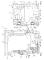
- figure 1 is a schematised longitudinal sectional view of a drying machine in a first embodiment
- figure 2 is a schematised transverse section view on several levels of the drying machine in figure 1;
- figure 3 is a schematised longitudinal sectional view on several levels of a drying machine according to the invention in a second embodiment
- figure 4 is a schematised transverse sectional view on several levels of the drying machine in figure 3;
- figure 5 is a sectional view of a detail of the drying machine in figures 3 and 4;
- figure 6 is a sectional view of a detail of the drying machine in figures 1 and 2;
- a laundry drying machine 1 comprises a casing 2 inside which is located a basket or drum 3 for housing the laundry.
- the basket 3 is provided with an inlet aperture 4 for a drying airflow 5 and an outlet aperture 6 for the moist air 7.
- Said apertures are communicating with a system of pipes with associated ventilator means, such as a ventilator rotor 8 driven by an electric motor 9, to convey the drying airflow 5, through the inlet aperture 4 in to the basket 3 and remove the moist air 7 from the latter through the outlet aperture 6.
- Suitable heating means being in a heat-exchange relationship with the drying air 5 are also provided, such as a electrical resistance 10, arranged in the airflow 5 upstream from the inlet aperture 4 and suitable to heat the air 5 before it enters the basket 3.
- Condenser means such as a heat exchanger, are associated to the abovementioned system of piping and suitable to dehumidify the moist air 7 removed from the basket 3.
- the laundry drying machine 1 further comprises means for moving the basket 3 in such a way to turn and spin the laundry, exposing it to the drying airflow 5.
- Such means comprise, for example an electric motor (not shown) causing the basket 3 to rotate, preferably with an alternating sense of direction.
- the system of piping comprises a suction mouth 11 for withdrawing environment air 12 from outside the casing 1 and a release mouth 13 for the expulsion of air into the environment and it defines or provides inside the casing 1:
- commutation means 18, 19 are provided, suitable to convert, selectively, said system of piping in said first and second circuit.
- said commutation means make it possible to operate the drying machine, selectively, by said open circuit or by said closed circuit.
- the commutation means can be adjusted so as to enable the operation of the drying machine simultaneously by said open circuit and said closed circuit, wherein the relationship between the flow rate in the open circuit and that in the closed circuit is preferably adjustable and settable as desired.
- the system of piping comprises an air removal tube 14 in fluid communication with the outlet aperture 6 of the basket 3, a delivery pipe 15 in fluid communication with the inlet aperture 4 of the basket 3, a suction pipe 16 in fluid communication with the suction mouth 11 and a release pipe 17 in fluid communication with the release mouth 13.
- the air removal pipe 14 is put in fluid communication with the delivery pipe 15 by the interposition of a delivery flow regulator 18, suitable to regulate the aperture of flow between the air removal pipe 14 and that of delivery 15 and the air removal pipe 14 is put in fluid communication with the release pipe 17 by the interposition of a release flow regulator 19, suitable to regulate the flow aperture between the air removal pipe 14 and that of release 17.
- the delivery pipe 15 on the other hand is put in fluid communication with the suction pipe 16 by the interposition of a suction flow regulator 18 suitable to regulate the flow aperture between the suction pipe 16 and that of delivery 15.
- the abovementioned delivery 18, suction 18 and release 19 flow regulators can be operated independently of one another or in dependence of one another by manual activation, such as by one or more handles or levers 32, or by suitable automatic activation means, such as one or more electric activation motors (not shown in figures).
- the delivery flow regulator 18 and the suction flow regulator 18 are united in a single delivery flow deviator device 18, suitable to put the delivery pipe 15, as desired, into fluid connection with the air removal pipe 14 or with the suction pipe 16.
- the delivery flow deviator 18 is suitable to establish i.e. compose the airflow fed into the delivery pipe 15, thus adjusting the single flow rates of the airflows originating from the air removal 14 and suction 16 pipes.
- a single deviator (not shown in the figures) is provided, suitable to compose the airflow fed into the delivery pipe 15 by regulating the single flow rates of the airflows originating from the air removal 14 and suction 16 pipes, wherein said deviator is further suitable to deviate directly into the release pipe 17 that portion of the airflow of the air removal pipe 14 that is not fed into the delivery pipe 15.
- the condenser means are comprises a heat exchanger 20, 21, 22 arranged in the pathway of the air removal pipe 14 that preferably forms the casing thereof.
- the heating resistance 10 is arranged in the pathway of the delivery pipe 15, preferably lodged inside thereof.
- the tank 21 serves both as a container for the cold water of the water supply that cools the air removed from the basket 3 condensing the moisture thereof, and as a collection tank for the condensation itself.
- a drain 25 is provided associated to suitable drainage means, such as a pump 26, suitable to drain, preferably in a sequential or intermittent way part or all of the liquid contained in the tank 21 to maintain or restrict the abovementioned maximum water level 24.
- suitable drainage means such as a pump 26, suitable to drain, preferably in a sequential or intermittent way part or all of the liquid contained in the tank 21 to maintain or restrict the abovementioned maximum water level 24.
- the air removal pipe 14 in particular a portion thereof arranged downstream from the condensation chamber 20, seen in the direction of the airflow, outlets into said delivery commutator 18 which in turn has, in addition to the fluid connection with the air removal pipe 14, a fluid connection with the delivery pipe 15 and one with the suction pipe 16.
- the delivery commutator 18 comprises a preferably cylindrical or conical casing 27 fitted with three apertures 28, 29, 30 made in different positions that make the three connections mentioned above, and a shutter element 31, also with an at least partially cylindrical or conical form, held in a swivelling way inside the casing 27.
- the shutter element 31, according to the angular position thereof in relation to the casing 27 of the delivery commutator 18, is suitable to regulate respectively the opening and closure of the fluid connections (apertures 28, 29, 30) of the delivery commutator 18 with the suction 16 and air removal pipes 14 and to deviate the respective airflows in the delivery pipe 15.
- the delivery pipe 15 extends from the delivery commutator 18 to the inlet aperture 4 of the basket 3.
- the rotor 8 is arranged and, preferably, the axis of rotation of the motor 9 and of the rotor 8 coincide with the axis of rotation of shutter adjustment 31.
- the heating resistance 10 is arranged in the delivery pipe 15 downstream from the rotor 8 seen in the direction of the airflow.
- the suction pipe 16 formed by a special plastic tube or by suitable spaces made inside the casing 2 of the drying machine 1 extends from the suction mouth 11 (that can be made as a single aperture, grid or by a number of apertures in the casing 2) until the aperture 29 of the delivery commutator 18, making the supplying thereof with fresh air 12 from the outside environment.
- the release pipe 17, formed by a special plastic tube or by suitable spaces made inside the casing 2 of the drying machine 1 extends from a flow regulator 19 connected with air removal pipe 14, preferably in a zone thereof down stream from the condensation chamber 20, until the release mouth 11 (that can be made for example as a single aperture, grid or number of apertures in the casing 2).
- the flow regulator 19 comprises a preferably cylindrical or conical casing fitted with two apertures that make the fluid communication between the air removal pipe 14 and the release pipe 17, and a shutter element, also with an at least partially cylindrical or conical form, held in a swivelling way inside the casing.
- the shutter element according to the angular position thereof in relation to the casing of the flow regulator, is suitable to regulate respectively the opening and closure of the fluid connection between the air removal 14 and release pipes 17, regulating the airflow released outside the drying machine 1.
- both the delivery commutator 18 and the release flow regulator 19 can be activated manually by special regulation levers 32.
- the delivery commutator 18 and the release flow regulator 19 can be automatically activated by special activation means, such as one or more regulation motors that can be controlled by a control unit of the drying machine 1.
- the environment air is sucked through the suction mouth 11 and conveyed by the rotor 8 along the suction pipe 16, through the delivery commutator 18 into the delivery pipe 15, inside which the air is heated by the resistance 10 before entering the basket 2 where it causes the evaporation of the moisture contained in the laundry.
- the moist air is removed from the basket 2 through the outlet aperture 6 and conveyed along the air removal pipe 14, through the open flow regulator 19 into the release pipe 17 and, through the release mouth 13, it is released outside the drying machine 1.
- the delivery commutator 18 prevents the suction of air from the air removal pipe 14 into the delivery pipe 15, as can be shown for example by figure 6.
- Cool water withdrawn from the water supply, is fed by the nebuliser nozzle 22 directly into the air removal pipe 14 forming inside thereof, in particular in the condensation chamber 20, a cold mist and it is collected in the tank 21 forming a cold water surface that substantially interests the entire widened zone of the air removal pipe 14, in other words, all of the condensation chamber 20.
- the moist air by passing through the condensation chamber 20, is cooled by both the cold mist and the cold water surface and, by condensing the moisture, it is dehumidified.
- the condensation is collected in the tank 21 that contains the cooling water and is released together with the latter in a sequential way outside the drying machine 1.
- the dehumidified air is conveyed by the air removal pipe 14, through the delivery commutator 18, into the delivery pipe 15, where it is once again heated by the resistance 10 before being reintroduced into the basket 2.
- the delivery commutator 18 prevents both the suction of air by the suction pipe 16 into the delivery pipe 15 and the release of the air from the air removal pipe 14 into the release pipe 17, as is shown for example by figures 4 and 5.
- the drying machine can be easily commutated by the activation of the levers 32, to hybrid operation, wherein the delivery flow sucked into the delivery pipe 15 is composed, by the delivery commutator 18, of two flows of controlled flow rates.
- a first flow consists in environment air sucked from outside the drying machine 1 through the suction pipe 16 and a second flow consists in recycled dehumidified air sucked from the air removal pipe 14. The excess air in the air removal pipe 14 is released, through the release pipe 17, to the outside of the drying machine.
- the filter 33 is inserted and extends along the stretch 14 of the vertical flow path and the stretch of the same flow path forms at least partially the condensation chamber 20 and the water collection tank 21.
- the invention can be implemented with advantage in both front-loading and top loading laundry dryer and washer-dryer machines.
- the invention achieves considerable advantages.
- the dehumidifier means 20, 21, 24, 25, 26, i.e. the condensation system is normally deactivated but can also be activated, for example, in a controlled way by means of the control unit of the drying machine, in order to lower in a controlled way, the charge of moisture in the air released into the environment.
- the laundry drying machine has a very simple and sturdy structure, wherein the majority of the components serves a function in both the open circuit and closed circuit configuration.
- the closed circuit 14, 15 forms a portion of the open circuit 14, 15, 16, 17, i.e., both circuits have the delivery pipe 14 and the air removal pipe 14 in common. This makes the manufacture and maintenance of the apparatus easier and cheaper.
- the drying machine is easily adaptable to different environments of installation and it provides high drying performance, using to the maximum the ability of the environment of installation to dispose of moisture.
- the drying machine also enables, during production, to define through an adjustment operation, that is negligible from the point of view of the costs of production, the type of drying system - open or closed - of the final product.
Landscapes
- Engineering & Computer Science (AREA)
- Textile Engineering (AREA)
- Detail Structures Of Washing Machines And Dryers (AREA)
- Control Of Washing Machine And Dryer (AREA)
- Drying Of Solid Materials (AREA)
Priority Applications (3)
| Application Number | Priority Date | Filing Date | Title |
|---|---|---|---|
| EP04425051.2A EP1559828B1 (de) | 2004-01-28 | 2004-01-28 | Verbesserter Wäschetrockner |
| DE602004010877T DE602004010877T2 (de) | 2004-01-28 | 2004-07-21 | Trockungsverfahren und Wäschetrockner |
| EP04017167A EP1559829B1 (de) | 2004-01-28 | 2004-07-21 | Trockungsverfahren und Wäschetrockner |
Applications Claiming Priority (1)
| Application Number | Priority Date | Filing Date | Title |
|---|---|---|---|
| EP04425051.2A EP1559828B1 (de) | 2004-01-28 | 2004-01-28 | Verbesserter Wäschetrockner |
Publications (2)
| Publication Number | Publication Date |
|---|---|
| EP1559828A1 true EP1559828A1 (de) | 2005-08-03 |
| EP1559828B1 EP1559828B1 (de) | 2014-06-25 |
Family
ID=34639513
Family Applications (2)
| Application Number | Title | Priority Date | Filing Date |
|---|---|---|---|
| EP04425051.2A Expired - Lifetime EP1559828B1 (de) | 2004-01-28 | 2004-01-28 | Verbesserter Wäschetrockner |
| EP04017167A Expired - Lifetime EP1559829B1 (de) | 2004-01-28 | 2004-07-21 | Trockungsverfahren und Wäschetrockner |
Family Applications After (1)
| Application Number | Title | Priority Date | Filing Date |
|---|---|---|---|
| EP04017167A Expired - Lifetime EP1559829B1 (de) | 2004-01-28 | 2004-07-21 | Trockungsverfahren und Wäschetrockner |
Country Status (2)
| Country | Link |
|---|---|
| EP (2) | EP1559828B1 (de) |
| DE (1) | DE602004010877T2 (de) |
Families Citing this family (9)
| Publication number | Priority date | Publication date | Assignee | Title |
|---|---|---|---|---|
| US7525262B2 (en) | 2005-01-12 | 2009-04-28 | Whirlpool Corporation | Automatic clothes dryer |
| DE102006016294A1 (de) * | 2006-04-06 | 2007-10-11 | BSH Bosch und Siemens Hausgeräte GmbH | Hausgerät zur Pflege von Wäschestücken |
| JP2008220817A (ja) * | 2007-03-15 | 2008-09-25 | Sanyo Electric Co Ltd | 洗濯乾燥機 |
| DE102008014305A1 (de) * | 2008-03-14 | 2009-09-17 | BSH Bosch und Siemens Hausgeräte GmbH | Ablufttrockner mit Umluftanteil sowie Verfahren zu seinem Betrieb |
| DE102008043176B4 (de) * | 2008-10-24 | 2021-08-26 | BSH Hausgeräte GmbH | Trockner mit Wärmepumpe, Verfahren zu seinem Betrieb und Verfahren zur Klimatisierung eines Raumes |
| CN104514114B (zh) * | 2013-09-03 | 2017-10-27 | Lg电子株式会社 | 衣物处理设备 |
| GB2519185B (en) * | 2014-05-30 | 2015-09-30 | Dbk David & Baader Gmbh | A tumble dryer |
| KR102821260B1 (ko) * | 2020-03-04 | 2025-06-13 | 엘지전자 주식회사 | 의류처리장치 |
| CN114182510A (zh) * | 2021-12-31 | 2022-03-15 | 广东美的白色家电技术创新中心有限公司 | 干衣机控制方法、装置、干衣机及存储介质 |
Citations (3)
| Publication number | Priority date | Publication date | Assignee | Title |
|---|---|---|---|---|
| JPS59228897A (ja) * | 1983-06-10 | 1984-12-22 | 松下電器産業株式会社 | 衣類乾燥機 |
| FR2648484A1 (fr) * | 1989-06-16 | 1990-12-21 | Ciapem | Seche-linge a rejet differe de l'humidite |
| JP2000005493A (ja) * | 1998-06-19 | 2000-01-11 | Hitachi Ltd | 衣類乾燥機の乾燥運転制御装置 |
Family Cites Families (4)
| Publication number | Priority date | Publication date | Assignee | Title |
|---|---|---|---|---|
| US4549362A (en) * | 1982-01-19 | 1985-10-29 | Haried John C | Programmable air recirculator/mixer for a fabric dryer |
| JPH03254797A (ja) * | 1990-03-02 | 1991-11-13 | Hitachi Ltd | 衣類乾燥機 |
| IT1250380B (it) * | 1991-03-12 | 1995-04-07 | Zanussi Elettrodomestici | Macchina asciugabiancheria di tipo perfezionato |
| JP2002282595A (ja) * | 2001-03-26 | 2002-10-02 | Toto Ltd | 衣類乾燥装置 |
-
2004
- 2004-01-28 EP EP04425051.2A patent/EP1559828B1/de not_active Expired - Lifetime
- 2004-07-21 EP EP04017167A patent/EP1559829B1/de not_active Expired - Lifetime
- 2004-07-21 DE DE602004010877T patent/DE602004010877T2/de not_active Expired - Lifetime
Patent Citations (3)
| Publication number | Priority date | Publication date | Assignee | Title |
|---|---|---|---|---|
| JPS59228897A (ja) * | 1983-06-10 | 1984-12-22 | 松下電器産業株式会社 | 衣類乾燥機 |
| FR2648484A1 (fr) * | 1989-06-16 | 1990-12-21 | Ciapem | Seche-linge a rejet differe de l'humidite |
| JP2000005493A (ja) * | 1998-06-19 | 2000-01-11 | Hitachi Ltd | 衣類乾燥機の乾燥運転制御装置 |
Non-Patent Citations (1)
| Title |
|---|
| PATENT ABSTRACTS OF JAPAN vol. 2000, no. 04 31 August 2000 (2000-08-31) * |
Also Published As
| Publication number | Publication date |
|---|---|
| EP1559828B1 (de) | 2014-06-25 |
| EP1559829A1 (de) | 2005-08-03 |
| EP1559829B1 (de) | 2007-12-26 |
| DE602004010877T2 (de) | 2009-01-02 |
| DE602004010877D1 (de) | 2008-02-07 |
Similar Documents
| Publication | Publication Date | Title |
|---|---|---|
| CN102686792B (zh) | 用于烘干衣物的装置 | |
| CN102471986B (zh) | 用于干燥衣物的设备 | |
| CN103348053A (zh) | 用于干燥衣物的设备 | |
| CN102383294B (zh) | 衣物处理机 | |
| KR101436754B1 (ko) | 옷 건조시스템 | |
| US20090126414A1 (en) | Fabric treating machine | |
| US12221742B2 (en) | Tumble dryer | |
| EP2423376B1 (de) | Wäschebehandlungsmaschine | |
| CN102286872A (zh) | 一种带热泵烘干和除湿功能的洗衣干衣机 | |
| US20100132217A1 (en) | Dryer with recirculated air proportion and method for operation of same | |
| EP1559828B1 (de) | Verbesserter Wäschetrockner | |
| TW200636114A (en) | Washing and drying machine | |
| WO2014017004A1 (ja) | 衣類乾燥機 | |
| EP2412861B1 (de) | Maschine zum Waschen und Trocknen von Wäsche | |
| JP2007209526A (ja) | 衣類乾燥機 | |
| US3875681A (en) | Condenser apparatus | |
| US3859004A (en) | Condenser apparatus | |
| EP2123823B1 (de) | Haushaltswäschetrockner | |
| EP0816548B1 (de) | Zusatzvorrichtung zum Umwandeln des Trocknungskreislaufs einer mit offenem Trocknungskreislauf Haushaltwaschmaschine in einen geschlossenen Kreislauf mit Luftkondensation des Wasserdampfes | |
| EP2042646A1 (de) | Haushaltswäschetrockner | |
| KR102544464B1 (ko) | 의류처리장치 | |
| CN115852654A (zh) | 烘干设备的热泵烘干系统及烘干设备 | |
| CN211716729U (zh) | 一种卫生间用取暖除湿机 | |
| EP2014821B1 (de) | Wäschetrockner für den Haushalt | |
| EP2042643B1 (de) | Haushaltswäschetrockner mit Dampfgenerator |
Legal Events
| Date | Code | Title | Description |
|---|---|---|---|
| PUAI | Public reference made under article 153(3) epc to a published international application that has entered the european phase |
Free format text: ORIGINAL CODE: 0009012 |
|
| AK | Designated contracting states |
Kind code of ref document: A1 Designated state(s): AT BE BG CH CY CZ DE DK EE ES FI FR GB GR HU IE IT LI LU MC NL PT RO SE SI SK TR |
|
| AX | Request for extension of the european patent |
Extension state: AL LT LV MK |
|
| 17P | Request for examination filed |
Effective date: 20051121 |
|
| AKX | Designation fees paid |
Designated state(s): DE FR GB IT |
|
| 17Q | First examination report despatched |
Effective date: 20060628 |
|
| GRAP | Despatch of communication of intention to grant a patent |
Free format text: ORIGINAL CODE: EPIDOSNIGR1 |
|
| INTG | Intention to grant announced |
Effective date: 20131205 |
|
| GRAS | Grant fee paid |
Free format text: ORIGINAL CODE: EPIDOSNIGR3 |
|
| GRAA | (expected) grant |
Free format text: ORIGINAL CODE: 0009210 |
|
| AK | Designated contracting states |
Kind code of ref document: B1 Designated state(s): DE FR GB IT |
|
| RAP1 | Party data changed (applicant data changed or rights of an application transferred) |
Owner name: CANDY S.P.A. |
|
| REG | Reference to a national code |
Ref country code: GB Ref legal event code: FG4D |
|
| RIN1 | Information on inventor provided before grant (corrected) |
Inventor name: FUMAGALLI, SILVANO |
|
| REG | Reference to a national code |
Ref country code: DE Ref legal event code: R096 Ref document number: 602004045337 Country of ref document: DE Effective date: 20140814 |
|
| RAP2 | Party data changed (patent owner data changed or rights of a patent transferred) |
Owner name: CANDY S.P.A. |
|
| REG | Reference to a national code |
Ref country code: DE Ref legal event code: R097 Ref document number: 602004045337 Country of ref document: DE |
|
| PLBE | No opposition filed within time limit |
Free format text: ORIGINAL CODE: 0009261 |
|
| STAA | Information on the status of an ep patent application or granted ep patent |
Free format text: STATUS: NO OPPOSITION FILED WITHIN TIME LIMIT |
|
| 26N | No opposition filed |
Effective date: 20150326 |
|
| REG | Reference to a national code |
Ref country code: FR Ref legal event code: PLFP Year of fee payment: 13 |
|
| REG | Reference to a national code |
Ref country code: FR Ref legal event code: PLFP Year of fee payment: 14 |
|
| PGFP | Annual fee paid to national office [announced via postgrant information from national office to epo] |
Ref country code: FR Payment date: 20170130 Year of fee payment: 14 |
|
| PGFP | Annual fee paid to national office [announced via postgrant information from national office to epo] |
Ref country code: GB Payment date: 20170119 Year of fee payment: 14 |
|
| PGFP | Annual fee paid to national office [announced via postgrant information from national office to epo] |
Ref country code: IT Payment date: 20170112 Year of fee payment: 14 |
|
| PGFP | Annual fee paid to national office [announced via postgrant information from national office to epo] |
Ref country code: DE Payment date: 20170331 Year of fee payment: 14 |
|
| REG | Reference to a national code |
Ref country code: DE Ref legal event code: R119 Ref document number: 602004045337 Country of ref document: DE |
|
| GBPC | Gb: european patent ceased through non-payment of renewal fee |
Effective date: 20180128 |
|
| PG25 | Lapsed in a contracting state [announced via postgrant information from national office to epo] |
Ref country code: DE Free format text: LAPSE BECAUSE OF NON-PAYMENT OF DUE FEES Effective date: 20180801 Ref country code: FR Free format text: LAPSE BECAUSE OF NON-PAYMENT OF DUE FEES Effective date: 20180131 |
|
| REG | Reference to a national code |
Ref country code: FR Ref legal event code: ST Effective date: 20180928 |
|
| PG25 | Lapsed in a contracting state [announced via postgrant information from national office to epo] |
Ref country code: GB Free format text: LAPSE BECAUSE OF NON-PAYMENT OF DUE FEES Effective date: 20180128 |
|
| PG25 | Lapsed in a contracting state [announced via postgrant information from national office to epo] |
Ref country code: IT Free format text: LAPSE BECAUSE OF NON-PAYMENT OF DUE FEES Effective date: 20180128 |