EP1559818A1 - Rundstrickmaschine - Google Patents
Rundstrickmaschine Download PDFInfo
- Publication number
- EP1559818A1 EP1559818A1 EP04001384A EP04001384A EP1559818A1 EP 1559818 A1 EP1559818 A1 EP 1559818A1 EP 04001384 A EP04001384 A EP 04001384A EP 04001384 A EP04001384 A EP 04001384A EP 1559818 A1 EP1559818 A1 EP 1559818A1
- Authority
- EP
- European Patent Office
- Prior art keywords
- sinker
- yarn
- section
- sinkers
- inclined manner
- Prior art date
- Legal status (The legal status is an assumption and is not a legal conclusion. Google has not performed a legal analysis and makes no representation as to the accuracy of the status listed.)
- Granted
Links
Images





Classifications
-
- D—TEXTILES; PAPER
- D04—BRAIDING; LACE-MAKING; KNITTING; TRIMMINGS; NON-WOVEN FABRICS
- D04B—KNITTING
- D04B15/00—Details of, or auxiliary devices incorporated in, weft knitting machines, restricted to machines of this kind
- D04B15/06—Sinkers
-
- D—TEXTILES; PAPER
- D04—BRAIDING; LACE-MAKING; KNITTING; TRIMMINGS; NON-WOVEN FABRICS
- D04B—KNITTING
- D04B15/00—Details of, or auxiliary devices incorporated in, weft knitting machines, restricted to machines of this kind
- D04B15/66—Devices for determining or controlling patterns ; Program-control arrangements
- D04B15/80—Devices for determining or controlling patterns ; Program-control arrangements characterised by the thread guides used
-
- D—TEXTILES; PAPER
- D04—BRAIDING; LACE-MAKING; KNITTING; TRIMMINGS; NON-WOVEN FABRICS
- D04B—KNITTING
- D04B9/00—Circular knitting machines with independently-movable needles
- D04B9/12—Circular knitting machines with independently-movable needles with provision for incorporating pile threads
Definitions
- the present invention relates to a circular knitting machine and particularly to a circular knitting machine that has sinkers mounted in an inclined manner to position yarn laps and avoid hitting yarn feeding plates when moving in an inclined manner in sinker troughs.
- Conventional circular knitting machines generally include sinkers driven by a cam.
- the cam has a driving path to move the sinkers to and fro to perform knitting operation.
- the sinker is engaged with a preset driving path as shown in FIG. 1.
- the lug 62 of the sinker 61 is engaged with the driving path 64 of the cam 63 so that the sinker 61 is moved according to the driving path 64 to perform knitting operation.
- the cam 63 is mounted horizontally on the machine deck.
- the sinker 61 also is mounted horizontally.
- the sinker 61 is located on a sinker drum 60 which rotates at high speed during knitting operation, and the sinker 61 is driven by the driving path 64 to move reciprocally to and fro rapidly.
- the sinker drum 60 rotates at high speed, the sinker 61 is moved outwards at a great centrifugal force. Hence the lug 62 of the sinker 61 does not move smoothly in the driving path 64.
- Applicant has proposed an improved design that includes a sinker drum with a slant surface so that the cams and sinkers are mounted at an inclined angle against the horizontal surface.
- the sinkers may be moved in an inclined manner in the sinker troughs of the sinker drum thereby may be driven by the cams more smoothly.
- the slant installation set forth above can reduce the centrifugal force of the sinker that hits the cam and increase the service life of the sinker and the cam, it creates other problems, notably: first, with the sinker directly mounted on the sinker drum in an inclined manner, the surface for holding formed yarn laps on its throat portion also is inclined. As a result, the formed yarn laps tend to slip downwards and stretch the yarn coupled on the needle. Second, with the sinker inclined, the movement of the sinker in the sinker trough also is inclined. As a result, the sinker is prone to hit the yarn feeding plate. The circular knitting machine could become inoperable. The present invention aims to improve these problems.
- the object of the invention is to provide a circular knitting machine that has yarn feeding plates with a dodging edge and a slant surface formed on each of them to dodge the sinker that is moved in an inclined manner in the sinker drum, and the sinker has a throat section which has one side extended to form an inclined first end surface so that the nose section of the sinker can hold the yarn laps at a higher horizontal spot without slipping even though the sinker is moved in an inclined manner in the sinker drum.
- a cam 20 is fastened to a slant surface of a saddle plate (not shown in the drawing) mounted on a machine deck of a circular knitting machine and forms an inclined angle ⁇ against the horizontal surface.
- the cam 20 has a driving path 22 to allow a lug 21 of a sinker 10 to slide therein.
- the sinker 10 also is mounted in a slant manner to match the cam 20.
- the sinker 10 includes a belly section 11, a nose section 12 and a throat section 13.
- the throat section 13 has one end forming a first end surface 131.
- the belly section 11 has one end forming a second end surface 111.
- FIGS. 6 and 7 for another main element of the invention.
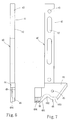
- a yarn feeding plate 40 has one end forming an elongated mounting section 41 which has two slots 42 and a screw hole 43 for fastening to the machine deck.
- the yarn feeding plate 40 has other end forming a polygonal yarn feeding section 44 which has a first yarn feeding port 45 and a second yarn feeding port 46 to allow knitting yarns to thread through for feeding.
- the yarn feeding section 44 has a dodging edge 48 on the bottom surface.
- the dodging edge 48 is an irregular and continuous curved surface designed according to the moving tracks of the sinker 10 in the driving path 22 of the cam 20 and aims to dodge the sinker 10.
- the dodging edge 48 has a slant surface 484 at the front edge to avoid hitting the sinker 10 when it is moved in the sinker drum 161 in an inclined manner.
- a pile yarn 17 is threaded through the first yarn feeding port 45, and a bottom yarn 18 is threaded through the second yarn feeding port 46.
- This paragraph aims to explain the release condition of a yarn lap 17a.
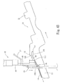
- the sinker 10 is moved in an inclined manner towards the circular center of the circular knitting machine (not shown in the drawings) until reaching a lower dead point (referring to FIG. 4A); meanwhile a needle 15 is lifted fully, and a tie yarn 19 is sunk to the root section of the needle 15; then the sinker 10 is moved rearwards in an inclined manner until reaching an upper dead point (referring to FIG.
- the needle 15 is lowered to one half, and the yarn lap 17a escapes the nose section 12 of the sinker 10 and drops onto the second end surface 111 of the belly section 11, and is pulled downwards by the formed and coupled laps 14 in the front to become a release condition; the bottom yarn 18 also drops onto the second end surface 111 of the sinker 10; meanwhile the pile yarn 17 in the first yarn feeding port 45 is pulled downwards by the needle 15.
- the sinker 10 is moved slowly towards the circular center of the knitting machine (not shown in the drawings); the throat section 13 of the sinker 10 (also referring to FIG. 2) picks up the bottom yarn 18; the first end surface 131 of the throat section 131 compresses the formed laps 14 so that they do not float and hinder knitting operation.
- the sinker 10 is moved slightly forwards, and the needle 15 is moved downwards to the lower dead point; meanwhile the needle 15 pulls the pile yarn 17 downwards and picks up the bottom yarn 18; then the tie yarn 19 is moved upwards from the root section of the needle 15 to close the latch 151 of the needle 15; the tie yarn 19 passes over the periphery of the needle 15 to wrap the pile yarn 17 and the bottom yarn 18 (referring to FIG. 4D); the nose section 12 holds the yarn lap 17a at a high horizontal spot to prevent the yarn lap 17a from slipping down.
- the needle withdrawing and lap forming process is complete the needle withdrawing and lap forming process.
- the sinker 10 is moved rearwards slightly (in a direction shown by the arrow); the needle 15 is lifted slightly to slightly loosen the yarn lap 17a; meanwhile the yarn lap 17a drops from the top end of the nose section 12 to a bracing point 121; finally the needle 15 is lifted, and the sinker 10 is moved forwards to lift the yarn lap 17a; the tie yarn 19 drops to the root section of the needle 15.
- the processes set forth may be repeatedly performed to knit a single-face counter-wrapped pile fabric.
- the dodging edge 48 on the distal end of the yarn feeding plate 40 is formed in a shape according to the movement track of the sinker 10 in the driving path 22 of the cam 20.
- the slant surface 484 on the front side of the dodge edge 48 is formed to avoid hitting the sinker 10 when it is moved in an inclined manner in the sinker trough 161.
- the dodging edge 48 is formed in an irregular and continuous curved surface as previously mentioned. It includes a first position 481, a second position 482 and a third position 483.
- the movement relationship of the yarn feeding plate 40 and the sinker 10 is elaborated as follow:
- the sinker 10 is mounted on a sinker drum 16 which is located on an inner annular ring of the circular knitting machine, and is formed in the shape of a conical and shallow tray.
- the sinker drum 16 has sinker troughs 161 formed on the perimeter in an equally spaced fashion to house the sinkers 10.
- the sinker drum 16 is rotated at high speed during knitting operation to drive the sinker 10 to turn at high speed.
- the sinker 10 while the sinker 10 is turning, it also is driven by the driving path 22 of the cam 20 and moved to and fro reciprocally.
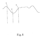
- the movement track of the sinker 10 is determined by the driving path 22 as shown in FIG. 8, which illustrates the track according to time sequence.
- the irregular and continuous curved surface of the dodging edge 48 of the yarn feeding plate 40 is determined by the movement track of the sinker 10.
- the dodging edge 48 of the yarn feeding plate 40 aims to match the movement track of the sinker 10 to prevent such interference.
- the sinker 10 is located at the front most end (i.e. first point 1 in the time sequence chart shown in FIG. 8).
- the yarn feeding plate 40 has a matching concave surface of the first position 481.
- the sinker 10 is driven by the driving path 22 and moved backwards (in the direction shown by the arrow, at second point 2 in the time sequence chart in FIG. 8) until reaching to the rear most position; the sinker 10 is at the lowest point.
- the yarn feeding plate 40 is at the second position 482.
- the irregular and continuous curved surface of the dodging edge 48 has a track same as the one from the first point 1 to the second point 2 in the time sequence chart. Therefore it can avoid hitting the sinker 10 during the to and fro movement and prevent interference.
- the driving path 22 drives the sinker 10 to move forwards in an inclined manner (also indicated by the arrow direction); the third position 483 of the dodging edge 48 can dodge the sinker 10, and the irregular and continuous curved surface of the dodging edge 48 has a track same as the one moving to the third point 3 in the time sequence chart. Therefore it can avoid hitting the sinker 10 during the to and fro movement and prevent interference.
- the shape of the dodging edge 48 of the yarn feeding plate 40 is formed according to the movement track of the sinker 10.
- the entire irregular and continuous curved surface of the dodging edge 48 also forms an inclined surface 484 at the distal end to match the slant installation of the sinker 10 on the sinker drum 16. Thereby the continuous rotation of the sinker 10 that also is moved in an inclined manner in the sinker trough 161 does not hit the inclined surface 484 at the front end of the dodging edge 48.
Landscapes
- Engineering & Computer Science (AREA)
- Textile Engineering (AREA)
- Knitting Machines (AREA)
Priority Applications (5)
| Application Number | Priority Date | Filing Date | Title |
|---|---|---|---|
| US10/759,427 US7152436B2 (en) | 2004-01-20 | 2004-01-20 | Circular knitting machine |
| AT04001384T ATE358739T1 (de) | 2004-01-20 | 2004-01-22 | Rundstrickmaschine |
| ES04001384T ES2285279T3 (es) | 2004-01-20 | 2004-01-22 | Maquina de tejer circular. |
| EP04001384A EP1559818B1 (de) | 2004-01-20 | 2004-01-22 | Rundstrickmaschine |
| DE602004005661T DE602004005661T2 (de) | 2004-01-20 | 2004-01-22 | Rundstrickmaschine |
Applications Claiming Priority (2)
| Application Number | Priority Date | Filing Date | Title |
|---|---|---|---|
| US10/759,427 US7152436B2 (en) | 2004-01-20 | 2004-01-20 | Circular knitting machine |
| EP04001384A EP1559818B1 (de) | 2004-01-20 | 2004-01-22 | Rundstrickmaschine |
Publications (2)
| Publication Number | Publication Date |
|---|---|
| EP1559818A1 true EP1559818A1 (de) | 2005-08-03 |
| EP1559818B1 EP1559818B1 (de) | 2007-04-04 |
Family
ID=34889005
Family Applications (1)
| Application Number | Title | Priority Date | Filing Date |
|---|---|---|---|
| EP04001384A Expired - Lifetime EP1559818B1 (de) | 2004-01-20 | 2004-01-22 | Rundstrickmaschine |
Country Status (5)
| Country | Link |
|---|---|
| US (1) | US7152436B2 (de) |
| EP (1) | EP1559818B1 (de) |
| AT (1) | ATE358739T1 (de) |
| DE (1) | DE602004005661T2 (de) |
| ES (1) | ES2285279T3 (de) |
Cited By (2)
| Publication number | Priority date | Publication date | Assignee | Title |
|---|---|---|---|---|
| CN105463688A (zh) * | 2016-01-06 | 2016-04-06 | 福建省鑫港纺织机械有限公司 | 一种所有梳栉全部成圈的经编机 |
| CN107429450A (zh) * | 2015-01-28 | 2017-12-01 | 耐克创新有限合伙公司 | 具有用于致动沉降片的偏压凸轮构件的针织机 |
Families Citing this family (5)
| Publication number | Priority date | Publication date | Assignee | Title |
|---|---|---|---|---|
| US7607322B1 (en) * | 2008-12-17 | 2009-10-27 | Monarch Knitting Machinery Corp. | Circular knitting machine with sinker cams facilitating high-speed operation |
| JP5987180B2 (ja) * | 2012-02-15 | 2016-09-07 | 岡本株式会社 | パイル長を変化できる編機及びパイル長を変化させた編地の製造方法 |
| CN103255562B (zh) * | 2012-02-15 | 2015-11-25 | 冈本株式会社 | 线圈尺寸可控的针织机及针织面料的制造方法 |
| US8938995B2 (en) | 2013-03-15 | 2015-01-27 | Monarch Knitting Machinery Corporation | Circular knitting machine with mounting arrangement for sinker cams |
| IT201800007018A1 (it) * | 2018-07-06 | 2020-01-06 | Metodo di realizzazione di un punto maglia in una macchina di maglieria a una o più cadute |
Citations (5)
| Publication number | Priority date | Publication date | Assignee | Title |
|---|---|---|---|---|
| GB1307502A (de) * | 1970-01-16 | 1973-02-21 | Elitex Formation Of Loops In C | |
| EP0351935A2 (de) * | 1988-07-20 | 1990-01-24 | Precision Fukuhara Works, Ltd | Rundstrickmaschine zum Stricken eines Tuches |
| FR2639659A1 (fr) * | 1988-11-29 | 1990-06-01 | Lu Sa Ho | Procede de tricotage |
| EP0402034A1 (de) * | 1989-05-31 | 1990-12-12 | Precision Fukuhara Works, Ltd | Doppelgestrick-Rundstrickmaschine |
| EP0478855A1 (de) * | 1990-10-04 | 1992-04-08 | Precision Fukuhara Works, Ltd | Verfahren zum Stricken von einem Stoff und Rundstrickmaschine zur Durchführung davon |
Family Cites Families (9)
| Publication number | Priority date | Publication date | Assignee | Title |
|---|---|---|---|---|
| US2775109A (en) * | 1954-04-13 | 1956-12-25 | Scarborough Frederick | Yarn carrier tube for knitting machines |
| US3444704A (en) * | 1968-01-29 | 1969-05-20 | Marvel Specialty Co Inc | Throat plate |
| US3837185A (en) * | 1970-01-16 | 1974-09-24 | I Musil | Method and apparatus for forming loops in circular knitting machines |
| US3986371A (en) * | 1970-01-16 | 1976-10-19 | Elitex, Zavody Textilniho Strojirenstvi Generalni Reditalstvi | Method for forming loops in circular knitting machines |
| US3826110A (en) * | 1972-04-03 | 1974-07-30 | Oakdale Knitting Co | Yarn feeding and control means for circular knitting machine |
| ES459450A1 (es) * | 1977-06-03 | 1978-04-01 | Jumberca Sa | Perfeccionamientos en la obtencion de un tejido de rizo a una sola cara en genero de punto. |
| JP2767273B2 (ja) * | 1989-03-13 | 1998-06-18 | 株式会社福原精機製作所 | プレーティングパイル編地の製造方法およびこれに使用するシンカー |
| US6799444B1 (en) * | 2004-01-20 | 2004-10-05 | Pai Lung Machinery Mill Co., Ltd. | Circular knitting machine |
| US6840065B1 (en) * | 2004-01-20 | 2005-01-11 | Pai Lung Machinery Mill Co., Ltd. | Sinker of circular knitting machines for pile fabrics |
-
2004
- 2004-01-20 US US10/759,427 patent/US7152436B2/en not_active Expired - Fee Related
- 2004-01-22 EP EP04001384A patent/EP1559818B1/de not_active Expired - Lifetime
- 2004-01-22 AT AT04001384T patent/ATE358739T1/de not_active IP Right Cessation
- 2004-01-22 DE DE602004005661T patent/DE602004005661T2/de not_active Expired - Lifetime
- 2004-01-22 ES ES04001384T patent/ES2285279T3/es not_active Expired - Lifetime
Patent Citations (5)
| Publication number | Priority date | Publication date | Assignee | Title |
|---|---|---|---|---|
| GB1307502A (de) * | 1970-01-16 | 1973-02-21 | Elitex Formation Of Loops In C | |
| EP0351935A2 (de) * | 1988-07-20 | 1990-01-24 | Precision Fukuhara Works, Ltd | Rundstrickmaschine zum Stricken eines Tuches |
| FR2639659A1 (fr) * | 1988-11-29 | 1990-06-01 | Lu Sa Ho | Procede de tricotage |
| EP0402034A1 (de) * | 1989-05-31 | 1990-12-12 | Precision Fukuhara Works, Ltd | Doppelgestrick-Rundstrickmaschine |
| EP0478855A1 (de) * | 1990-10-04 | 1992-04-08 | Precision Fukuhara Works, Ltd | Verfahren zum Stricken von einem Stoff und Rundstrickmaschine zur Durchführung davon |
Cited By (3)
| Publication number | Priority date | Publication date | Assignee | Title |
|---|---|---|---|---|
| CN107429450A (zh) * | 2015-01-28 | 2017-12-01 | 耐克创新有限合伙公司 | 具有用于致动沉降片的偏压凸轮构件的针织机 |
| CN107429450B (zh) * | 2015-01-28 | 2019-10-15 | 耐克创新有限合伙公司 | 具有用于致动沉降片的偏压凸轮构件的针织机 |
| CN105463688A (zh) * | 2016-01-06 | 2016-04-06 | 福建省鑫港纺织机械有限公司 | 一种所有梳栉全部成圈的经编机 |
Also Published As
| Publication number | Publication date |
|---|---|
| EP1559818B1 (de) | 2007-04-04 |
| US7152436B2 (en) | 2006-12-26 |
| DE602004005661T2 (de) | 2007-12-27 |
| DE602004005661D1 (de) | 2007-05-16 |
| US20050155391A1 (en) | 2005-07-21 |
| ATE358739T1 (de) | 2007-04-15 |
| ES2285279T3 (es) | 2007-11-16 |
Similar Documents
| Publication | Publication Date | Title |
|---|---|---|
| JP4025512B2 (ja) | 靴下のつま先縫製方法と装置 | |
| EP1559818B1 (de) | Rundstrickmaschine | |
| GB2372511A (en) | Circular knitting machine for knitting double-faced pile fabric | |
| US5010744A (en) | Method of constructing plating pile knit fabric and sinker therefor | |
| US4005589A (en) | Knitting elements | |
| JP5337445B2 (ja) | ミシン及びミシン用フックシステム | |
| US3086486A (en) | Button feeder | |
| US4576018A (en) | Stitch-forming machine | |
| US3215105A (en) | Rotary hook for sewing machines | |
| KR100777604B1 (ko) | 원형 편물기 | |
| US6189469B1 (en) | Strip matter cutting device for sewing machine | |
| JPH0299647A (ja) | サーキュラ編み機 | |
| CN219410149U (zh) | 一种旋梭梭架、旋梭结构及其缝纫机 | |
| US4489899A (en) | Yarn feeding apparatus for multi-feed knitting machines | |
| CN202247300U (zh) | 缝纫机的弯针装置 | |
| US3488679A (en) | Yarn severing device for circular knitting machine | |
| EP0351935B1 (de) | Rundstrickmaschine zum Stricken eines Tuches | |
| KR200424235Y1 (ko) | 직물용환편기 | |
| JP2736384B2 (ja) | 丸編機によるダブルフリース編地の製造方法 | |
| US4487142A (en) | Bobbin case chain stitch insert | |
| CN215628559U (zh) | 一种横机山板的筒口三角 | |
| JP3078829B2 (ja) | 丸編機によるプレーティング編地の製造方法 | |
| GB2100297A (en) | Yarn gripping and cutting device in circular knitting machine for producing open fabric | |
| KR20130072515A (ko) | 직물용환편기 | |
| US5492072A (en) | Half-turn hook with loop positioning surfaces |
Legal Events
| Date | Code | Title | Description |
|---|---|---|---|
| PUAI | Public reference made under article 153(3) epc to a published international application that has entered the european phase |
Free format text: ORIGINAL CODE: 0009012 |
|
| AK | Designated contracting states |
Kind code of ref document: A1 Designated state(s): AT BE BG CH CY CZ DE DK EE ES FI FR GB GR HU IE IT LI LU MC NL PT RO SE SI SK TR |
|
| AX | Request for extension of the european patent |
Extension state: AL LT LV MK |
|
| 17P | Request for examination filed |
Effective date: 20051019 |
|
| AKX | Designation fees paid |
Designated state(s): AT BE BG CH CY CZ DE DK EE ES FI FR GB GR HU IE IT LI LU MC NL PT RO SE SI SK TR |
|
| GRAP | Despatch of communication of intention to grant a patent |
Free format text: ORIGINAL CODE: EPIDOSNIGR1 |
|
| GRAS | Grant fee paid |
Free format text: ORIGINAL CODE: EPIDOSNIGR3 |
|
| GRAA | (expected) grant |
Free format text: ORIGINAL CODE: 0009210 |
|
| AK | Designated contracting states |
Kind code of ref document: B1 Designated state(s): AT BE BG CH CY CZ DE DK EE ES FI FR GB GR HU IE IT LI LU MC NL PT RO SE SI SK TR |
|
| PG25 | Lapsed in a contracting state [announced via postgrant information from national office to epo] |
Ref country code: CH Free format text: LAPSE BECAUSE OF FAILURE TO SUBMIT A TRANSLATION OF THE DESCRIPTION OR TO PAY THE FEE WITHIN THE PRESCRIBED TIME-LIMIT Effective date: 20070404 Ref country code: LI Free format text: LAPSE BECAUSE OF FAILURE TO SUBMIT A TRANSLATION OF THE DESCRIPTION OR TO PAY THE FEE WITHIN THE PRESCRIBED TIME-LIMIT Effective date: 20070404 Ref country code: FI Free format text: LAPSE BECAUSE OF FAILURE TO SUBMIT A TRANSLATION OF THE DESCRIPTION OR TO PAY THE FEE WITHIN THE PRESCRIBED TIME-LIMIT Effective date: 20070404 Ref country code: SI Free format text: LAPSE BECAUSE OF FAILURE TO SUBMIT A TRANSLATION OF THE DESCRIPTION OR TO PAY THE FEE WITHIN THE PRESCRIBED TIME-LIMIT Effective date: 20070404 |
|
| REG | Reference to a national code |
Ref country code: GB Ref legal event code: FG4D |
|
| REG | Reference to a national code |
Ref country code: CH Ref legal event code: EP |
|
| REF | Corresponds to: |
Ref document number: 602004005661 Country of ref document: DE Date of ref document: 20070516 Kind code of ref document: P |
|
| REG | Reference to a national code |
Ref country code: IE Ref legal event code: FG4D |
|
| PG25 | Lapsed in a contracting state [announced via postgrant information from national office to epo] |
Ref country code: SE Free format text: LAPSE BECAUSE OF FAILURE TO SUBMIT A TRANSLATION OF THE DESCRIPTION OR TO PAY THE FEE WITHIN THE PRESCRIBED TIME-LIMIT Effective date: 20070704 |
|
| PG25 | Lapsed in a contracting state [announced via postgrant information from national office to epo] |
Ref country code: PT Free format text: LAPSE BECAUSE OF FAILURE TO SUBMIT A TRANSLATION OF THE DESCRIPTION OR TO PAY THE FEE WITHIN THE PRESCRIBED TIME-LIMIT Effective date: 20070904 |
|
| NLV1 | Nl: lapsed or annulled due to failure to fulfill the requirements of art. 29p and 29m of the patents act | ||
| REG | Reference to a national code |
Ref country code: CH Ref legal event code: PL |
|
| REG | Reference to a national code |
Ref country code: ES Ref legal event code: FG2A Ref document number: 2285279 Country of ref document: ES Kind code of ref document: T3 |
|
| PG25 | Lapsed in a contracting state [announced via postgrant information from national office to epo] |
Ref country code: AT Free format text: LAPSE BECAUSE OF FAILURE TO SUBMIT A TRANSLATION OF THE DESCRIPTION OR TO PAY THE FEE WITHIN THE PRESCRIBED TIME-LIMIT Effective date: 20070404 |
|
| EN | Fr: translation not filed | ||
| PG25 | Lapsed in a contracting state [announced via postgrant information from national office to epo] |
Ref country code: BE Free format text: LAPSE BECAUSE OF FAILURE TO SUBMIT A TRANSLATION OF THE DESCRIPTION OR TO PAY THE FEE WITHIN THE PRESCRIBED TIME-LIMIT Effective date: 20070404 |
|
| PG25 | Lapsed in a contracting state [announced via postgrant information from national office to epo] |
Ref country code: CZ Free format text: LAPSE BECAUSE OF FAILURE TO SUBMIT A TRANSLATION OF THE DESCRIPTION OR TO PAY THE FEE WITHIN THE PRESCRIBED TIME-LIMIT Effective date: 20070404 Ref country code: BG Free format text: LAPSE BECAUSE OF FAILURE TO SUBMIT A TRANSLATION OF THE DESCRIPTION OR TO PAY THE FEE WITHIN THE PRESCRIBED TIME-LIMIT Effective date: 20070704 Ref country code: NL Free format text: LAPSE BECAUSE OF FAILURE TO SUBMIT A TRANSLATION OF THE DESCRIPTION OR TO PAY THE FEE WITHIN THE PRESCRIBED TIME-LIMIT Effective date: 20070404 Ref country code: DK Free format text: LAPSE BECAUSE OF FAILURE TO SUBMIT A TRANSLATION OF THE DESCRIPTION OR TO PAY THE FEE WITHIN THE PRESCRIBED TIME-LIMIT Effective date: 20070404 |
|
| PLBE | No opposition filed within time limit |
Free format text: ORIGINAL CODE: 0009261 |
|
| STAA | Information on the status of an ep patent application or granted ep patent |
Free format text: STATUS: NO OPPOSITION FILED WITHIN TIME LIMIT |
|
| PG25 | Lapsed in a contracting state [announced via postgrant information from national office to epo] |
Ref country code: SK Free format text: LAPSE BECAUSE OF FAILURE TO SUBMIT A TRANSLATION OF THE DESCRIPTION OR TO PAY THE FEE WITHIN THE PRESCRIBED TIME-LIMIT Effective date: 20070404 |
|
| 26N | No opposition filed |
Effective date: 20080107 |
|
| PG25 | Lapsed in a contracting state [announced via postgrant information from national office to epo] |
Ref country code: FR Free format text: LAPSE BECAUSE OF FAILURE TO SUBMIT A TRANSLATION OF THE DESCRIPTION OR TO PAY THE FEE WITHIN THE PRESCRIBED TIME-LIMIT Effective date: 20071130 Ref country code: GR Free format text: LAPSE BECAUSE OF FAILURE TO SUBMIT A TRANSLATION OF THE DESCRIPTION OR TO PAY THE FEE WITHIN THE PRESCRIBED TIME-LIMIT Effective date: 20070705 |
|
| PG25 | Lapsed in a contracting state [announced via postgrant information from national office to epo] |
Ref country code: RO Free format text: LAPSE BECAUSE OF FAILURE TO SUBMIT A TRANSLATION OF THE DESCRIPTION OR TO PAY THE FEE WITHIN THE PRESCRIBED TIME-LIMIT Effective date: 20070404 |
|
| PG25 | Lapsed in a contracting state [announced via postgrant information from national office to epo] |
Ref country code: MC Free format text: LAPSE BECAUSE OF NON-PAYMENT OF DUE FEES Effective date: 20080131 |
|
| GBPC | Gb: european patent ceased through non-payment of renewal fee |
Effective date: 20080122 |
|
| PG25 | Lapsed in a contracting state [announced via postgrant information from national office to epo] |
Ref country code: FR Free format text: LAPSE BECAUSE OF FAILURE TO SUBMIT A TRANSLATION OF THE DESCRIPTION OR TO PAY THE FEE WITHIN THE PRESCRIBED TIME-LIMIT Effective date: 20070404 |
|
| PG25 | Lapsed in a contracting state [announced via postgrant information from national office to epo] |
Ref country code: GB Free format text: LAPSE BECAUSE OF NON-PAYMENT OF DUE FEES Effective date: 20080122 |
|
| PG25 | Lapsed in a contracting state [announced via postgrant information from national office to epo] |
Ref country code: IE Free format text: LAPSE BECAUSE OF NON-PAYMENT OF DUE FEES Effective date: 20080122 Ref country code: EE Free format text: LAPSE BECAUSE OF FAILURE TO SUBMIT A TRANSLATION OF THE DESCRIPTION OR TO PAY THE FEE WITHIN THE PRESCRIBED TIME-LIMIT Effective date: 20070404 |
|
| PG25 | Lapsed in a contracting state [announced via postgrant information from national office to epo] |
Ref country code: CY Free format text: LAPSE BECAUSE OF FAILURE TO SUBMIT A TRANSLATION OF THE DESCRIPTION OR TO PAY THE FEE WITHIN THE PRESCRIBED TIME-LIMIT Effective date: 20070404 |
|
| PG25 | Lapsed in a contracting state [announced via postgrant information from national office to epo] |
Ref country code: HU Free format text: LAPSE BECAUSE OF FAILURE TO SUBMIT A TRANSLATION OF THE DESCRIPTION OR TO PAY THE FEE WITHIN THE PRESCRIBED TIME-LIMIT Effective date: 20071005 Ref country code: LU Free format text: LAPSE BECAUSE OF NON-PAYMENT OF DUE FEES Effective date: 20080122 |
|
| PGFP | Annual fee paid to national office [announced via postgrant information from national office to epo] |
Ref country code: DE Payment date: 20140131 Year of fee payment: 11 |
|
| PGFP | Annual fee paid to national office [announced via postgrant information from national office to epo] |
Ref country code: IT Payment date: 20140128 Year of fee payment: 11 Ref country code: TR Payment date: 20140103 Year of fee payment: 11 Ref country code: ES Payment date: 20140129 Year of fee payment: 11 |
|
| REG | Reference to a national code |
Ref country code: DE Ref legal event code: R119 Ref document number: 602004005661 Country of ref document: DE |
|
| PG25 | Lapsed in a contracting state [announced via postgrant information from national office to epo] |
Ref country code: DE Free format text: LAPSE BECAUSE OF NON-PAYMENT OF DUE FEES Effective date: 20150801 |
|
| PG25 | Lapsed in a contracting state [announced via postgrant information from national office to epo] |
Ref country code: IT Free format text: LAPSE BECAUSE OF NON-PAYMENT OF DUE FEES Effective date: 20150122 |
|
| REG | Reference to a national code |
Ref country code: ES Ref legal event code: FD2A Effective date: 20160226 |
|
| PG25 | Lapsed in a contracting state [announced via postgrant information from national office to epo] |
Ref country code: ES Free format text: LAPSE BECAUSE OF NON-PAYMENT OF DUE FEES Effective date: 20150123 |
|
| PG25 | Lapsed in a contracting state [announced via postgrant information from national office to epo] |
Ref country code: TR Free format text: LAPSE BECAUSE OF NON-PAYMENT OF DUE FEES Effective date: 20150122 |