EP1559670B1 - Cassette de média d'un distributeur de média automatique - Google Patents
Cassette de média d'un distributeur de média automatique Download PDFInfo
- Publication number
- EP1559670B1 EP1559670B1 EP04030968A EP04030968A EP1559670B1 EP 1559670 B1 EP1559670 B1 EP 1559670B1 EP 04030968 A EP04030968 A EP 04030968A EP 04030968 A EP04030968 A EP 04030968A EP 1559670 B1 EP1559670 B1 EP 1559670B1
- Authority
- EP
- European Patent Office
- Prior art keywords
- media
- connection
- base plate
- support
- guide
- Prior art date
- Legal status (The legal status is an assumption and is not a legal conclusion. Google has not performed a legal analysis and makes no representation as to the accuracy of the status listed.)
- Active
Links
Images


Classifications
-
- G—PHYSICS
- G07—CHECKING-DEVICES
- G07F—COIN-FREED OR LIKE APPARATUS
- G07F19/00—Complete banking systems; Coded card-freed arrangements adapted for dispensing or receiving monies or the like and posting such transactions to existing accounts, e.g. automatic teller machines
-
- B—PERFORMING OPERATIONS; TRANSPORTING
- B65—CONVEYING; PACKING; STORING; HANDLING THIN OR FILAMENTARY MATERIAL
- B65H—HANDLING THIN OR FILAMENTARY MATERIAL, e.g. SHEETS, WEBS, CABLES
- B65H1/00—Supports or magazines for piles from which articles are to be separated
- B65H1/02—Supports or magazines for piles from which articles are to be separated adapted to support articles on edge
-
- G—PHYSICS
- G07—CHECKING-DEVICES
- G07D—HANDLING OF COINS OR VALUABLE PAPERS, e.g. TESTING, SORTING BY DENOMINATIONS, COUNTING, DISPENSING, CHANGING OR DEPOSITING
- G07D11/00—Devices accepting coins; Devices accepting, dispensing, sorting or counting valuable papers
- G07D11/10—Mechanical details
- G07D11/12—Containers for valuable papers
-
- B—PERFORMING OPERATIONS; TRANSPORTING
- B65—CONVEYING; PACKING; STORING; HANDLING THIN OR FILAMENTARY MATERIAL
- B65H—HANDLING THIN OR FILAMENTARY MATERIAL, e.g. SHEETS, WEBS, CABLES
- B65H2301/00—Handling processes for sheets or webs
- B65H2301/40—Type of handling process
- B65H2301/42—Piling, depiling, handling piles
- B65H2301/422—Handling piles, sets or stacks of articles
- B65H2301/4225—Handling piles, sets or stacks of articles in or on special supports
- B65H2301/42254—Boxes; Cassettes; Containers
-
- B—PERFORMING OPERATIONS; TRANSPORTING
- B65—CONVEYING; PACKING; STORING; HANDLING THIN OR FILAMENTARY MATERIAL
- B65H—HANDLING THIN OR FILAMENTARY MATERIAL, e.g. SHEETS, WEBS, CABLES
- B65H2405/00—Parts for holding the handled material
- B65H2405/10—Cassettes, holders, bins, decks, trays, supports or magazines for sheets stacked substantially horizontally
- B65H2405/11—Parts and details thereof
- B65H2405/113—Front, i.e. portion adjacent to the feeding / delivering side
-
- B—PERFORMING OPERATIONS; TRANSPORTING
- B65—CONVEYING; PACKING; STORING; HANDLING THIN OR FILAMENTARY MATERIAL
- B65H—HANDLING THIN OR FILAMENTARY MATERIAL, e.g. SHEETS, WEBS, CABLES
- B65H2405/00—Parts for holding the handled material
- B65H2405/30—Other features of supports for sheets
- B65H2405/31—Supports for sheets fully removable from the handling machine, e.g. cassette
-
- B—PERFORMING OPERATIONS; TRANSPORTING
- B65—CONVEYING; PACKING; STORING; HANDLING THIN OR FILAMENTARY MATERIAL
- B65H—HANDLING THIN OR FILAMENTARY MATERIAL, e.g. SHEETS, WEBS, CABLES
- B65H2405/00—Parts for holding the handled material
- B65H2405/30—Other features of supports for sheets
- B65H2405/35—Means for moving support
- B65H2405/353—Means for moving support vertically
-
- B—PERFORMING OPERATIONS; TRANSPORTING
- B65—CONVEYING; PACKING; STORING; HANDLING THIN OR FILAMENTARY MATERIAL
- B65H—HANDLING THIN OR FILAMENTARY MATERIAL, e.g. SHEETS, WEBS, CABLES
- B65H2511/00—Dimensions; Position; Numbers; Identification; Occurrences
- B65H2511/10—Size; Dimensions
- B65H2511/12—Width
-
- B—PERFORMING OPERATIONS; TRANSPORTING
- B65—CONVEYING; PACKING; STORING; HANDLING THIN OR FILAMENTARY MATERIAL
- B65H—HANDLING THIN OR FILAMENTARY MATERIAL, e.g. SHEETS, WEBS, CABLES
- B65H2511/00—Dimensions; Position; Numbers; Identification; Occurrences
- B65H2511/10—Size; Dimensions
- B65H2511/15—Height, e.g. of stack
-
- B—PERFORMING OPERATIONS; TRANSPORTING
- B65—CONVEYING; PACKING; STORING; HANDLING THIN OR FILAMENTARY MATERIAL
- B65H—HANDLING THIN OR FILAMENTARY MATERIAL, e.g. SHEETS, WEBS, CABLES
- B65H2701/00—Handled material; Storage means
- B65H2701/10—Handled articles or webs
- B65H2701/19—Specific article or web
- B65H2701/1912—Banknotes, bills and cheques or the like
Definitions
- the present invention relates to a media cassette of an automatic media dispenser. More particularly, the present invention relates to a media support apparatus of a media cassette with an adjustable height and width to accommodate various sizes of media so that the media, stacked in the media cassette, can be supported more accurately.
- media refers to sheets of material, such as bank notes, checks, tickets, and certificates.
- media dispenser refers to an apparatus which automatically supplies such media according to a customer's demand.
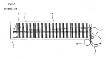
- Fig. 12 shows a media cassette and a structure for drawing media out of the media cassette, which are employed in a related art automatic media dispenser.
- a media cassette 1 is installed in the automatic media dispenser.
- the media cassette 1 may be either integrated with, or separately formed from, the automatic media dispenser.
- Media m are arranged in a stack in the media cassette 1.
- the media m are pushed toward a discharge port by a push plate 3, so that they are located in tight contact with each other.
- the push plate 3 is supported by a spring 5 so as to push the media.
- the spring 5 provides an elastic force which enables the push plate 3 to push the media.
- the pickup roller 7 is located at one end of the media cassette 1, comes into contact with and separates each sheet of the media in the media cassette 1, and then moves the separated sheet out of the media cassette 1.
- the pickup roller 7 may be formed either integrally with the media cassette 1, or separately from the media cassette 1 in the automatic media dispenser.
- a feed roller 9 and a contra-roller 10 are disposed close to and opposed to each other, so as to promote separation of a stacked sheet of the media from another sheet and transfer the single separated sheet. That is, the media are separated and transferred one sheet at a time by the feed roller 9 and the contra-roller 10 while each sheet passes through a gap between the feed roller 9 and the contra-roller 10 rotating in the same direction.
- Each sheet of the media having passed through the gap between the feed roller 9 and the contra-roller 10, is transferred by a feed roller or a belt provided at a delivery module (not shown).
- the media m which are stacked in the media cassette 1, have various sizes. Nevertheless, the media cassette 1 cannot change the way it supports or guides the media m based on the media's size and thus cannot be used for media m of various sizes. Therefore, different media cassettes 1 must be provided to accommodate respective sizes of the media m. Having many different sized media cassettes 1 to accommodate different sizes of media is expensive to the manufacturer in design costs and inventory space, and expensive to the media dispenser purchaser since several different media cassettes may need to be purchased.
- JP-A-09-315596 relates to an envelope cassette for a printer.
- a storage part for storing large quantity of envelopes is provided.
- the cassette comprises a plate motor that moves up a first paper plate onto which the envelopes are arranged until a top lever comes in contact with an envelope and a paper sensor stops the plate motor.
- US-A-4 704 061 relates to a container for use in loading notes into a currency cassette.
- the cassette comprises side plates and a base plate that can be repositioned by means of replaceable spacer members.
- An object of the present invention is to provide a media support apparatus adapted to support and guide media, which are used in an automatic media dispenser.
- a media support apparatus for a media cassette of an automatic media dispenser comprising: a base plate having a guide piece which is provided with a guide slot; a link mechanism having at least one connection pin, which is moved along the guide slot, and a connection link plate, the level of which can be adjusted; at least two media seats which are horizontally seated on the connection link plate of the connection mechanism with a predetermined spacing and are elongated along a direction; and a support mechanism for retaining the link mechanism at a predetermined level.
- a pair of guide pieces is formed on each of the opposite ends of the link mechanism.
- the link mechanism includes: a connection link plate having an upper surface on which the media seat is seated; an elevating leg rotatably connected to each of the opposite ends of the connection link plate via a connection pin; and a connection lever connected to each end of both of the elevating legs via a connection pin, which is positioned in the guide slot.
- the support mechanism includes: a support table which is movably positioned on the base plate and has a slant portion with a predetermined slant; a connection support shaft which penetrates the connection link in a traverse direction and is supported on the slant portion to retain the link mechanism; and a resilient member which provides a resilient force so that the connection support shaft is forced against the slant portion.
- the support table is positioned between the link mechanisms.
- the slant portion of the support table has a number of seating recesses formed parallel to a direction along which the connection support shaft extends, in order to seat the connection support shaft therein.
- the link mechanism is positioned on each of the opposite ends of the support table and the connection support shaft is connected to the elevating leg of the opposite link mechanisms at the same time.
- the support table has a pair of long movement apertures, through which coupling screws are coupled on the base plate, in order to position the support table.
- the media seat is adapted to move in a direction that traverses the connection link plate, the connection link plate has a serration formed along a direction that traverses the media seat, and the media seat is provided with a holder having a deformable elastic manipulation piece, which is provided with a coupling serration that can be selectively coupled with the serration.
- the media seat is provided with guides in locations corresponding to those of leading and tailing ends of the connection link plate, so that the media seat is guided to move in a direction that traverses the connection link plate.
- the link mechanism includes: a connection link plate having an upper surface on which the media seat is seated; an elevating leg rotatably connected to the connection link plate via a connection pin; and a connection pin which is positioned on an end of the elevating leg and the opposite ends of which are positioned in the guide slot.
- the support mechanism includes: a support table which is movably positioned on the base plate and has a slant portion with a predetermined slant; a support end which is integrated to the base plate and has a number of hook steps, which have different levels; a connection support shaft which penetrates the connection link in a traverse direction and is supported on the slant portion to retain the link mechanism; and a resilient member which provides a resilient force so that the connection support shaft is forced against the slant portion.
- the support table is positioned on each of the opposite ends of the link mechanism.
- the slant portion of the support table has a number of seating recesses formed parallel to a direction along which the connection support shaft extends, in order to seat the connection support shaft therein.
- connection support shaft is connected to each elevating leg of both of the link mechanisms at the same time and the opposite ends of the connection support shaft are supported on the support table.
- the support table has a pair of long movement apertures, through which coupling screws are coupled on the base plate, in order to position the support table.
- the media seat is adapted to move in a direction that traverses the connection link plate, the connection link plate has a serration which has a sectional shape of a right triangle and is formed along a direction that traverses the media seat, and the media seat is provided with a holder having a deformable elastic manipulation piece, which is provided with a coupling serration that can be selectively coupled with the serration and has a sectional shape of a right triangle.
- the present invention configured as above, is advantageous in that a single media cassette can be used for media of various sizes and it is possible to adjust the height of a feature that supports the ends of the stacked media.
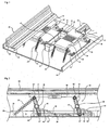
- Fig. 1 is a perspective view showing the configuration of one embodiment of a media support apparatus for a media cassette according to the present invention
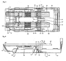
- Fig. 2 is a side view, partially broken, showing the configuration of one embodiment of a media support apparatus for a media cassette according to the present invention
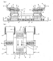
- Fig. 3 is a front view showing the configuration of an embodiment of the present invention.
- Fig. 4 is a top view showing features of an embodiment of the present invention.
- Fig. 5 is a front sectional view showing a feature for positioning a media seat, which constitutes an embodiment of the present invention
- Fig. 6 is a partial perspective view showing the configuration of a media seat, from below, which constitutes an embodiment of the present invention
- Fig. 7a shows the level adjustment feature of a media seat, during service, of an embodiment of the present invention
- Fig. 7b shows the lateral movement adjustment feature of a media seat, during service, of an embodiment of the present invention
- Fig. 7c shows the movement of a supporting table for the purpose of setting the level of a link mechanism, during service, of an embodiment of the present invention
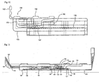
- Fig. 8 is a top view showing the configuration of another embodiment of the present invention.
- Fig. 9 is a lateral view showing the configuration of another embodiment of the present invention.
- Fig. 10 is a lateral view showing features of another embodiment of the present invention.
- Fig. 11 shows the operation of the embodiment shown in Fig. 8 ;
- Fig. 12 is a sectional view showing a media cassette, which is used in a related art automatic media dispenser, and a feature for separating the media from the cassette.
- Fig. 1 is a perspective view showing the configuration of a preferred embodiment of a media support apparatus for a media cassette according to the present invention
- Fig. 2 is a side view showing one embodiment of a media support apparatus for a media cassette according to the present invention
- Fig. 3 is a front view showing the embodiment of the present invention
- Fig. 4 is a top view showing features of the embodiment of the present invention.
- a base plate 20 is provided with guide pieces 22.
- the base plate 20 may be integrally form with the body of the media cassette or may be a separate plate which is fastened within the body of the media cassette.
- the present embodiment includes four pairs of guide pieces 22 (i.e., a total of eight).
- the guide pieces 22 protrude from the base plate 20.
- the guide pieces 22 are provided with elongated guide slots 23.
- the base plate 20 is also provided with holding pieces 25.
- the holding pieces 25 also protrude from a side of the base plate 20. Ends of resilient members 39, which will be described below, are hooked on the holding pieces 25.
- a pair of link mechanisms 30 is positioned on the left and right sides of the base plate 20 with a predetermined spacing to adjust the level at which the media are supported.
- the link mechanisms 30 are provided with elevating legs 31.
- the elevating legs 31 are rectangular plates and have a width which is slightly smaller than the spacing between the pair of guide pieces 22.
- Connection pins 31' extend through the lower ends of the elevating legs 31 and also through the guide slots 23 of the guide pieces 22.
- two elevating legs 31 are assigned to each of media seats 50, which will be described below (i.e., a total of four).
- connection pins 31' are connected with connection levers 34 from outside of the guide pieces 22.
- Each of the connection levers 34 is connected with two elevating legs 31 and one connection pin 31', which belong to a media seat 50, to interlock and drive the elevating legs 31.
- a total of four connection levers 34 may be positioned on the opposite ends of the elevating legs 31 for the operational stability of the link mechanisms 30.
- connection link plates 35 which are connected on their upper ends by connection pins 35'.
- the connection link plates 35 are of a rectangular shape having a predetermined area, as shown in Fig. 4 .
- Each of the connection link plates 35 connects two elevating legs 31 with each other.
- connection link plates 35 are provided with serrations 36 on their upper surfaces, as shown in FIGs. 3 and 4 .
- Each of the serrations 36 traverses the upper surface of each connection link plate 35, on which it is formed, and extends toward the other connection link plate 35 until it reaches the end of the connection link plate 35.
- Connection support shafts 38 extend through approximately middle portions of the elevating legs 31 in a traverse direction.
- the connection support shafts 38 connect corresponding elevating legs 31 of the pair of link mechanisms 30, which are positioned with a predetermined spacing. Accordingly, two connection support shafts 38 are used to level the connection link plates 35 which are provided on both of the link mechanisms 30.
- a resilient member 39 connects one end of one of the connection pins 35' with one of the holding pieces 25.
- Another resilient member 39 connects the other end of the connection pin 35' with another holding piece 25.
- the resilient members 39 provide a resilient force so that the connection support shafts 38 are forced into seating recesses 43 of a support table 40 (described below) and seated therein.
- the connection pin 35' which is positioned on the lefthand side of the connection link plate 35 in Fig. 2
- the other connection pin 35' which is positioned on the right-hand side in Fig. 2
- Support tables 40 are positioned on the base plate 20 between the link mechanisms 30.
- the support tables 40 retain the link mechanisms 30, more particularly the connection link plates 35, so that they are positioned at a specific level.
- the support tables 40 have slant portions 42.
- the slant portions 42 are positioned in locations corresponding to those of the connection support shafts 38 to support them.
- the slant portions 42 have a number of seating recesses 43 formed along the longitudinal direction of the connection support shafts 38 to support them more securely. As the connection support shafts 38 can be positioned in any of the seating recesses 43, they can be supported at different levels.
- the support table 40 has a plurality of movement apertures 45 formed along its longitudinal direction and parallel to one another, through which coupling screws 47 are coupled on the base plate 20. Accordingly, the range of levels at which the connection support shafts 38 may be positioned and supported by the support table 40, depends on the location of the coupling screws 47 within the movement apertures 45.
- connection link plates 35 is provided with a media seat or guide 50 on its upper surface.
- the media seats 50 can be moved along a direction which is perpendicular to the longitudinal direction of the connection link plates 35, and extend along the longitudinal direction of the media cassette.
- the media seats 50 are much longer than the connection link plates 35 and the length of the media seats 50 determines the number of media that can be stacked in the media cassette.
- the media seats 50 are supported on the upper surfaces of the connection link plates 35, as shown in FIG, 3 and the media are stacked with side edges resting on the upper surfaces of the media seats 50 in an upright position.
- the media seats 50 have side walls 53, which extend along their longitudinal sides and are perpendicular to their bottom surfaces 52. The side walls 53 are opposite to each other and guide the corresponding opposite ends of the upright media.
- the media seats 50 have holders 55 in locations corresponding to those of the serrations 36 of the connection link plates 35.
- the holders 55 are fastened on the bottom surfaces of the media seats 50, as shown in FIGs. 5 and 6 .
- Each of the holders 55 is made of molded material and has a long manipulation piece 56 on its end.
- the manipulation pieces 56 can undergo elastic deformation due to their shape and material.
- the manipulation pieces 56 have leading ends which extend toward each other, in other words, toward each side of the media seats 50.
- the manipulation pieces 56 have coupling serrations 57 formed on their surfaces, which correspond to the serrations 36 on the upper surfaces of the connection link plates 35.
- the coupling serrations 57 are coupled with the serrations 36 to prevent the media seats 50 from moving in a direction which is perpendicular to their longitudinal direction.
- the media seats 50 are provided with guides 60 which guide them to move in a direction which is perpendicular to the connection link plates 35.
- the guides 60 are positioned on the lower surfaces of the media seats 50 in locations corresponding to the leading and trailing ends of the connection link plates 35.
- the present invention seeks to support media of various sizes using a single media cassette. Accordingly, the media seats 50 are adapted to change their positions according to the horizontal (e.g. width) and vertical (e.g. height) sizes of the media.
- the level or height of the media seats 50 is adjusted by the link mechanisms 30 interacting with the support tables 40. This adjustment is based on the vertical size or height of the media to be dispensed.
- the spacing between the media seats 50 is adjusted as the media seats 50 are moved on the connection link plates 35 along a direction perpendicular to their longitudinal direction. This adjustment is based on the horizontal size of width of the media to be dispensed.
- Fig. 2 shows a state wherein the media seats 50 are positioned relatively high.
- the connection support shafts 38 are seated in seating recesses 43, which have relatively higher positions, than the other seating recesses 43 of the slant portions 42 of the support table 40 and the level of the connection link plates 35 of the link mechanisms 30 is determined accordingly.
- the resilient members 39 force and hold the connection support shafts 38 into the selected seating recesses 43 to prevent the link mechanisms 30 from moving arbitrarily.
- Modification of the level of the media seats 50 can be performed by adjusting the link mechanisms 30. Specifically, the connection pins 31' are moved from forward ends of the guide slots 23 of the guide pieces 22 to rearward ends, in other words, from a state shown in Fig. 2 to that shown in Fig. 7a .
- connection levers 34 accompany them and the lower ends of the elevating legs 31 are transferred to the other ends of the guide slots 23 together with the connection pins 31'.
- the upper ends of the elevating legs 31 are then lowered, and so are the connection link plates 35, which are connected to the upper ends of the elevating legs 31. This also lowers the media seats 50 automatically, which are positioned on the connection link plates 35.
- the connection support shafts 38 are seated in relatively lower positions from among the seating recesses 43 of the slant portions 42.
- both of the connection link plates 35 are leveled with each other, and so are both of the media seats 50.
- the media seats 50 maintain their level and are not moved by the resilient members 39, as the connection support shafts 38 are supported by the seating recesses 43 of the slant portions 42 of the support table 40.
- the spacing between the two media seats 50 is adjusted as follows: as shown in Fig. 7b , the manipulation pieces 56 of the holders 55 are lifted so that the coupling serrations 57 of the manipulation pieces 56 are separated from the serrations 36 of the connection link plates 35.
- the media seats 50 can be guided and moved freely by the guides 60. In this state, the two media seats 50 can be positioned so that they are spaced from each other as desired.
- the manipulation pieces 56 are released and naturally, resiliently returned to their original open status. After the manipulation pieces 56 resiliently open, the coupling serrations 57 are coupled with the serrations 36 to prevent the media seats 50 from moving.
- FIGS. 8 to 10 show another embodiment of the present invention.
- components the same as in the previous embodiment are given the same respective reference numerals, greater by a value of 100, and repeated description thereof will be omitted.
- a base plate 120 is provided with guide pieces 122.
- the present embodiment includes two pairs of guide pieces 122 (i.e., a total of four).
- the guide pieces 122 protrude from the base plate 120.
- the guide pieces 122 are provided with guide slots 123, which traverse them and extend along the longitudinal direction thereof.
- the base plate 120 is also provided with holding pieces 125.
- the holding pieces 125 also protrude from a side of the base plate 120. Ends of resilient members 139, which will be described below, are hooked on the holding pieces 125.
- the number of the holding pieces 125 corresponds to that of the resilient members 139.
- the present embodiment includes a total of eight holding pieces 125.
- a pair of link mechanisms 130 is positioned on the left and right sides of the base plate 120 with a predetermined spacing to adjust the level at which the media are supported.
- the link mechanisms 130 are provided with elevating legs 131.
- the elevating legs 131 are rectangular plates and have a width which is slightly smaller than the spacing between the pair of guide pieces 122.
- Connection pins 131' extends through the lower ends of the elevating legs 131 and also through the guide slots 123 of the guide pieces 122.
- one elevating leg 131 is assigned to each media seat 150, which will be described below (i.e., a total of two).
- connection link plates 135 are of a rectangular shape having a predetermined area and are positioned horizontally or parallel relative to the base plate 120. To this end, the connection link plates 135 have hook ends 137 extending from their ends along their longitudinal direction.
- the hook ends 137 may be integrated to the connection link plates 135 or may be coupled to them as separate components.
- the hook ends 137 are preferably made of metal for enhanced strength when, for example, the connection link plates 135 are expected to be subject to a large load. Sides of the hook ends 137 are selectively hooked on hook steps 145 of support ends 140', which will be described below.
- connection link plates 135 are provided with serrations 136 on their upper surfaces.
- Each of the serrations 136 traverses the upper surface of the corresponding connection link plate 135 on which it is formed, and extends toward the other connection link plate 135 until it reaches the end of its own corresponding connection link plate 135.
- the serrations 136 have a sectional shape of a right triangle, however other shapes are possible.
- connection support shaft 138 extend through portions in the approximate middle of the elevating legs 131 in a traverse direction.
- the connection support shaft 138 connects corresponding elevating legs 131 of the pair of link mechanisms 130, which are positioned with a predetermined spacing.
- the connection support shaft 138 is used to level the connection link plates 135, which are provided on both of the link mechanisms 130.
- Resilient members 139 are provided. One end of a resilient member is hooked to one of the connection pins 135' and the other end is hooked to one of the holding pieces 125.
- a total of four resilient members 139 are provided per one connection link plate 135.
- the resilient members 139 are connected closer to the opposite ends of the connection link plates 135 with a predetermined spacing, respectively.
- two of the four resilient members 139 have their ends connected to the opposite ends of the connection pins 135', respectively, and the other two of resilient members 139 have ends connected closer to the hook ends 137, respectively.
- the resilient members 139 provide a resilient force so that the connection support shafts 138 are forced against seating recesses 143 of a ramp or support table 140 (explained below), as well as against hook steps 145 of support ends 140', and are seated therein.
- Support tables 140 are positioned on the base plate 120 outside of the link mechanisms 130.
- the support tables 140 retain the link mechanisms 130, more particularly the connection link plates 135, so that they are positioned at a specific level.
- the support tables 140 have slant portions 142.
- the slant portions 142 are positioned in locations corresponding to the locations of the connection support shafts 138 to support them.
- the slant portions 142 have a number of seating recesses 143 formed along the longitudinal direction of the connection support shafts 138 to support them more securely. As the connection support shafts 138 can be positioned in any of the seating recesses 143, they can be supported at different heights.
- the support table 140 can change its position, as in the previous embodiment In other words, the support table 140 can be moved on the base plate 120 along the transfer direction of media and fixed to the base plate 120 at the desired position.
- a support end 140' is provided at one end of the base plate 120 and replaces the second support table 140 (illustrated in the previous embodiment).
- the support end 140' is integrated on a side of the base plate 120 and is positioned at a level higher than that of the support table 140.
- the support end 140' directly supports the hook end 137, which has no elevating leg 131.
- the support end 140' is formed along an inner wall of an end of the media cassette.
- the support end 140' has hook steps 145, on which the hook ends 137 are actually hooked.
- the number of the hook ends 145 may correspond to the number of the seating recesses 143 of the support table 140.
- connection link plates 135 is provided with a media seat 150 on its upper surface.
- the media seats 150 can be moved along a direction, which is perpendicular to the longitudinal direction of the connection link plates 135, and extend along the longitudinal direction of the media cassette.
- the media seats 150 are much longer than the connection link plates 135, and the length of the media seats 150 determines the number of media that can be stacked in the media cassette.
- the media seats 150 are supported on the upper surfaces of the connection link plates 135 and side edges of the media are seated on the upper surfaces of the media seats 150 such that the media rest in an upright position.
- the media seats 150 have side walls 153, which extend along their longitudinal sides and are perpendicular to their bottom surfaces 152. The side walls 153 are opposite to each other and guide the respective ends of the upright stacked media.
- the media seats 150 In order to selectively move the media seats 150 along their traverse direction on the connection link plates 135, the media seats 150 have holders 155 in locations corresponding to the serrations 136 of the connection link plates 135.
- the holders 155 are fastened on the bottom surfaces of the media seats 150.
- Each of the holders 155 is made of molded material and has a long manipulation piece 156 on its end.
- the manipulation pieces 156 can undergo elastic deformation due to their shape and material.
- the manipulation pieces 156 have leading ends which extend toward each other, in other words, toward each respective side of the media seats 150.
- the manipulation pieces 156 have coupling serrations 157 formed on their surfaces, which correspond to the serrations 136 on the upper surfaces of the connection link plates 135.
- the coupling serrations 157 are coupled with the serrations 136 to prevent the media seats 150 from moving in a direction which is perpendicular to their longitudinal direction.
- the coupling serrations 157 have a sectional shape of a right triangle. The right-angled surfaces of them face the serrations 136.
- the media seats 150 are preferably provided with guides (not shown), which guide them to move perpendicularly to the connection link plates 135, as in the previous embodiment.
- the height of the media seats 150 is adjusted as follows: the media seats 150 have their connection support shafts 138 and hook ends 137 supported on the support table 140 and the support end 140', respectively.
- the seating recesses 143 and the hook steps 145, on which the connection support shafts 138 and the hook ends 137 are seated, respectively, are simply changed.
- the connection support shafts 138 are moved away from the slant portions 142 of the support table 140, i.e. out of the seating recesses 143.
- connection support shafts 138 The movement of the connection support shafts 138 is accompanied by movement of the elevating legs 131. As a result, the connection pins 131' of the elevating legs 131 change their locations in the guide slots 123. The hook ends 137 should also be supported on different hook steps 145 to orient the media support table 150 horizontally.
- the resilient members 139 can provide a resilient force so that the connection support shafts 138 and the hook ends 137 are continuously biased to be seated in the seating recesses 143 and the hook steps 145, respectively.
- the media support table 150 does not change its height due to slight external forces, such as bumping or jarring of the media cassette. Rather, it takes a purposeful manual manipulation on the part of the user to change the height of the support table.
- a single media cassette can be used for media of various sizes, it is possible to provide a highly compatible and adaptable media cassette.
- two link mechanisms are interlocked to adjust the height of media seats based on the media's size. Therefore, the two media seats can be automatically and simultaneously leveled accurately and the media can be supported correctly.
- the media seats can be adjusted based not only on the height of the media to be dispensed, but also on the basis of the width of the media to be dispensed.
Landscapes
- Physics & Mathematics (AREA)
- General Physics & Mathematics (AREA)
- Engineering & Computer Science (AREA)
- Mechanical Engineering (AREA)
- Business, Economics & Management (AREA)
- Accounting & Taxation (AREA)
- Finance (AREA)
- Sheets, Magazines, And Separation Thereof (AREA)
- Lining Or Joining Of Plastics Or The Like (AREA)
- Unwinding Webs (AREA)
Claims (22)
- Cassette de média pour un distributeur de média automatique, comprenant :une assise de média (50, 150) pour supporter les bords inférieurs du média alignés dans une pile dans ladite cassette de média ; etun dispositif d'ajustement pour permettre à un utilisateur de sélectionner et de fixer une hauteur de ladite assise de média depuis une partie inférieure de ladite cassette de média, de façon à accueillir une taille de média ayant une dimension donnée depuis son bord inférieur jusqu'à son bord supérieur,caractérisée en ce que ledit dispositif d'ajustement comprend :une plaque de base (20, 120) formant ladite partie inférieure de ladite cassette de média, ladite plaque de base comportant un élément de guidage (22, 122) doté d'une fente de guidage (23, 123) ;un mécanisme de liaison (30, 130) comportant un axe de raccordement (31', 131') se déplaçant le long de ladite fente de guidage (23, 123), et une plaque de liaison de raccordement (35, 135), dont la hauteur peut être ajustée par un utilisateur par rapport à ladite plaque de base ; etun mécanisme de support pour retenir ledit mécanisme de liaison (30, 130), de telle sorte que ladite plaque de liaison de raccordement reste à une hauteur ajustée par l'utilisateur par rapport à ladite plaque de base.
- Cassette de média selon la revendication 1, dans laquelle ladite plaque de base (20, 120) comprend deux éléments de guidage (22, 122) dotés de fentes de guidage (23, 123) respectives, lesdits éléments de guidage (22, 122) étant fixés à ladite plaque de base (20, 120) sur les côtés opposés dudit mécanisme de liaison (30, 130), et dans lequel ledit axe de raccordement (31', 131') se déplace le long desdites fentes de guidage desdits deux éléments de guidage.
- Cassette de média selon la revendication 2, dans laquelle ledit mécanisme de liaison (30, 130) comprend également :un pied élévateur (31, 131) relié de manière rotative à ladite plaque de liaison de raccordement (35, 135) près d'une extrémité dudit pied élévateur (31, 131), et relié de manière rotative audit axe de raccordement (31', 131') près d'une autre extrémité dudit pied élévateur.
- Cassette de média selon la revendication 3, dans laquelle ledit mécanisme de support comprend :un élément flexible (39, 139) relié à ladite plaque de base (20, 120), dans lequel ledit élément flexible (39, 139) applique une force de poussée tendant à déplacer ladite une extrémité dudit pied élévateur (31, 131) vers ladite plaque de base.
- Cassette de média selon l'une quelconque des revendications 1 à 4, dans laquelle une surface supérieure de ladite plaque de liaison de raccordement (35, 135) forme ladite assise de média.
- Cassette de média selon l'une quelconque des revendications 1 à 5, dans laquelle ladite assise de média est fixée à ladite plaque de liaison de raccordement (35, 135).
- Cassette de média selon la revendication 1, dans laquelle ladite assise de média (150) comprend une première surface (153) supportant les bords latéraux du média à une extrémité du média et une seconde surface (153) supportant les bords latéraux du média à une extrémité opposée du média, et dans laquelle ledit dispositif d'ajustement comprend :une plaque de base (120) formant ladite partie inférieure de ladite cassette de média, ladite plaque de base comportant un premier élément de guidage (122) doté d'une première fente de guidage (123), un second élément de guidage (122) doté d'une seconde fente de guidage (123), un troisième élément de guidage (122) doté d'une troisième fente de guidage (123), et d'un quatrième élément de guidage (122) doté d'une quatrième fente de guidage (123) ;un premier mécanisme de liaison (130) positionné entre lesdits premier et second éléments de guidage (122), ledit premier mécanisme de liaison comportant un premier pied élévateur (131) relié de manière rotative à une première plaque de liaison de raccordement (135) près d'une première extrémité dudit premier pied élévateur, et relié de manière rotative à un premier axe de raccordement (131') près d'une seconde extrémité dudit premier pied élévateur, dans lequel ledit premier axe de raccordement est déplacé le long desdites première et seconde fentes de guidage (123), et une hauteur de ladite première plaque de liaison de raccordement peut être ajustée par l'utilisateur par rapport à ladite plaque de base ;un second mécanisme de liaison (130) positionné entre lesdits troisième et quatrième éléments de guidage (122), ledit second mécanisme de liaison comportant un second pied élévateur (131) relié de manière rotative à une seconde plaque de liaison de raccordement (135) près d'une première extrémité dudit second pied élévateur, etrelié de manière rotative à un second axe de raccordement (131') près d'une seconde extrémité dudit second pied élévateur, dans lequel ledit second axe de raccordement est déplacé le long desdites troisième et quatrième fentes de guidage, et une hauteur de ladite seconde plaque de liaison de raccordement peut être ajustée par l'utilisateur par rapport à ladite plaque de base ; etun mécanisme de support pour retenir lesdits premier et second mécanismes de liaison, de telle sorte que lesdites première et seconde plaques de liaison de raccordement restent à une hauteur ajustée par l'utilisateur par rapport à ladite plaque de base.
- Cassette de média selon la revendication 7, dans laquelle ledit mécanisme de support comprend :une table de support (140) positionnée sur ladite plaque de base entre lesdits premier et second mécanismes de liaison, ladite table de support ayant une surface inclinée (142) ; etun axe de support de raccordement (138) relié auxdits premier et second pieds élévateurs et s'accouplant avec ladite surface inclinée de ladite table de support.
- Cassette de média selon la revendication 8, dans laquelle ledit mécanisme de support comprend également :des éléments flexibles (139) reliés à ladite plaque de base, dans lesquels lesdits éléments flexibles appliquent une force de poussée tendant à déplacer lesdites premières extrémités desdits premier et second pieds élévateurs vers ladite plaque de base de telle sorte que ledit axe de support de raccordement (138) repose contre ladite surface inclinée (142) de ladite table de support (140).
- Cassette de média selon la revendication 8, dans laquelle ladite surface inclinée (142) de ladite table de support comporte plusieurs encastrements d'assise (143) formés parallèlement à une direction le long de laquelle ledit axe de support de raccordement s'étend, afin de supporter ledit axe de support de raccordement dans ceux-ci.
- Cassette de média selon la revendication 8, dans laquelle ladite table de support (140) comporte au moins une ouverture en fente (145), à travers laquelle au moins une vis d'accouplement (147) passe pour raccorder ladite table de support à ladite plaque de base, de telle sorte que ladite table de support puisse être fixée à ladite plaque de base dans une position ajustable par l'utilisateur.
- Cassette de média selon la revendication 8, dans laquelle ledit mécanisme de support comprend également :une extrémité de support (140') reliée à, ou intégrée avec, ladite plaque de base et comportant plusieurs épaulements d'accrochage (145), à des hauteurs différentes depuis ladite plaque de base ; etau moins un crochet (137) formé sur une extrémité de ladite première plaque de liaison de raccordement et de ladite seconde plaque de liaison de raccordement, respectivement, dans lequel ledit au moins un crochet de chacune desdites première et seconde plaques de liaison de raccordement peut être accouplé sélectivement à l'un des épaulements d'accrochage de l'extrémité de support.
- Cassette de média selon la revendication 12, dans laquelle ladite extrémité de support est formée près d'un bord de ladite plaque de base et est formée comme une rampe comportant une surface inclinée s'étendant loin de ladite plaque de base.
- Cassette de média selon la revendication 1, dans laquelle ledit mécanisme d'ajustement comprend :une plaque de base (20) formant ladite partie inférieure de ladite cassette de média, ladite plaque de base comportant un premier élément de guidage doté d'une première fente de guidage , un second élément de guidage doté d'une seconde fente de guidage, un troisième élément de guidage doté d'une troisième fente de guidage, et un quatrième élément de guidage doté d'une quatrième fente de guidage ;un premier mécanisme de liaison (30) positionné entre lesdits premier et second éléments de guidage, ledit premier mécanisme de liaison comportant un premier pied élévateur relié de manière rotative à une première plaque de liaison de raccordement près d'une première extrémité dudit premier pied élévateur, et relié de manière rotative à un premier axe de raccordement près d'une seconde extrémité dudit premier pied élévateur, dans lequel ledit premier axe de raccordement est déplacé le long desdites première et seconde fentes de guidage ;un second mécanisme de liaison (30) positionné entre lesdits troisième et quatrième éléments de guidage, ledit second mécanisme de liaison comportant un second pied élévateur relié de manière rotative à une première plaque de liaison de raccordement près d'une première extrémité dudit second pied élévateur, et relié de manière rotative à un second axe de raccordement près d'une seconde extrémité dudit second pied élévateur, dans lequel ledit second axe de raccordement est déplacé le long desdites troisième et quatrième fentes de guidage, et une hauteur de ladite première plaque de liaison de raccordement peut être ajustée par l'utilisateur par rapport à ladite plaque de base ; etun premier levier de raccordement (34) reliant ledit premier axe de raccordement audit second axe de raccordement.
- Cassette de média selon la revendication 14, dans laquelle ladite assise de média comprend une première surface supportant les bords latéraux du média à une extrémité du média et une seconde surface supportant les bords latéraux du média à une extrémité opposée du média, et dans laquelle ledit dispositif d'ajustement comprend également :ladite plaque de base (20) comportant un cinquième élément de guidage doté d'une cinquième fente de guidage, un sixième élément de guidage doté d'une sixième fente de guidage, un septième élément de guidage doté d'une septième fente de guidage, et un huitième élément de guidage doté d'une huitième fente de guidage ;un troisième mécanisme de liaison (30) positionné entre lesdits cinquième et sixième éléments de guidage, ledit troisième mécanisme de liaison comportant un troisième pied élévateur relié de manière rotative à une seconde plaque de liaison de raccordement près d'une première extrémité dudit troisième pied élévateur, et relié de manière rotative à un troisième axe de raccordement près d'une seconde extrémité dudit troisième pied élévateur, dans lequel ledit troisième axe de raccordement est déplacé le long desdites cinquième et sixième fentes de guidage ;un quatrième mécanisme de liaison (30) positionné entre lesdits septième et huitième éléments de guidage, ledit quatrième mécanisme de liaison comportant un quatrième pied élévateur relié de manière rotative à ladite seconde plaque de liaison de raccordement près d'une première extrémité dudit quatrième pied élévateur, et relié de manière rotative à un quatrième axe de raccordement près d'une seconde extrémité dudit quatrième pied élévateur, dans lequel ledit quatrième axe de raccordement est déplacé le long desdites septième et huitième fentes de guidage, et une hauteur de ladite seconde plaque de liaison de raccordement peut être ajustée par l'utilisateur par rapport à ladite plaque de base ;un second levier de raccordement (34) reliant ledit troisième axe de raccordement audit quatrième axe de raccordement ; etun mécanisme de support pour retenir lesdits premier, second, troisième et quatrième mécanismes de liaison, de telle sorte que lesdites première et seconde plaques de raccordement restent à une hauteur ajustée par l'utilisateur par rapport à ladite plaque de base.
- Cassette de média selon la revendication 15, dans laquelle ledit mécanisme de support comprend :une première table de support (40) positionnée sur ladite plaque de base entre lesdits premier et second mécanismes de liaison, ladite première table de support ayant une surface inclinée ;un premier axe de support de raccordement (38) relié auxdits premier et second pieds élévateurs, et s'accouplant avec ladite surface inclinée de ladite première table de support ;une seconde table de support (40) positionnée sur ladite plaque de base entre lesdits troisième et quatrième mécanismes de liaison, ladite seconde table de support ayant une surface inclinée ; etun second axe de support de raccordement (38) relié auxdits troisième et quatrième pieds élévateurs, et s'accouplant avec ladite surface inclinée de ladite seconde table de support.
- Cassette de média selon la revendication 16, dans laquelle ledit mécanisme de support comprend également :des éléments flexibles (39) reliés à ladite plaque de base, dans lesquels lesdits éléments flexibles appliquent une force de poussée tendant à déplacer lesdites premières extrémités desdits premier, second, troisième et quatrième pieds élévateurs vers ladite plaque de base de telle sorte que lesdits premier et second axes de support de raccordement reposent contre lesdites surfaces inclinées desdites première et seconde tables de support, respectivement.
- Cassette de média selon la revendication 17, dans laquelle lesdites première et seconde tables de support (40) sont reliées ensemble et comportent au moins une ouverture en fente (45) à travers laquelle au moins une vis d'accouplement (47) passe pour raccorder lesdites première et seconde table de support à ladite plaque de base, de telle sorte que lesdites première et seconde tables de support puissent être fixées à ladite plaque de base dans une position ajustable par l'utilisateur.
- Cassette de média selon la revendication 1, dans laquelle ladite assise de média (50, 150) comprend une première surface supportant les bords latéraux du média à une extrémité du média et une seconde surface supportant les bords latéraux du média à une extrémité opposée du média ; et comprenant également
un second dispositif d'ajustement pour permettre à un utilisateur de déplacer au moins l'une desdites première et seconde surfaces par rapport à l'autre desdites première et seconde surfaces, de façon à accueillir des médias de différentes largeurs sur ladite assise de média de ladite cassette de média. - Cassette de média selon la revendication 19, dans laquelle ledit second dispositif d'ajustement permet à un utilisateur de déplacer à la fois lesdites première et seconde surfaces, de façon à accueillir des médias de différentes largeurs sur ladite assise de média de ladite cassette de média.
- Cassette de média selon la revendication 19, dans laquelle ladite au moins une desdites première et seconde surfaces est adaptée pour se déplacer dans une direction traversant une plaque de liaison de raccordement sous-jacente, ladite plaque de liaison de raccordement comportant une dentelure formée sur celle-ci, et ladite au moins une desdites première et seconde surfaces étant dotée d'un dispositif de maintien (55, 155) comportant un élément de manipulation élastique déformable (56, 156) comprenant une dentelure d'accouplement (57, 157) pouvant être accouplée sélectivement avec ladite dentelure sur ladite plaque de liaison de raccordement.
- Cassette de média selon la revendication 21, dans laquelle ladite au moins une desdites première et seconde surfaces est dotée de guides dans des emplacements correspondant à un bord d'attaque et un bord de fuite de ladite plaque de liaison de raccordement sous jacente, de telle sorte que ladite au moins une desdites première et seconde surfaces soit guidée pour se déplacer dans une direction traversant ladite plaque de liaison de raccordement sous-jacente.
Applications Claiming Priority (2)
| Application Number | Priority Date | Filing Date | Title |
|---|---|---|---|
| KR2003101536 | 2003-12-31 | ||
| KR10-2003-0101536A KR100527159B1 (ko) | 2003-12-31 | 2003-12-31 | 매체자동지급기의 매체카세트용 매체지지장치 |
Publications (3)
| Publication Number | Publication Date |
|---|---|
| EP1559670A2 EP1559670A2 (fr) | 2005-08-03 |
| EP1559670A3 EP1559670A3 (fr) | 2005-09-21 |
| EP1559670B1 true EP1559670B1 (fr) | 2010-02-10 |
Family
ID=34651506
Family Applications (1)
| Application Number | Title | Priority Date | Filing Date |
|---|---|---|---|
| EP04030968A Active EP1559670B1 (fr) | 2003-12-31 | 2004-12-29 | Cassette de média d'un distributeur de média automatique |
Country Status (5)
| Country | Link |
|---|---|
| US (1) | US7591463B2 (fr) |
| EP (1) | EP1559670B1 (fr) |
| KR (1) | KR100527159B1 (fr) |
| CN (1) | CN1313338C (fr) |
| DE (1) | DE602004025449D1 (fr) |
Families Citing this family (14)
| Publication number | Priority date | Publication date | Assignee | Title |
|---|---|---|---|---|
| CA2689840C (fr) * | 2002-12-31 | 2012-03-13 | Diebold, Incorporated | Dispositif de cassette a billets de banque pour distributeur automatique de billets |
| GB2439733B (en) * | 2006-07-06 | 2008-05-21 | Int Currency Tech | Card dispenser adjustable subject to the size of the cards to be dispensed |
| US7513432B2 (en) * | 2006-07-11 | 2009-04-07 | International Currency Technologies Corporation | Card dispenser adjustable subject to the size of the cards to be dispensed |
| DE102008016588A1 (de) * | 2008-03-31 | 2009-10-01 | Wincor Nixdorf International Gmbh | Wertscheinkassette mit einer Wertscheinführung |
| JP5043984B2 (ja) * | 2010-05-10 | 2012-10-10 | キヤノン株式会社 | プリント装置およびプリント装置の設置方法 |
| CN101894417B (zh) * | 2010-08-12 | 2012-07-25 | 恒银金融科技有限公司 | 一种atm钱箱的钞仓宽度调整装置 |
| CN101894418B (zh) * | 2010-08-12 | 2012-08-22 | 恒银金融科技有限公司 | 一种atm钱箱的钞仓高度调整装置 |
| US8899475B2 (en) * | 2010-08-26 | 2014-12-02 | Ncr Corporation | Media presenter |
| US8366107B2 (en) * | 2010-08-26 | 2013-02-05 | Ncr Corporation | Media presenter |
| CN104103125B (zh) * | 2014-08-08 | 2017-03-22 | 广州广电运通金融电子股份有限公司 | 钞箱及其纸币尺寸调节装置 |
| US9615674B2 (en) * | 2015-03-11 | 2017-04-11 | Trinity, Llc | Can dispenser and merchandiser |
| CN108349670B (zh) * | 2015-09-30 | 2019-10-29 | 惠普发展公司,有限责任合伙企业 | 介质托盘组件 |
| CN109035547B (zh) * | 2017-06-12 | 2020-10-27 | 山东新北洋信息技术股份有限公司 | 币箱及纸币处理装置 |
| CN110723569B (zh) * | 2019-10-15 | 2021-10-15 | 朱笑笑 | 一种喷墨打印机用纸张填充装置 |
Family Cites Families (7)
| Publication number | Priority date | Publication date | Assignee | Title |
|---|---|---|---|---|
| GB2182717B (en) * | 1985-11-12 | 1989-12-06 | Ncr Co | A container and method for loading currency notes into a currency cassette |
| US5163670A (en) * | 1991-03-04 | 1992-11-17 | Compaq Computer Corporation | Dual bin paper feed tray for an image reproduction machine such as a printer or copier |
| JPH09315596A (ja) * | 1996-05-31 | 1997-12-09 | Matsushita Electric Ind Co Ltd | 印字装置用の封筒カセット |
| US6287032B1 (en) * | 2000-01-05 | 2001-09-11 | Hewlett-Packard Company | Media tray supporter and method of using same |
| CN2562011Y (zh) * | 2002-08-21 | 2003-07-23 | 天津市阿斯米机械设备制造安装工程有限公司 | 物料阀 |
| JP3878098B2 (ja) * | 2002-09-17 | 2007-02-07 | 株式会社沖データ | 給紙カセット及び給紙装置 |
| JP2004292092A (ja) * | 2003-03-26 | 2004-10-21 | Brother Ind Ltd | 用紙案内装置及びそれを備えた印刷装置 |
-
2003
- 2003-12-31 KR KR10-2003-0101536A patent/KR100527159B1/ko active IP Right Grant
-
2004
- 2004-12-29 DE DE602004025449T patent/DE602004025449D1/de active Active
- 2004-12-29 EP EP04030968A patent/EP1559670B1/fr active Active
- 2004-12-29 US US11/023,469 patent/US7591463B2/en active Active
- 2004-12-31 CN CNB200410081876XA patent/CN1313338C/zh active Active
Also Published As
| Publication number | Publication date |
|---|---|
| KR100527159B1 (ko) | 2005-11-09 |
| DE602004025449D1 (de) | 2010-03-25 |
| CN1636849A (zh) | 2005-07-13 |
| US7591463B2 (en) | 2009-09-22 |
| EP1559670A2 (fr) | 2005-08-03 |
| CN1313338C (zh) | 2007-05-02 |
| US20050184444A1 (en) | 2005-08-25 |
| KR20050070930A (ko) | 2005-07-07 |
| EP1559670A3 (fr) | 2005-09-21 |
Similar Documents
| Publication | Publication Date | Title |
|---|---|---|
| EP1559670B1 (fr) | Cassette de média d'un distributeur de média automatique | |
| US7722034B2 (en) | Sheet discharge tray, as well as sheet conveying apparatus, image forming apparatus, and image reading apparatus having the sheet discharge tray | |
| EP0748754A2 (fr) | Dispositif de réception et d'empilage de feuilles | |
| US4098501A (en) | Cassette type sheet feed apparatus for copying machine or the like | |
| JP3372066B2 (ja) | ペーパー・カセット | |
| US7559547B2 (en) | Tray for non-uniform thickness objects | |
| KR20030093874A (ko) | 용지 적재크기를 가변시킬 수 있는 급지 카세트 | |
| US6893015B2 (en) | Paper tray for a printing mechanism | |
| US6629693B2 (en) | Sheet media handling system and printer having the same | |
| US7946574B2 (en) | Sheet material feeder | |
| EP0844202A2 (fr) | Plateau pour supports d'impression | |
| US20080099986A1 (en) | Media registration devices | |
| JPH05294471A (ja) | シート積載装置 | |
| US6182963B1 (en) | Automatic force balance adjustment for sheet material cassette trays | |
| JP3688050B2 (ja) | 排紙積載装置 | |
| GB2032397A (en) | Mechanism for Dispensing Flat Articles | |
| CA2361656C (fr) | Dispositif de mise a niveau traitant du papier a deux epaisseurs. | |
| US7036816B2 (en) | Paper feeding cassette for image forming apparatus | |
| EP0722839A2 (fr) | Imprimante à jet d'encre avec un bac d'entrée auxiliaire à grand volume | |
| JP4462774B2 (ja) | 給紙カセット、および給紙方法 | |
| JP3547544B2 (ja) | 給紙装置 | |
| JP2017128425A (ja) | シート給送装置、画像形成装置及びシート収納装置 | |
| JP4170746B2 (ja) | 小サイズ印刷物用アタッチメント及び排紙台 | |
| JP4115103B2 (ja) | 給紙装置 | |
| JP4009015B2 (ja) | 分離給紙装置 |
Legal Events
| Date | Code | Title | Description |
|---|---|---|---|
| PUAI | Public reference made under article 153(3) epc to a published international application that has entered the european phase |
Free format text: ORIGINAL CODE: 0009012 |
|
| 17P | Request for examination filed |
Effective date: 20050128 |
|
| AK | Designated contracting states |
Kind code of ref document: A2 Designated state(s): AT BE BG CH CY CZ DE DK EE ES FI FR GB GR HU IE IS IT LI LT LU MC NL PL PT RO SE SI SK TR |
|
| AX | Request for extension of the european patent |
Extension state: AL BA HR LV MK YU |
|
| PUAL | Search report despatched |
Free format text: ORIGINAL CODE: 0009013 |
|
| AK | Designated contracting states |
Kind code of ref document: A3 Designated state(s): AT BE BG CH CY CZ DE DK EE ES FI FR GB GR HU IE IS IT LI LT LU MC NL PL PT RO SE SI SK TR |
|
| AX | Request for extension of the european patent |
Extension state: AL BA HR LV MK YU |
|
| AKX | Designation fees paid |
Designated state(s): AT BE BG CH CY CZ DE DK EE ES FI FR GB GR HU IE IS IT LI LT LU MC NL PL PT RO SE SI SK TR |
|
| 17Q | First examination report despatched |
Effective date: 20070515 |
|
| GRAP | Despatch of communication of intention to grant a patent |
Free format text: ORIGINAL CODE: EPIDOSNIGR1 |
|
| RTI1 | Title (correction) |
Free format text: MEDIA CASSETTE FOR AN AUTOMATIC MEDIA DISPENSER |
|
| RBV | Designated contracting states (corrected) |
Designated state(s): DE FR GB NL |
|
| GRAS | Grant fee paid |
Free format text: ORIGINAL CODE: EPIDOSNIGR3 |
|
| GRAA | (expected) grant |
Free format text: ORIGINAL CODE: 0009210 |
|
| AK | Designated contracting states |
Kind code of ref document: B1 Designated state(s): DE FR GB NL |
|
| REG | Reference to a national code |
Ref country code: GB Ref legal event code: FG4D |
|
| REF | Corresponds to: |
Ref document number: 602004025449 Country of ref document: DE Date of ref document: 20100325 Kind code of ref document: P |
|
| REG | Reference to a national code |
Ref country code: NL Ref legal event code: T3 |
|
| PLBE | No opposition filed within time limit |
Free format text: ORIGINAL CODE: 0009261 |
|
| STAA | Information on the status of an ep patent application or granted ep patent |
Free format text: STATUS: NO OPPOSITION FILED WITHIN TIME LIMIT |
|
| 26N | No opposition filed |
Effective date: 20101111 |
|
| REG | Reference to a national code |
Ref country code: NL Ref legal event code: SD Effective date: 20130715 |
|
| REG | Reference to a national code |
Ref country code: FR Ref legal event code: TP Owner name: LG CNS CO., LTD., KR Effective date: 20130729 |
|
| REG | Reference to a national code |
Ref country code: GB Ref legal event code: 732E Free format text: REGISTERED BETWEEN 20130822 AND 20130828 |
|
| REG | Reference to a national code |
Ref country code: DE Ref legal event code: R082 Ref document number: 602004025449 Country of ref document: DE Representative=s name: VOSSIUS & PARTNER, DE |
|
| REG | Reference to a national code |
Ref country code: DE Ref legal event code: R082 Ref document number: 602004025449 Country of ref document: DE Representative=s name: VOSSIUS & PARTNER, DE Effective date: 20130923 Ref country code: DE Ref legal event code: R081 Ref document number: 602004025449 Country of ref document: DE Owner name: LG CNS CO., LTD., KR Free format text: FORMER OWNER: LG N-SYS. INC., SEOUL, KR Effective date: 20130923 Ref country code: DE Ref legal event code: R082 Ref document number: 602004025449 Country of ref document: DE Representative=s name: VOSSIUS & PARTNER PATENTANWAELTE RECHTSANWAELT, DE Effective date: 20130923 |
|
| REG | Reference to a national code |
Ref country code: FR Ref legal event code: PLFP Year of fee payment: 12 |
|
| REG | Reference to a national code |
Ref country code: FR Ref legal event code: PLFP Year of fee payment: 13 |
|
| REG | Reference to a national code |
Ref country code: FR Ref legal event code: PLFP Year of fee payment: 14 |
|
| REG | Reference to a national code |
Ref country code: DE Ref legal event code: R082 Ref document number: 602004025449 Country of ref document: DE Representative=s name: VOSSIUS & PARTNER PATENTANWAELTE RECHTSANWAELT, DE Ref country code: DE Ref legal event code: R081 Ref document number: 602004025449 Country of ref document: DE Owner name: ATEC AP CO., LTD., SEONGNAM-SI, KR Free format text: FORMER OWNER: LG CNS CO., LTD., SEOUL, KR |
|
| REG | Reference to a national code |
Ref country code: GB Ref legal event code: 732E Free format text: REGISTERED BETWEEN 20181220 AND 20181224 |
|
| REG | Reference to a national code |
Ref country code: NL Ref legal event code: PD Owner name: ATEC AP CO., LTD.; KR Free format text: DETAILS ASSIGNMENT: CHANGE OF OWNER(S), ASSIGNMENT; FORMER OWNER NAME: LG CNS CO., LTD. Effective date: 20191114 |
|
| PGFP | Annual fee paid to national office [announced via postgrant information from national office to epo] |
Ref country code: FR Payment date: 20201209 Year of fee payment: 17 Ref country code: GB Payment date: 20201209 Year of fee payment: 17 |
|
| PGFP | Annual fee paid to national office [announced via postgrant information from national office to epo] |
Ref country code: NL Payment date: 20201208 Year of fee payment: 17 |
|
| REG | Reference to a national code |
Ref country code: NL Ref legal event code: MM Effective date: 20220101 |
|
| GBPC | Gb: european patent ceased through non-payment of renewal fee |
Effective date: 20211229 |
|
| PG25 | Lapsed in a contracting state [announced via postgrant information from national office to epo] |
Ref country code: NL Free format text: LAPSE BECAUSE OF NON-PAYMENT OF DUE FEES Effective date: 20220101 |
|
| PG25 | Lapsed in a contracting state [announced via postgrant information from national office to epo] |
Ref country code: GB Free format text: LAPSE BECAUSE OF NON-PAYMENT OF DUE FEES Effective date: 20211229 |
|
| PG25 | Lapsed in a contracting state [announced via postgrant information from national office to epo] |
Ref country code: FR Free format text: LAPSE BECAUSE OF NON-PAYMENT OF DUE FEES Effective date: 20211231 |
|
| PGFP | Annual fee paid to national office [announced via postgrant information from national office to epo] |
Ref country code: DE Payment date: 20221205 Year of fee payment: 19 |