EP1559591A2 - Zentrale Reifendruckregelanlage für eine Antriebsachse - Google Patents
Zentrale Reifendruckregelanlage für eine Antriebsachse Download PDFInfo
- Publication number
- EP1559591A2 EP1559591A2 EP05250144A EP05250144A EP1559591A2 EP 1559591 A2 EP1559591 A2 EP 1559591A2 EP 05250144 A EP05250144 A EP 05250144A EP 05250144 A EP05250144 A EP 05250144A EP 1559591 A2 EP1559591 A2 EP 1559591A2
- Authority
- EP
- European Patent Office
- Prior art keywords
- wheel
- seal
- bore
- face
- axle
- Prior art date
- Legal status (The legal status is an assumption and is not a legal conclusion. Google has not performed a legal analysis and makes no representation as to the accuracy of the status listed.)
- Withdrawn
Links
Images


Classifications
-
- B—PERFORMING OPERATIONS; TRANSPORTING
- B60—VEHICLES IN GENERAL
- B60C—VEHICLE TYRES; TYRE INFLATION; TYRE CHANGING; CONNECTING VALVES TO INFLATABLE ELASTIC BODIES IN GENERAL; DEVICES OR ARRANGEMENTS RELATED TO TYRES
- B60C23/00—Devices for measuring, signalling, controlling, or distributing tyre pressure or temperature, specially adapted for mounting on vehicles; Arrangement of tyre inflating devices on vehicles, e.g. of pumps or of tanks; Tyre cooling arrangements
- B60C23/001—Devices for manually or automatically controlling or distributing tyre pressure whilst the vehicle is moving
- B60C23/003—Devices for manually or automatically controlling or distributing tyre pressure whilst the vehicle is moving comprising rotational joints between vehicle-mounted pressure sources and the tyres
- B60C23/00309—Devices for manually or automatically controlling or distributing tyre pressure whilst the vehicle is moving comprising rotational joints between vehicle-mounted pressure sources and the tyres characterised by the location of the components, e.g. valves, sealings, conduits or sensors
- B60C23/00336—Devices for manually or automatically controlling or distributing tyre pressure whilst the vehicle is moving comprising rotational joints between vehicle-mounted pressure sources and the tyres characterised by the location of the components, e.g. valves, sealings, conduits or sensors on the axles
-
- B—PERFORMING OPERATIONS; TRANSPORTING
- B60—VEHICLES IN GENERAL
- B60C—VEHICLE TYRES; TYRE INFLATION; TYRE CHANGING; CONNECTING VALVES TO INFLATABLE ELASTIC BODIES IN GENERAL; DEVICES OR ARRANGEMENTS RELATED TO TYRES
- B60C23/00—Devices for measuring, signalling, controlling, or distributing tyre pressure or temperature, specially adapted for mounting on vehicles; Arrangement of tyre inflating devices on vehicles, e.g. of pumps or of tanks; Tyre cooling arrangements
- B60C23/001—Devices for manually or automatically controlling or distributing tyre pressure whilst the vehicle is moving
- B60C23/003—Devices for manually or automatically controlling or distributing tyre pressure whilst the vehicle is moving comprising rotational joints between vehicle-mounted pressure sources and the tyres
- B60C23/00309—Devices for manually or automatically controlling or distributing tyre pressure whilst the vehicle is moving comprising rotational joints between vehicle-mounted pressure sources and the tyres characterised by the location of the components, e.g. valves, sealings, conduits or sensors
- B60C23/00318—Devices for manually or automatically controlling or distributing tyre pressure whilst the vehicle is moving comprising rotational joints between vehicle-mounted pressure sources and the tyres characterised by the location of the components, e.g. valves, sealings, conduits or sensors on the wheels or the hubs
-
- B—PERFORMING OPERATIONS; TRANSPORTING
- B60—VEHICLES IN GENERAL
- B60C—VEHICLE TYRES; TYRE INFLATION; TYRE CHANGING; CONNECTING VALVES TO INFLATABLE ELASTIC BODIES IN GENERAL; DEVICES OR ARRANGEMENTS RELATED TO TYRES
- B60C23/00—Devices for measuring, signalling, controlling, or distributing tyre pressure or temperature, specially adapted for mounting on vehicles; Arrangement of tyre inflating devices on vehicles, e.g. of pumps or of tanks; Tyre cooling arrangements
- B60C23/001—Devices for manually or automatically controlling or distributing tyre pressure whilst the vehicle is moving
- B60C23/003—Devices for manually or automatically controlling or distributing tyre pressure whilst the vehicle is moving comprising rotational joints between vehicle-mounted pressure sources and the tyres
- B60C23/00354—Details of valves
-
- B—PERFORMING OPERATIONS; TRANSPORTING
- B60—VEHICLES IN GENERAL
- B60C—VEHICLE TYRES; TYRE INFLATION; TYRE CHANGING; CONNECTING VALVES TO INFLATABLE ELASTIC BODIES IN GENERAL; DEVICES OR ARRANGEMENTS RELATED TO TYRES
- B60C23/00—Devices for measuring, signalling, controlling, or distributing tyre pressure or temperature, specially adapted for mounting on vehicles; Arrangement of tyre inflating devices on vehicles, e.g. of pumps or of tanks; Tyre cooling arrangements
- B60C23/001—Devices for manually or automatically controlling or distributing tyre pressure whilst the vehicle is moving
- B60C23/003—Devices for manually or automatically controlling or distributing tyre pressure whilst the vehicle is moving comprising rotational joints between vehicle-mounted pressure sources and the tyres
- B60C23/00363—Details of sealings
-
- B—PERFORMING OPERATIONS; TRANSPORTING
- B60—VEHICLES IN GENERAL
- B60C—VEHICLE TYRES; TYRE INFLATION; TYRE CHANGING; CONNECTING VALVES TO INFLATABLE ELASTIC BODIES IN GENERAL; DEVICES OR ARRANGEMENTS RELATED TO TYRES
- B60C23/00—Devices for measuring, signalling, controlling, or distributing tyre pressure or temperature, specially adapted for mounting on vehicles; Arrangement of tyre inflating devices on vehicles, e.g. of pumps or of tanks; Tyre cooling arrangements
- B60C23/001—Devices for manually or automatically controlling or distributing tyre pressure whilst the vehicle is moving
- B60C23/003—Devices for manually or automatically controlling or distributing tyre pressure whilst the vehicle is moving comprising rotational joints between vehicle-mounted pressure sources and the tyres
- B60C23/0039—Devices for manually or automatically controlling or distributing tyre pressure whilst the vehicle is moving comprising rotational joints between vehicle-mounted pressure sources and the tyres specially adapted for driven wheels
Definitions
- the subject invention relates to a central tire inflation (CTI) system that utilizes passages formed within rotating wheel shafts to provide an easily sealed flow path to conduct air from a vehicle air supply to a tire assembly on a drive axle.
- the passage in each wheel shaft includes a fluid inlet formed at an inboard shaft end that communicates with the air supply and a fluid outlet formed at an outboard shaft end that communicates with the tire assembly.
- CTI systems automatically supply air to vehicle tires when certain predetermined conditions are met. In a typical situation, the CTI system will automatically add air to a tire that becomes under-inflated during vehicle operation.
- CTI systems typically include sensors and pressure regulators for monitoring the pressure in each of the vehicle's tires. When pressure in any tire drops below a predetermined level, the system automatically supplies air to that tire until a desired tire pressure is achieved.
- CTI systems include an air tank that is mounted on the vehicle. Air is supplied from the tank to the tires by using various methods. CTI systems can be incorporated into drive or non-drive axles. Traditionally, for either type of axle, CTI systems include an air connection that allows air to be supplied from a non-rotating air source to rotating tires. Some systems include an air connection that is mounted for rotation with a wheel hub assembly at one end, and which is mounted at an opposite end to a non-rotating axle tube for a non-drive axle. In these systems, air is supplied from the tank to an interior of the axle tube. Air from inside the axle passes through the air connection and is conducted to the rotating tires.
- CTI systems for drive axles have been more difficult to incorporate into conventional wheel ends.
- these CTI systems use drilled passageways in rotating wheel hubs in combination with drilled passageways in non-rotating spindles. This configuration requires large, expensive seals, is difficult to assemble, and is expensive to machine. Further, wheel hubs for drive axles using disc brakes and single tires often do not have enough packaging space to accommodate drilled passageways. Thus, using a CTI system for such a configuration is not practical.
- CTI systems for drive axles have utilized a pair of drilled passageways formed within a rotating axle shaft.
- a radial air passage is drilled into the axle shaft to connect with a laterally extending passage.
- An air coupling surrounds the axle shaft at the radial air passage location to provide a sealed circumferential air compartment between an external surface of the rotating axle shaft and an interior surface of the air coupling. Air is transferred from the air source and into the radial passageway by way of the air compartment.
- the air coupling is a complex mechanism requiring several component pieces and multiple seals, which makes the coupling very expensive. Further, assembling the coupling onto the axle shaft is difficult and time consuming. Also, the system is difficult to maintain and repair.
- a more cost effective CTI system for a drive axle is needed.
- the system must be easily incorporated into the drive axle without requiring extensive machining, assembly, or requiring passageways formed within the rotating wheel hub. Further, the system should be easy to maintain and repair as well as overcoming the other above-mentioned deficiencies with prior art systems.
- a tire inflation system for a vehicle wheel end assembly includes a driving input member and a driven output member.
- the output member includes a wheel shaft that drives a wheel hub and tire assembly about a wheel axis of rotation.
- the wheel shaft includes a laterally extending bore that defines a fluid inlet at a first end, which is in fluid communication with a vehicle air supply, and a fluid outlet at a second end, which is in fluid communication with the tire assembly.
- An air supply component cooperates with the vehicle air supply to transfer air from a non-rotating vehicle structure to the bore that is formed in the rotating wheel shaft.
- a seal assembly is mounted for rotation with the first end of the wheel shaft to provide a sealed environment as air is transferred from the non-rotating structure to the rotating wheel shaft.
- the bore extends through the entire length of the wheel shaft from a first end face to a second end face.
- the air supply component includes a base portion that is mounted to non-rotating wheel structure and an air conduit that extends from the base portion and into the bore at the first end face.
- the fluid inlet and fluid outlets are coaxial with the laterally extending bore.
- the subject invention is incorporated into an inverted portal drive axle.
- the inverted portal drive axle includes an input driven by a vehicle power source and defining a longitudinal axis.
- the input is operably coupled to a differential, which is in driving engagement with first and second axle shafts.
- the input is positioned laterally closer to one wheel assembly than the other wheel assembly, thus, one of the first or second axle shafts is significantly longer than the other axle shaft.
- Each axle shaft drives a gear set that raises the driving input from a lower axle shaft level up to a higher wheel axis level.
- the gear sets drive the wheel shafts, which in turn drive the wheel hubs.
- the bore is coaxial with the wheel axis of rotation, which is parallel to and spaced apart from an axle shaft axis of rotation.
- the fluid inlets at the inboard ends of the wheel shafts are easily accessed through a non-rotating gearbox or axle housing.
- the air supply component can be easily installed to communicate with the wheel shaft bore without interfering with other wheel components and without requiring significant wheel modifications.
- a connector and hose assembly are operably coupled to each fluid outlet at the outboard end of the wheel shafts to conduct the air to the tire assemblies.
- the seal assembly cooperates with the first or inboard end face of the rotating wheel shaft.
- the seal assembly includes a seal body and at least one resilient seal member, which are mounted for rotation with the wheel shaft.
- the seal body is at least partially received within a secondary bore formed at the inboard end face.
- the secondary bore is preferably coaxial with the laterally extending bore and is of greater diameter than the bore.
- the resilient seal is supported and held in place by the seal body to provide a sealed air path as air flows from the air supply, through the air conduit, through the laterally extending bore, and out to the tire assemblies.
- the subject invention utilizes the wheel shaft to provide a single, easily sealed airflow passage for a tire inflation system that can be incorporated into many different types of wheel configurations.
- the system is simple to maintain because the wheel hub does not have to be removed in order to repair or replace any tire inflation system component.
- the subject invention utilizes smaller, less complex, and less expensive components.
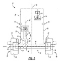
- FIG 1 shows a schematic view of a central tire inflation (CTI) system 10 incorporated into a drive axle assembly 12.
- the drive axle assembly 12 is an inverted portal drive axle, however, the CTI system 10 could be used in portal drive axles, or other similar drive axles known in the art.
- the CTI system 10 includes an air supply 14 that is carried by a vehicle or a vehicle trailer.
- the air supply 14 can be an existing air supply tank on the vehicle, such as for a pneumatic braking system, for example, or can be a separate air supply dedicated to the CTI system 10.
- the CTI system 10 also includes a plurality of pressure valves and sensors that are used to monitor tire pressure, air supply pressure, and to control air flow throughout the CTI system 10.
- the CTI system 10 includes a pressure regulator and unloader valve assembly 16.
- the pressure regulator is typically set at a desired tire pressure level.
- the unloader valve is set at a lower pressure and prevents air from being supplied to a tire if there is a tire blowout.
- the unloader valve is normally open, however, if pressure output from the pressure regulator falls below a certain pressure level, the valve closes to prevent depletion of the air supply in a tire blowout situation.
- Check valves 18 can be used in addition to the pressure regulator unloader valve assembly 16 to permit only one-way flow in the system.
- the CTI system 10 can also include hose pressure lines 20 that interconnect the air supply 14, pressure regulator and unloader valve assembly 16, and check valves 18 to the axle assembly 12.
- pressure sensors 22 can be used at each tire assembly 24 to individually monitor tire pressure. It should be understood that these are just examples of certain types of valves, regulators, and sensors that could be used in the CTI system 10.
- Other CTI components known in the art could also be used in place of, or in addition to, the components discussed above.
- the inverted portal drive axle assembly 12 includes an input 26 that is operably coupled to a driving power source 28, such as an engine or electric motor.
- the input 26 includes a pinion gear 30, which is driven by a driveshaft 32 coupled to the power source 28.
- the pinion gear 30 drives a ring gear 34, which is operably coupled to a differential gear assembly 36.
- First 38 and second 40 axle shafts are coupled to the differential gear assembly 36, which provides for axle shaft speed differentiation as the vehicle executes turning maneuvers.
- the first 38 and second 40 axle shafts drive first 42 and second 44 wheel gear assemblies, which in turn drive first 46 and second 48 wheel end assemblies.
- the first 46 and second 48 wheel end assemblies each include a wheel hub 50 that supports the tire assembly 24.
- the tire assembly 24 can include a single tire or can include a plurality of tires positioned at each wheel end assembly 46, 48 depending on the type of vehicle application.
- the input 26 is off-center, i.e. is closer to one wheel end assembly 46, 48 than the other wheel end assembly 46, 48.
- one of the first 38 and second 40 axle shafts is substantially longer than the other of the first 38 and second 40 axle shafts.
- the driveshaft 32 defines a longitudinal axis of rotation 52 and the axle shafts 38, 40 define an axle shaft axis of rotation 54 that is transverse to the longitudinal axis of rotation. 52.
- An axle housing 58 surrounds and encloses the axle shafts 38, 40 and extends underneath a vehicle from the first wheel end assembly 46 to the second wheel end assembly 48.
- the longitudinal axis of rotation 52 is also positioned off-center, i.e. is spaced apart from a longitudinal vehicle centerline 56.
- This configuration allows a vehicle floor (not shown) to be positioned vertically lower to ground level than with a traditional drive axle configuration. This is especially useful in passenger carrying vehicle applications, such as buses, for example.
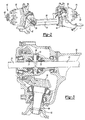
- FIG. 2 A perspective view of the inverted portal drive axle assembly 12 is shown in Figure 2.
- Each wheel end assembly 46, 48 defines a wheel axis of rotation 60 that is vertically higher relative to ground level than the axle shaft axis of rotation 54.
- the driving input power or torque is transferred from the input 26, at a vertically lower position, up to drive the wheel end assembly 46, 48, at a vertically higher position. This transfer is achieved by the use of the first 42 and second 44 wheel gear assemblies.
- the input 26 and differential gear assembly 36 are shown in greater detail in Figure 3.
- the input 26 includes a pinion gear 30 that drives a ring gear 34.
- a yoke assembly 62 couples a shaft 64, which supports the pinion gear 30, to the driveshaft 32.
- the ring gear 34 is bolted to a differential housing 66 that supports a four-legged spider 68 (only two legs are shown).
- a pinion gear 70 is supported on each leg of the spider 68.
- the pinion gears 70 mesh with side gears 72 that are splined to the axle shafts 38, 40.
- the first 42 and second 44 wheel gear assemblies are preferably helical gear assemblies that each include a helical pinion gear or wheel input drive gear 74 driven by one of the axle shafts 38, 40, see Figure 4.
- the input drive gear 74 is in meshing engagement with a pair of helical idler gears 76, which in turn are in meshing engagement with a helical driven gear or wheel output driven gear 78.
- the gears 74, 76, and 78 are enclosed within a gear housing 80 that is supported by the axle housing 58. It should be understood that the helical gear assembly shown in Figure 4 is just one example of a wheel gear assembly, and that other wheel gear assemblies known in the art could also be used.
- the output driven gears 78 drive the wheel shafts 82 that are coupled to the wheel hubs 50.
- the wheel shafts 82 define the wheel axes of rotation 60.
- the wheel gear assemblies 42, 44 raise the driving input from the vertically lower first 38 and second 40 axle shafts to the vertically higher wheel shafts 82.
- the wheel axes of rotation 60 are parallel to and spaced apart from the axle shaft axes of rotation 54, and are transverse to the longitudinal axis of rotation 52.
- the input drive gears 74 are coaxial with the axle shaft axes of rotation 54
- the output driven gears 78 are coaxial with the wheel axes of rotation 60.
- the wheel shafts 82 each include a cylindrical shaft body 84 that has a first end face 86 and a second end face 88.
- a laterally extending bore 90 forms a fluid passage within the shaft body 84 that is in fluid communication with the air supply 14.
- the bore 90 is preferably coaxial with the wheel axis of rotation 60 and extends through the entire length of the wheel shaft 82.
- the bore 90 has a fluid inlet 92 formed at the first end face 86, which is in fluid communication with the air supply 14.
- the bore 90 has a fluid outlet 94 formed at the second end face 88, which is in communication with the tire assembly 24.
- the fluid inlet 92 and the fluid outlet 94 are both coaxial with the bore 90.
- the second end face 88 includes a radially extending flange portion 96 that is mounted to an end face of the wheel hub 50 with a plurality of fasteners 98.
- the wheel hub 50 is rotatably supported by a pair of wheel bearings 100 for rotation relative to a non-rotating spindle 102, which is supported by the gear housing 80.
- a tee connection and hose assembly 104 is mounted to the second end face 88 of the wheel shaft 82.
- the tee connection and hose assembly 104 transfers air from the bore 90 to the tire assembly 24.
- the tee connection and hose assembly 104 includes a threaded body portion 106 that is received within a threaded portion 108 of the wheel shaft 82. While a threaded attachment is preferred, any other connection and hose assembly known in the art and any known attachment method could be used to form the air connection from the second end face 88 to the tire assembly 24.
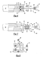
- An air supply component assembly 110 is used to interconnect the air supply 14 to the first end face 86 of the wheel shaft 82.
- the air supply component assembly 110 includes a tube 112 mounted for rotation with the wheel shaft 82, a pair of resilient seals 114 mounted within the tube 112, and an air supply needle 116 mounted to a non-rotating wheel or axle component such as the axle housing 58.
- the tube 112 includes a threaded end portion 118 that is threaded into a secondary bore 120 formed within the first end face 86 of the wheel shaft 82.
- the secondary bore 120 has a larger diameter than bore 90.
- the air supply needle 116 includes a threaded base portion 122 that is attached to the axle housing 58 and a hollow needle portion 124 that extends from the base portion 122.
- the needle portion 124 extends into the tube 112 and is resiliently engaged by the seals 114.
- This configuration provides a sealed rotary connection to transfer air from a non-rotating component to a rotating component. Further, the configuration accomplishes the air transfer without having to drill fluid passages in the wheel hub 50 or spindle 102.
- the air supply component assembly 130 includes a resilient gland seal 132 that is received within a secondary bore 134 formed within the first end face 86 of the wheel shaft 82.
- the secondary bore 134 is coaxial and of larger diameter than bore 90.
- the secondary bore 134 includes a threaded portion 136 and a seal seat portion 138.
- a gland nut 140 defining a central bore 142, has an external threaded portion 144 that mates with bore threaded portion 136.
- the gland seal 132 is seated on the seat portion 138 and is held in place by the gland nut 140.
- the gland seal 132 and gland nut 140 are mounted for rotation with the wheel shaft 82.
- An air supply needle 146 is mounted to the axle housing 58.
- the air supply needle 146 includes a threaded base portion 148 that is attached to the axle housing 58 and a hollow needle portion 150 that extends from the base portion 148.
- the needle portion 150 extends through the central bore 142 and into bore 90.
- the needle portion 150 pierces or is inserted through a small opening formed within the gland seal 132 such that the gland seal 132 resiliently engages the needle portion 150 to provide a sealed rotary connection. Air flows from the air supply 14, through the hose pressure lines 20, through the needle portion 150, and into the bore 90.
- the air supply component assembly 160 includes a seal body 162 that is received within a secondary bore 164 formed in the first end face 82 of the wheel shaft 82.
- the secondary bore 164 is coaxial with and is larger in diameter than bore 90.
- the seal body 162 is mounted for rotation with the wheel shaft 82 and includes an external seal 166 positioned between the seal body 162 and secondary bore walls 168.
- the seal body 162 defines an internal bore 170 that is in fluid communication with bore 90.
- a pair of seals 172 is mounted within the internal bore 170.
- An air supply needle 174 is mounted to the axle housing 58.
- the air supply needle 174 includes a threaded base portion 176 that is attached to the axle housing 58 and a hollow needle portion 178 that extends from the base portion 176.
- the needle portion 178 extends through the internal bore 170 and into bore 90.
- the needle portion 178 resiliently engages seals 172 to provide a sealed rotary connection. Air flows from the air supply 14, through the hose pressure lines 20, through the needle portion 178, and into the bore 90.
- the seal body 162 includes an external groove or channel 180 that is circumferentially formed about an external surface 182 of the seal body 162.
- the external seal 166 is received within the channel 180.
- a pair of internal grooves or channels 184 is circumferentially formed within bore walls 186 of the seal body 162.
- the seals 172 are received within these channels 184.
- the external seal 166 is a large o-ring seal and the seals 172 comprise smaller o-ring seals, however, other similar types of seals known in the art could also be used.
- a snap ring 188 holds the seal body 162 in place.
- Figures 5-8 show various examples of air supply component assemblies, it should be understood that other air supply component assemblies could also be used to provide a sealed rotary connection between the non-rotating axle housing 58 and the rotating wheel shaft 82.
- a simple method of providing a CTI system 10 for an inverted portal drive axle is achieved.
- the interface between the bore 90 and the air supply 14 can be simply and easily installed in this configuration.
- the relatively short wheel shaft 82 is used to provide a single, easily sealed bore 90 for conventional spindle configurations or unitized wheel bearing configurations.
- the system 10 is simple to maintain, requiring no removal of the wheel hub 50 to repair or replace any CTI component.
- the subject invention utilizes components that are small, simple, and inexpensive.
Landscapes
- Engineering & Computer Science (AREA)
- Mechanical Engineering (AREA)
- Tires In General (AREA)
- Braking Arrangements (AREA)
Applications Claiming Priority (2)
| Application Number | Priority Date | Filing Date | Title |
|---|---|---|---|
| US10/765,291 US7185688B2 (en) | 2004-01-27 | 2004-01-27 | Central tire inflation system for drive axle |
| US765291 | 2004-01-27 |
Publications (2)
| Publication Number | Publication Date |
|---|---|
| EP1559591A2 true EP1559591A2 (de) | 2005-08-03 |
| EP1559591A3 EP1559591A3 (de) | 2006-05-10 |
Family
ID=34654316
Family Applications (1)
| Application Number | Title | Priority Date | Filing Date |
|---|---|---|---|
| EP05250144A Withdrawn EP1559591A3 (de) | 2004-01-27 | 2005-01-13 | Zentrale Reifendruckregelanlage für eine Antriebsachse |
Country Status (3)
| Country | Link |
|---|---|
| US (1) | US7185688B2 (de) |
| EP (1) | EP1559591A3 (de) |
| CN (1) | CN100393538C (de) |
Cited By (2)
| Publication number | Priority date | Publication date | Assignee | Title |
|---|---|---|---|---|
| GB2477816A (en) * | 2010-02-12 | 2011-08-17 | Supacat Ltd | Central tyre inflation systems |
| GB2516704B (en) * | 2013-07-30 | 2016-02-10 | Jaguar Land Rover Ltd | Vehicle wheel assembly |
Families Citing this family (26)
| Publication number | Priority date | Publication date | Assignee | Title |
|---|---|---|---|---|
| FR2889111B1 (fr) * | 2005-07-26 | 2007-10-19 | Peugeot Citroen Automobiles Sa | Systeme de determination de la pression de gonflage de pneumatiques montes sur des roues avant et arriere d'un vehicule automobile |
| US7931061B2 (en) * | 2008-12-15 | 2011-04-26 | Arvinmeritor Technology, Llc | Tire inflation system with integrated wheel seal |
| US8869850B2 (en) * | 2010-01-25 | 2014-10-28 | Fleet Technologies, LLC | Axle to axle sealed airway for an onboard automatic tire inflation system |
| US8327895B2 (en) * | 2010-01-25 | 2012-12-11 | Fleet Technologies Llc | Drive axle seal body and tire inflation system |
| BR112013012298B1 (pt) | 2010-11-19 | 2020-04-28 | Equalaire Systems Inc | sistema de gerenciamento de pneu e método para gerenciar pressão de pneu |
| CN102069680A (zh) * | 2011-01-06 | 2011-05-25 | 中国重汽集团济南动力有限公司 | 一种轮胎中央充放气结构用桥 |
| DE102011007231B4 (de) * | 2011-04-12 | 2013-09-26 | Saf-Holland Gmbh | Radlageranordnung, insbesondere Radlageranordnung für Nutzfahrzeuge |
| CN103596780B (zh) | 2011-06-07 | 2016-06-08 | 伊夸莱尔系统公司 | 使用减压阀的系统和方法 |
| US8746305B2 (en) | 2011-06-15 | 2014-06-10 | Arvinmeritor Technology, Llc | Rotating seal assembly for tire inflation system |
| US8616254B2 (en) | 2011-09-23 | 2013-12-31 | Arvinmeritor Technology, Llc | Wheel hub with air passage for tire inflation system |
| US10059156B2 (en) | 2012-04-09 | 2018-08-28 | Dana Heavy Vehicle Systems Group, Llc | Hub assembly for a tire inflation system |
| US9636954B2 (en) | 2013-03-15 | 2017-05-02 | Servitech Industries, Inc. | Tire air pressure maintenance device |
| EP2969600B1 (de) | 2013-03-15 | 2017-05-03 | Dana Heavy Vehicle Systems Group, LLC | Anordnung |
| US9789739B1 (en) | 2013-04-23 | 2017-10-17 | Equalaire Systems, Inc. | Small trailer tire inflation system |
| CN103419579A (zh) * | 2013-08-05 | 2013-12-04 | 东南(福建)汽车工业有限公司 | 一种汽车行车胎压控制装置 |
| EP3530494B1 (de) * | 2013-11-11 | 2021-05-26 | Equalaire Systems, Inc. | Drehverbindung für reifenaufpumpsystem |
| US9457624B2 (en) * | 2014-10-22 | 2016-10-04 | Deere & Company | Variable tread axle assembly for tire inflation system |
| US10562357B2 (en) | 2015-06-12 | 2020-02-18 | Dana Heavy Vehicle Systems Group, Llc | Rotary joint air collector ring and the tire inflation system made therewith |
| US10556469B2 (en) | 2015-09-17 | 2020-02-11 | Dana Heavy Vehicle Systems Group, Llc | Hub cap assembly and a wheel end assembly for a tire inflation system |
| ES2940419T3 (es) | 2016-10-19 | 2023-05-08 | Pressure Systems Int Llc | Colector de inflado |
| DE102017104346B4 (de) * | 2017-03-02 | 2019-08-14 | Saf-Holland Gmbh | Druckluftsystem für Lenkachsen |
| FR3068300B1 (fr) * | 2017-06-30 | 2019-08-16 | Poclain Hydraulics Industrie | Appareil hydraulique ameliore comprenant une conduite pour la circulation d'air |
| US9925835B1 (en) * | 2017-08-21 | 2018-03-27 | Wharton Vision, Llc | Automatic tire inflation system with removable air conduit member |
| US11179976B2 (en) | 2019-05-14 | 2021-11-23 | Cnh Industrial America Llc | Work vehicle with partially rotatable tire inflation pack |
| US11454322B2 (en) | 2019-06-04 | 2022-09-27 | Fairfield Manufacturing Company, Inc. | Rotary pneumatic seal for a central tire inflation system |
| CN114044017B (zh) * | 2021-11-10 | 2023-03-10 | 东风悦享科技有限公司 | 一种抱轨式轨道车辆转向结构、轨道车辆 |
Family Cites Families (47)
| Publication number | Priority date | Publication date | Assignee | Title |
|---|---|---|---|---|
| US839626A (en) * | 1905-12-14 | 1906-12-25 | Carl Nielsen | Device for inflating the pneumatic tires of vehicles. |
| US1794900A (en) * | 1929-05-18 | 1931-03-03 | Rutherford H Hutchinson | Tire-inflating mechanism |
| US2908241A (en) | 1955-01-03 | 1959-10-13 | Gen Motors Corp | Amphibious vehicle |
| DE1505295A1 (de) * | 1965-12-23 | 1969-08-14 | Auto Union Gmbh | Hinterachse,insbesondere fuer Kraftfahrzeuge |
| JPS5241327A (en) * | 1975-09-29 | 1977-03-30 | Yasuo Tsuruta | Method of and apparatus for remote-controlling internal pressure of pn eumatic tyre installed on ... |
| US4387931A (en) * | 1981-04-13 | 1983-06-14 | The Budd Company | Tire pressure control in a vehicle |
| DE3127646A1 (de) | 1981-07-13 | 1983-04-14 | Daimler-Benz Ag, 7000 Stuttgart | "zentral durch die radnabe eines kraftfahrzeuges gelegte luftfuehrung fuer eine reifendruckregelanlage" |
| US4431043A (en) * | 1981-07-31 | 1984-02-14 | Am General Corporation | Automatic tire inflation system |
| US4498709A (en) * | 1983-06-30 | 1985-02-12 | Rockwell International Corporation | Axle for use with a tire inflation system |
| US4700763A (en) * | 1984-03-29 | 1987-10-20 | The United States Of America As Represented By The Secretary Of The Air Force | Remotely controlled aircraft tire inflation/deflation valve |
| US4582107A (en) * | 1984-07-26 | 1986-04-15 | The United States Of America As Represented By The Secretary Of The Army | Vehicle tire inflation-deflation mechanism |
| US4641698A (en) | 1984-11-08 | 1987-02-10 | Am General Corporation | Automated vehicle tire pressurization system |
| US4733707A (en) * | 1985-03-18 | 1988-03-29 | Am General Corporation | Vehicle wheel end assembly |
| DE3619603A1 (de) * | 1985-06-21 | 1987-01-02 | Volkswagen Ag | Einrichtung zur druckeinstellung in einem fahrzeugreifen |
| US4702843A (en) | 1985-06-21 | 1987-10-27 | Standard Manufacturing Co., Inc. | Control system for an adverse terrain vehicle |
| US4730656A (en) * | 1985-07-08 | 1988-03-15 | Am General Corporation | Vehicle wheel end assembly |
| US5236028A (en) * | 1985-07-08 | 1993-08-17 | Am General Corporation | Vehicle wheel end assembly |
| DE3618827A1 (de) | 1986-06-04 | 1987-12-10 | Daimler Benz Ag | Schaltventil zur beeinflussung des reifendruckes eines fahrzeugrades |
| US4844138A (en) * | 1986-09-01 | 1989-07-04 | Kabushiki Kaisha Tokai Rika Denki Seisakusho | Automobile tire pneumatic pressure controlling apparatus |
| US4883106A (en) * | 1989-01-19 | 1989-11-28 | Eaton Corporation | Rotary wheel-end assembly for tire inflation system |
| US4932451A (en) * | 1989-01-26 | 1990-06-12 | General Motors Corporation | Vehicle wheel end assembly with air passage |
| JPH0410783A (ja) * | 1990-04-27 | 1992-01-14 | Hitachi Ltd | ビデオカメラ装置 |
| EP0457028B1 (de) * | 1990-05-17 | 1995-12-20 | Equalaire Systems, Inc. | Luftkontrollsystem für Fahrzeugreifen |
| US5273064A (en) | 1991-09-03 | 1993-12-28 | Eaton Corporation | Vehicle central tire inflation system |
| US5253687A (en) | 1991-09-03 | 1993-10-19 | Eaton Corporation | Vehicle central tire inflation system |
| US5244027A (en) * | 1991-09-03 | 1993-09-14 | Eaton Corporation | Vent for vehicle tire inflation system |
| US5429167A (en) * | 1993-08-13 | 1995-07-04 | Oshkosh Truck Corporation | Universal central tire inflation system for trailers |
| US5377736A (en) * | 1993-11-18 | 1995-01-03 | Marks-Rms, Inc. | Driven axle vehicle inflation system |
| US5584949A (en) * | 1994-05-06 | 1996-12-17 | Ingram; Anthony L. | Air inflation system for trailer axles |
| US5538062A (en) * | 1994-08-12 | 1996-07-23 | Marks-Rms, Inc. | Pnuematic tire inflation system |
| US6122996A (en) * | 1998-11-20 | 2000-09-26 | Hydro-Gear Limited Partnership | Hydrostatic transmission |
| US5769979A (en) * | 1996-08-30 | 1998-06-23 | Equalaire Systems, Inc. | Rotary air connection for tire inflation system |
| US5868881A (en) * | 1996-09-04 | 1999-02-09 | Equalaire Systems, Inc. | Rotary air coupling for tire inflation system |
| US5767398A (en) * | 1996-11-20 | 1998-06-16 | Equalaire Systems, Inc. | Tire leak detector for an automatic inflation system |
| US6105645A (en) * | 1998-05-14 | 2000-08-22 | Ingram; Anthony L. | Rotary union assembly for use in air pressure inflation systems for tractor trailer tires |
| US6131631A (en) * | 1999-05-10 | 2000-10-17 | Equalaire Systems, Inc. | Press plug support for tire inflation system |
| AU5910400A (en) | 1999-07-02 | 2001-01-22 | Pressure Guard, Inc. | On-axle tire inflation system |
| US6244316B1 (en) * | 1999-07-16 | 2001-06-12 | Vehicle Inflation Technologies, Inc | Vehicle tire inflation system |
| US6260595B1 (en) * | 1999-08-04 | 2001-07-17 | Meritor Heavy Vehicle Systems, Llc | Unitized hub cap |
| US6145559A (en) * | 1999-09-03 | 2000-11-14 | Accessio, Ltd. | Axle and hub assembly for automatic tire inflation pressurization system |
| US6283186B1 (en) | 1999-11-23 | 2001-09-04 | Dana Corporation | Tire inflation system for live spindle wheel end |
| US6325124B1 (en) * | 2000-02-03 | 2001-12-04 | Col-Ven S.A. | Pneumatic rotary wheel coupling |
| US6269691B1 (en) * | 2000-03-17 | 2001-08-07 | Equalaire Systems, Inc | Automatic tire inflation system with booster pump |
| US6435238B1 (en) * | 2001-03-22 | 2002-08-20 | Equalaire Systems, Inc. | Combination of an automatic tire inflation system and anti-locking braking system |
| US6394159B1 (en) * | 2001-01-26 | 2002-05-28 | Meritor Heavy Vehicle Technology, Llc | Hub cap filter for tire inflation system |
| CN1394765A (zh) * | 2002-08-06 | 2003-02-05 | 中国重型汽车集团有限公司 | 重型越野汽车的轮胎中央充放气系统 |
| US6676228B1 (en) * | 2002-08-09 | 2004-01-13 | Arvinmeritor Technology, Llc | Vehicle wheel end assembly with support tube |
-
2004
- 2004-01-27 US US10/765,291 patent/US7185688B2/en not_active Expired - Lifetime
-
2005
- 2005-01-13 EP EP05250144A patent/EP1559591A3/de not_active Withdrawn
- 2005-01-20 CN CNB2005100022571A patent/CN100393538C/zh not_active Expired - Fee Related
Cited By (3)
| Publication number | Priority date | Publication date | Assignee | Title |
|---|---|---|---|---|
| GB2477816A (en) * | 2010-02-12 | 2011-08-17 | Supacat Ltd | Central tyre inflation systems |
| GB2516704B (en) * | 2013-07-30 | 2016-02-10 | Jaguar Land Rover Ltd | Vehicle wheel assembly |
| US9878586B2 (en) | 2013-07-30 | 2018-01-30 | Jaguar Land Rover Limited | Vehicle wheel assembly |
Also Published As
| Publication number | Publication date |
|---|---|
| CN1647959A (zh) | 2005-08-03 |
| EP1559591A3 (de) | 2006-05-10 |
| US20050161136A1 (en) | 2005-07-28 |
| US7185688B2 (en) | 2007-03-06 |
| CN100393538C (zh) | 2008-06-11 |
Similar Documents
| Publication | Publication Date | Title |
|---|---|---|
| US7185688B2 (en) | Central tire inflation system for drive axle | |
| US8397774B2 (en) | Tire inflation system with integrated wheel seal | |
| US8915274B2 (en) | Spindle for controlling wheel end endplay and preload | |
| US7690412B1 (en) | Drive axle with air passage for tire inflation system | |
| US6325123B1 (en) | Tire inflation system for a steering knuckle wheel end | |
| US7207365B2 (en) | Central tire inflation system rotary air union | |
| US10272728B2 (en) | Central tire inflation system rotary air union | |
| US9126460B2 (en) | Tire inflation system having a sleeve shaped air passage | |
| US9908373B2 (en) | Rotary air connection with central valve for tire inflation system | |
| US4932451A (en) | Vehicle wheel end assembly with air passage | |
| EP1234690B1 (de) | Fahrzeugrad mit Endanordnung | |
| US11718127B2 (en) | Axle assembly with internal lubrication system | |
| US6283186B1 (en) | Tire inflation system for live spindle wheel end | |
| EP2768683B1 (de) | Drehbare welle mit einer fluidleitung | |
| JPH02227302A (ja) | 回転ホイールエンド組立体 | |
| US8327895B2 (en) | Drive axle seal body and tire inflation system | |
| RU154956U1 (ru) | Колесный узел с устройством подвода воздуха к шине | |
| WO2026008691A1 (en) | Rotor with improved airtightness and venting for tire calibration assemblies | |
| HK1185130B (en) | Rotary air connection with central valve for tire inflation system |
Legal Events
| Date | Code | Title | Description |
|---|---|---|---|
| PUAI | Public reference made under article 153(3) epc to a published international application that has entered the european phase |
Free format text: ORIGINAL CODE: 0009012 |
|
| AK | Designated contracting states |
Kind code of ref document: A2 Designated state(s): AT BE BG CH CY CZ DE DK EE ES FI FR GB GR HU IE IS IT LI LT LU MC NL PL PT RO SE SI SK TR |
|
| AX | Request for extension of the european patent |
Extension state: AL BA HR LV MK YU |
|
| PUAL | Search report despatched |
Free format text: ORIGINAL CODE: 0009013 |
|
| AK | Designated contracting states |
Kind code of ref document: A3 Designated state(s): AT BE BG CH CY CZ DE DK EE ES FI FR GB GR HU IE IS IT LI LT LU MC NL PL PT RO SE SI SK TR |
|
| AX | Request for extension of the european patent |
Extension state: AL BA HR LV MK YU |
|
| 17P | Request for examination filed |
Effective date: 20061121 |
|
| R17P | Request for examination filed (corrected) |
Effective date: 20061121 |
|
| AKX | Designation fees paid |
Designated state(s): DE FR GB IT SE |
|
| R17P | Request for examination filed (corrected) |
Effective date: 20061110 |
|
| STAA | Information on the status of an ep patent application or granted ep patent |
Free format text: STATUS: THE APPLICATION IS DEEMED TO BE WITHDRAWN |
|
| 18D | Application deemed to be withdrawn |
Effective date: 20090606 |