EP1559491B1 - Bohrmaschinenfutter - Google Patents
Bohrmaschinenfutter Download PDFInfo
- Publication number
- EP1559491B1 EP1559491B1 EP03753220A EP03753220A EP1559491B1 EP 1559491 B1 EP1559491 B1 EP 1559491B1 EP 03753220 A EP03753220 A EP 03753220A EP 03753220 A EP03753220 A EP 03753220A EP 1559491 B1 EP1559491 B1 EP 1559491B1
- Authority
- EP
- European Patent Office
- Prior art keywords
- sleeve
- nut
- keys
- jaws
- elastic
- Prior art date
- Legal status (The legal status is an assumption and is not a legal conclusion. Google has not performed a legal analysis and makes no representation as to the accuracy of the status listed.)
- Expired - Lifetime
Links
Images


Classifications
-
- B—PERFORMING OPERATIONS; TRANSPORTING
- B23—MACHINE TOOLS; METAL-WORKING NOT OTHERWISE PROVIDED FOR
- B23B—TURNING; BORING
- B23B31/00—Chucks; Expansion mandrels; Adaptations thereof for remote control
- B23B31/02—Chucks
- B23B31/10—Chucks characterised by the retaining or gripping devices or their immediate operating means
- B23B31/12—Chucks with simultaneously-acting jaws, whether or not also individually adjustable
- B23B31/1207—Chucks with simultaneously-acting jaws, whether or not also individually adjustable moving obliquely to the axis of the chuck in a plane containing this axis
- B23B31/1238—Jaws movement actuated by a nut with conical screw-thread
-
- B—PERFORMING OPERATIONS; TRANSPORTING
- B23—MACHINE TOOLS; METAL-WORKING NOT OTHERWISE PROVIDED FOR
- B23B—TURNING; BORING
- B23B2231/00—Details of chucks, toolholder shanks or tool shanks
- B23B2231/38—Keyless chucks for hand tools
-
- Y—GENERAL TAGGING OF NEW TECHNOLOGICAL DEVELOPMENTS; GENERAL TAGGING OF CROSS-SECTIONAL TECHNOLOGIES SPANNING OVER SEVERAL SECTIONS OF THE IPC; TECHNICAL SUBJECTS COVERED BY FORMER USPC CROSS-REFERENCE ART COLLECTIONS [XRACs] AND DIGESTS
- Y10—TECHNICAL SUBJECTS COVERED BY FORMER USPC
- Y10S—TECHNICAL SUBJECTS COVERED BY FORMER USPC CROSS-REFERENCE ART COLLECTIONS [XRACs] AND DIGESTS
- Y10S279/00—Chucks or sockets
- Y10S279/902—Keyless type socket
-
- Y—GENERAL TAGGING OF NEW TECHNOLOGICAL DEVELOPMENTS; GENERAL TAGGING OF CROSS-SECTIONAL TECHNOLOGIES SPANNING OVER SEVERAL SECTIONS OF THE IPC; TECHNICAL SUBJECTS COVERED BY FORMER USPC CROSS-REFERENCE ART COLLECTIONS [XRACs] AND DIGESTS
- Y10—TECHNICAL SUBJECTS COVERED BY FORMER USPC
- Y10T—TECHNICAL SUBJECTS COVERED BY FORMER US CLASSIFICATION
- Y10T279/00—Chucks or sockets
- Y10T279/17—Socket type
- Y10T279/17615—Obliquely guided reciprocating jaws
- Y10T279/17623—Threaded sleeve and jaw
- Y10T279/17632—Conical sleeve
-
- Y—GENERAL TAGGING OF NEW TECHNOLOGICAL DEVELOPMENTS; GENERAL TAGGING OF CROSS-SECTIONAL TECHNOLOGIES SPANNING OVER SEVERAL SECTIONS OF THE IPC; TECHNICAL SUBJECTS COVERED BY FORMER USPC CROSS-REFERENCE ART COLLECTIONS [XRACs] AND DIGESTS
- Y10—TECHNICAL SUBJECTS COVERED BY FORMER USPC
- Y10T—TECHNICAL SUBJECTS COVERED BY FORMER US CLASSIFICATION
- Y10T279/00—Chucks or sockets
- Y10T279/20—Chucks or sockets with safety feature
-
- Y—GENERAL TAGGING OF NEW TECHNOLOGICAL DEVELOPMENTS; GENERAL TAGGING OF CROSS-SECTIONAL TECHNOLOGIES SPANNING OVER SEVERAL SECTIONS OF THE IPC; TECHNICAL SUBJECTS COVERED BY FORMER USPC CROSS-REFERENCE ART COLLECTIONS [XRACs] AND DIGESTS
- Y10—TECHNICAL SUBJECTS COVERED BY FORMER USPC
- Y10T—TECHNICAL SUBJECTS COVERED BY FORMER US CLASSIFICATION
- Y10T279/00—Chucks or sockets
- Y10T279/32—Means to prevent jaw loosening
Definitions
- the present invention relates to a clamping device for drilling tools, and particularly to a power drill chuck according to the preamble of claim 1 and as known from WO 98/14294 .
- a manually tightened drill chuck in the present art generally includes a drill body, jaws, a nut, a nut sleeve, a bearing, a front sleeve, and a rear sleeve.
- the three jaws are mounted respectively in three inclined holes that are trisection of said drill body.
- the nut is mounted in a nut slot of the drill body.
- the nut thread constitutes a thread drive mechanism together with the thread of the jaws.
- the nut sleeve is fixedly connected with the nut. Between the front sleeve and the nut or the nut sleeve a key type connection is adopted.
- the rear sleeve is fixedly connected with the drill body that is provided with a threaded hole or a tapered hole on its rear portion.
- the drill body is connected with a drive shaft screw of power machine by the threaded hole at its rear portion.
- the drive shaft drives the drill body and thereby brings the three jaws and the tool being clamped to rotate synchronously.
- the front sleeve and the rear sleeve are grasped by hands and are rotated from each other so that the nut connected with the front sleeve rotates relative to the jaws in the drill body.
- the jaws are moved forwards along the inclined holes of the drill body to clamp the tool handle.
- WO 98/14294 discloses a chuck for use with a driver having a rotatable shaft including a body and jaws slidably positioned in angled passageways formed in the body.
- the chuck further includes a nut rotatably mounted relative to the body and in engagement with threads on the jaws.
- a generally cylindrical sleeve member is disposed in driving engagement with the nut and overlying the nose section of the body so that when the sleeve member is rotated with respect to the body, the jaws will be moved thereby to grip the shank of a tool.
- a pawl member is biased to engage the sleeve member and is disposed selectively rotatably with respect to the body. When the nut is tightened, the pawl member can be disposed to become nonrotatable with respect to the body and restrains the nut from loosening during vibration of the chuck in use.
- the chuck can be manually operated or electrically driven. However this kind of chuck still suffers from the problem in which the clamped tool tends to get loosen when the working resistance is larger.
- the patent US005988653A disclosed a clamping device that clamps the tool handle in virtue of the power of the electric tool. However, the structure of the device is much complex.
- the technical object of the present invention is to provide a power drill chuck that has simple structures and is convenient to use, and through which a power tightened clamp can be obtained and the clamp is secure.
- the present invention provides a power drill chuck including a drill body, a nut, jaws, a front sleeve, a rear sleeve, a nut sleeve, and a rolling body, wherein the three jaws are mounted respectively in three inclined holes which are trisection of the drill body, the nut thread constitutes a thread drive mechanism together with the thread of the jaws mounted in the three inclined holes of the drill body, the front sleeve is fixedly connected with the drill body, which is characterized in that the nut sleeve is fixedly connected with the nut and extends backwards, in the rear end of which a plurality of projecting key are provided, the rear sleeve is mounted around the rear portion of the nut sleeve and can be
- the location ring provided in the rear sleeve and the rear portion of the drill body, the location ring is provided with a plurality of connecting keys and connecting holes.
- an anti-friction ring or bearing provided between an exterior wall of the nut sleeve and an inner wall of the rear sleeve.
- the drill body of the drill chuck is connected with the drive shaft of the electric drill and can rotate synchronously with it. While using, the drive shaft drives the drill body and the jaws to rotate; the rear sleeve is gripped with hands to keep immovable.
- a location ring can also be mounted between the rear sleeve and the front end of the electric drill to locate and fixed at the front end of the electric drill.
- the location ring is provided with keys that restrict the rear sleeve to rotate relative to the location ring only in a certain angle and not to rotate at both extreme position of the angle.
- the nut and the nut sleeve are fixedly connected, the slopes of the projecting keys at the rear end of the nut sleeve and the slopes of the projecting keys of the elastic impact member get in contact with each other, and the elastic impact member is connected to the rear sleeve, thereby the nut are prevented from rotating so that a relative rotation occurs between the jaws and the nut.
- the jaws are closed until the jaws contact the tool handle to be clamped.
- the resistance to the thread drive of the nut and the jaws increases rapidly, and the slopes of the projecting keys at the rear end of the nut sleeve and the slopes of the projecting keys of the elastic impact member are pressed against each other, so that the elastic impact member is forced to overcome the resilience of the elastic deformation portion and moves along the slopes of the projecting keys until the tops of the both projecting keys are in contact, and subsequently, the tops of the both projecting keys slide relatively and run out of in contact, in this manner, the nut and the jaws are rotated synchronously.
- the drill body, the jaws, the nut, and the nut sleeve Being driven by the rotating torque of the drive shaft of the electric hand drill, the drill body, the jaws, the nut, and the nut sleeve rotate synchronously together with the drive shaft of the electric hand drill, and at the same time, the elastic impact member returns reversely to its original position again owing to the elasticity of the elastic deformation portion, such that while moving, the slopes of the projecting keys of the nut sleeve come into impact with the slopes of the projecting key of the elastic impact member. Under the effect of impact a slight relative rotation occurs between the nut and the jaws so that the jaws can clamp the tool handle more firmly.
- the elastic impact member is forced to overcome the resilience of the elastic deformation portion such that the both projecting keys are out of contact again due to the impact force between the slopes of the both projecting keys.
- the drive shaft of the electric hand drill rotates continuously, the impact course is repeated continuously, and thereby the tool handle is clamped firmly by the jaws.
- the drive shaft of the electric hand drill are driven to rotate reversely, the slopes of the projecting keys of the nut sleeve and the slopes of the projecting keys of the elastic impact member impact and disengage from each other repeatedly in reverse direction until the threads of the nut and the jaws move relatively to loosen the tool handle being clamped.
- An anti friction ring or a bearing may be mounted between the stationary rear sleeve and the rotational nut sleeve to keep the nut sleeve to rotate agilely along with the drill body.
- the drill chuck according to the present invention has a powered clamping function, such that the gripping power for handle of the tool is improved to ensure the clamp secure.
- the present invention is suitable for all kinds of clamping of drilling tool.
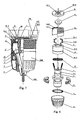
- a power drill chuck which includes a drill body 1 , a nut sleeve 2 , a nut 3 , jaws 4 , an elastic impact member 5 , a rear sleeve 6 , a rolling body 7 , a positioning sleeve 8 , and a front sleeve 9 .
- the three jaws 4 are mounted respectively in three inclined holes which are trisection of the drill body.
- the thread of the nut 3 constitutes a thread drive together with the thread of the jaws 4 mounted in the three inclined holes of the drill body.
- the front sleeve 9 is fixedly connected to the drill body 1.
- the nut sleeve 2 is fixedly connected to the nut 3 and extends backwards, in its rear end a plurality of projecting keys 2-1 are provided.
- the rear sleeve 6 is mounted around the rear portion of the nut sleeve 2 and can rotate relative to the nut sleeve and the drill body.
- the positioning sleeve 8 is fixedly connected to the rear portion of the drill body 1 so as to position the rear sleeve axially on the drill body.
- a plurality of elastic impact members 5 is mounted between the nut sleeve and the rear sleeve.
- the elastic impact members are provided with a plurality of deformation portions 5-3 and a plurality of projecting keys 5-2.
- the power drill chuck is connected to the screw of the drive shaft of an electric portable drill through a thread hole in the rear portion of the drill chuck.
- the positioning sleeve 8 is fixedly connected to the rear portion 1-1 of the drill chuck 1 so as to position the rear sleeve 6 axially on the drill body 1 .
- the rear sleeve can rotate with respect to the drill body 1 and the positioning sleeve 8.
- On the inner end face of the rear sleeve 6 there are provided with a plurality of keys 6-1 to which the elastic impact members 5 are mounted by fitting parts 5-1 thereof.
- the elastic impact members 5 are provided with a plurality of deformation portions 5-3 and a plurality of projecting keys 5-2 .
- Both sides of the projecting key 5-2 in the directions along the circumference are slopes.
- the nut sleeve 2 is fixedly connected to the nut 3 and extends backwards, in rear end of which a plurality of projecting keys 2-1 are provided. Both sides of the projecting key 2-1 in the directions along the circumference are slopes.
- the nut sleeve 2 is also provided with an annular rib 2-2 projecting inwards for restricting the rolling bodies 7 assembled in the nut.
- the slopes of the projecting keys 5-2 of the elastic impact member 5 contacts the slopes of the projecting keys 2-1 of the nut sleeve 2 such that the rear sleeve rotates along with the nut sleeve 2.
- a tool is required to be clamped, one may grasps the rear sleeve 6 slightly and keeps the same to be immovable such that the elastic impact member 5 , the nut sleeve 2 and the nut 3 are immovable while the dill body 1 and the jaws 4 rotate along with the drive shaft of the electric drill.
- the projecting keys 2-1 of the nut sleeve and the projecting keys 5-2 of the elastic impact member slide relatively and run out of contact, and then the elastic impact member 5 returns to its original position again by its inherent elasticity.
- the nut sleeve 2 and the nut 3 rotate along with the jaws 4 and the drill body 1 so that the projecting keys 2-1 of the nut sleeve impact the projecting keys 5-2 of the elastic impact member.
- the nut sleeve 2 brings the nut 3 to get a slight relative rotation relative to the jaws 4 so that the clamping force to the tool handle 104 by the jaws 4 increases, and the impacting force obliges the projecting keys of the elastic impact member to retract again.
- the drive shaft of the electric hand drill When expecting to loosen the clamped tool 104, the drive shaft of the electric hand drill are required to be rotated reversely, and drive the drill body 1, the front sleeve 9, jaws 4, the nut 3, and the nut sleeve 2 to rotate reversely together.
- the rear sleeve 6 is grasped slightly by hand so that reverse impact repeatedly occurs between the projecting keys 2-1 of the nut sleeve and the projecting keys 5-2 of the elastic impact member. Under such repeated impact, the nut sleeve 2 brings the nut 3 to get a relative rotation relative to the jaws 4 to loosen the tool 104 .
- a power drill chuck which includes a drill body 1 , a nut sleeve 2 , a nut 3 , jaws 4 , an elastic impact member 55 , a rear sleeve 6 , a rolling body 7 , a positioning sleeve 8 , and a front sleeve 9.
- the elastic impact member 55 is dish-shaped and provided with a plurality of deformation portions 55-2 and a plurality of down-projected projecting keys 55-1 .
- the nut sleeve 2 is provided with upper-projected projecting keys 2-1 .
- Both sides of the down-projected projecting keys 55-1 of the elastic impact member and the upper-projected projecting keys 2-1 of the nut sleeve 2 in the directions along the circumferences thereof are slopes.
- the elastic impact member 55 is mounted on the projecting keys 6-1 of the rear sleeve through slots 55-3 such that the elastic impact member 55 may slide up and down along the projecting keys 6-1 of the rear sleeve under the effect of the elastic deformation portion 55-2 .
- the slopes of the projecting keys 55-1 of the elastic impact member 55 contact the slopes of projecting keys 2-1 of the nut sleeve 2 .
- the resistance for relatively rotating between the jaws 4 and the nut 3 and the press imposed on the slopes of the projecting keys 55-1 of the elastic impact member by the slopes of the projecting keys 2-1 of the nut sleeve increases rapidly, so that the elastic impact member 55 is forced to be deformed elastically at the elastic deformation portions 55-2 thereof and retracts backwards.
- the projecting keys 2-1 of the nut sleeve and the projecting keys 55-1 of the elastic impact member slide relatively and run out of contact, and then the elastic impact member 55 returns to its original position again by the elasticity of the elastic deformation portion 55-2.
- the nut sleeve 2 and the nut 3 continue to rotate along with the jaws 4 and the drill body 1 so that the projecting keys 2-1 of the nut sleeve impact the projecting keys 55-1 of the elastic impact member.
- the nut sleeve 2 brings the nut 3 and makes the same having a slight relative rotation relative to the jaws 4 and the clamping force to the tool handle 104 by the jaws 4 increases.
- the impacting force depresses the projecting keys of the elastic impact member to retract again. Such impact is repeated and continues until the tool handle 104 is clamped firmly by the jaws 4 . Then the grasp to the rear sleeve 6 can be relapsed and the rear sleeve will rotate along with the drill body such that the machining works can be done.
- the drive shaft of the electric hand drill When expecting to loose the clamped tool 104 , the drive shaft of the electric hand drill is required to be rotated reversely, and drive the drill body 1 , the front sleeve 9 , jaws 4 , the nut 3 , and the nut sleeve 2 to rotate reversely together.
- the rear sleeve 6 is grasped slightly by hand so that reverse impact repeatedly occurs between the projecting keys 2-1 of the nut sleeve and the projecting keys 5-1 of the elastic impact member. Under such repeated impact, the nut sleeve 2 brings the nut 3 and makes the same having a relative movement relative to the jaws 4 to loosen the tool 104 .
- the power drill chuck of the present invention may further include a location ring 10 at the rear sides of the rear sleeve 6 and the drill body 1 .
- the location ring is provided with a plurality of connection keys and connection holes.
- the power drill chuck which includes a drill body 1 , a nut sleeve 2 , a nut 3 , jaws 4 , an elastic impact member 5 , a rear sleeve 6 , rolling bodies 7 , a positioning sleeve 8 , a front sleeve 9 , a location ring 10 , and a bearing 12 .
- the location ring 10 While mounting the drill chuck to a electric hand drill, firstly the location ring 10 is fixed to a annular member 101 provided in the shield cup 103 of the electric hand drill through screws 102 with the connection keys 10-1 of the location ring 10 being inserted in the annular holes 6-2 of the rear sleeve 6 . Then the thread hole in the rear portion of the drill chuck is engaged with the screw of the drive shaft of the electric hand drill. The rear sleeve is rotated in normal direction such that the reversed side walls of the annular holes 6-2 of the rear sleeve contact the keys 10-1 of the location ring.
- the elastic impact member 5 is mounted on the projecting keys 6-1 of the rear sleeve through a fitting portion 5-1 such that the slopes of the projecting keys 5-2 of the elastic impact member 5 contact the slopes of the projecting keys 2-1 of the nut sleeve. Since the rear sleeve 6 is resisted by the connection keys 10-1 of the location ring and cannot move in normal direction, the nut sleeve 2 and the nut 3 cannot rotate in normal direction too as the contact of the projecting keys 5-2 of the elastic impact member and the projecting keys 2-1 of the nut sleeve.
- the switch of the electric hand drill is closed so that the drive shaft of the electric hand drill brings the drill body 1 , the jaws 4 and the front sleeve 9 to rotate together.
- the threads of the jaws 4 and the threads of the nut 3 form a thread drive, thereby, the jaws 4 move forwards along the inclined holes in the drill body 1 until the tool handle 104 is clamped.
- the press imposed on the slopes of the projecting keys 5-2 of the elastic impact member by the slopes of the projecting keys 2-1 of the nut sleeve increases rapidly so that the elastic impact member 5 is forced to be deformed elastically and retracts backwards relative to the projecting keys 2-1 of the nut sleeve to rotate the nut sleeve 2 and the nut 3 together with the jaws 4 and the drill body 1 .
- the projecting keys 2-1 of the nut sleeve travels over the projecting keys 5-2 of the elastic impact member, the projecting keys 5-2 of the elastic impact member 5 returns to its original position again by the elastic resilience.
- the nut sleeve 2 continues to rotate so that the projecting keys 2-1 impact the projecting keys 5-2 of the elastic impact member.
- the impact force generates a slight relative movement between the nut 3 and the jaws 4 and increases the clamping force to the tool handle 104 by the jaws 4 .
- the impact force oppresses the projecting keys of the elastic impact member to retract again, such impact is repeated and continues until the tool handle 104 is clamped firmly by the jaws 4.
- the fourth embodiment As shown in Figs. 9 and 11 , the illustrated is another power drill chuck in which the constituting structure is substantially the same as that of the third embodiment, and no descriptions will be made any more for the same parts.
- the projecting keys 55-1 and the elastic deformation portions 55-2 of the elastic impact member 55 take an end face-arranged structure.
- the projecting keys 55-1 are down-projected, as shown in Fig. 10 .
- the elastic impact member 55 is provided with cam curved surfaces 55-3 and 55-4 that is changed in the direction of the axis. Under the resilience of the elastic deformation portions 55-2 , the cam-curved surfaces 55-3 or 55-4 keeps in contact with the pawls 6-3 of the rear sleeve keys 6-1 all along.
- the projecting keys 2-1 of the nut sleeves 2 are also an end face-arranged structure and are upper-projected.
- Rolling bodies 13 are mounted between the nut sleeve 2 and the rear sleeve 6 .
- the drive shaft of the electric hand drill When expecting to remove the tool, the drive shaft of the electric hand drill is required to be rotated reversely.
- the projecting keys 2-1 of the nut sleeve impact the projecting keys 55-1 of the elastic impact member, and thereby, the nut 3 generates a reverse relative rotation relative to the jaws 4 to loosen the tool.
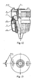
- the fifth embodiment As shown in Figs. 12 and 13 , the illustrated is a power drill chuck which includes a drill body 1 , a nut sleeve 2 , a nut 3 , jaws 4 , rolling bodies 7 , and a front sleeve 9 .
- the projecting keys 2-3 provided at the rear end face of the nut sleeve 2 can impact the impact projecting keys specially-designed in the electric hand drill so as to clamp the tool.
Landscapes
- Engineering & Computer Science (AREA)
- Mechanical Engineering (AREA)
- Gripping On Spindles (AREA)
- Drilling And Boring (AREA)
Claims (9)
- Bohrmaschinenfutter, umfassend einen Bohrkörper (1), eine Mutter (3), Einspannbacken (4), eine vordere Aufsteckhülse (9), eine hintere Aufsteckhülse (6), eine Mutterhülse (2) und einen Wälzkörper (7), wobei die drei Einspannbacken (4) in drei geneigten Löchern angebracht sind und eine Dreiteilung des Bohrkörpers (1) bewirken, und das Muttergewinde zusammen mit dem Gewinde der Einspannbacken (4), die in drei geneigten Löchern im Bohrkörper (1) angebracht sind, einen Gewindetrieb begründen, und die vordere Aufsteckhülse (9) fest mit dem Bohrkörper (1) verbunden ist, dadurch gekennzeichnet, dass die Mutterhülse (2) fest mit der Mutter (3) verbunden ist und sich nach rückwärts in ein hinteres Ende verlängert, auf dem eine Mehrzahl von hervorstehenden Halteelementen (2-1) vorhanden sind, die hintere Aufsteckhülse (6) um den hinteren Teil der Mutterhülse (2) montiert ist und relativ zur Mutterhülse (2) und zum Bohrkörper (1) rotieren kann, die Mutterhülse (2) auf ihrer rückseitigen Oberfläche mit stückweise ringförmigen Löchern (6-2) und eine Mehrzahl von Halteelementen (6-1) auf ihrer Innenoberfläche versehen ist, eine Stellhülse (8) fest am Ende des Bohrkörpers (1) angebracht ist, um die hintere Aufsteckhülse (6) axial am Bohrkörper (1) auszurichten, eine Mehrzahl von elastischen Anschlagelementen (5) zwischen der Mutterhülse (2) und der hintere Aufsteckhülse (6) angebracht sind, wobei die elastischen Anschlagselemente (5) mit einer Mehrzahl von elastischen Verformungs-Abschnitten (5-3) und einer eine Mehrzahl von hervorstehenden Halteelementen (5-2) versehen sind.
- Bohrmaschinenfutter nach Anspruch 1, dadurch gekennzeichnet, dass ein Positionierring (10) an der Rückseite der hinteren Aufsteckhülse (6) an dem Bohrkörper (1) vorhanden ist und der Positionierring (10) mit einer Mehrzahl von Verbindungselementen und Verbindungslöchern versehen ist.
- Bohrmaschinenfutter nach Anspruch 2, dadurch gekennzeichnet, dass ein Wälzring oder ein Wälzlager (12) zwischen der äußeren Wand der Mutterhülse (2) und der inneren Wand der hintere Aufsteckhülse (6) vorhanden ist.
- Bohrmaschinenfutter nach Anspruch 1 oder Anspruch 2, dadurch gekennzeichnet, dass beide Seitenoberflächen der hervorstehenden Halteelemente (5-2) am hinteren Ende der Mutterhülse (2) in Richtung der Peripherie geneigt sind.
- Bohrmaschinenfutter nach Anspruch 1 oder Anspruch 2, dadurch gekennzeichnet, dass das elastische Anschlagelement (5) auf den Halteelementen (6-1) der hinteren Aufsteckhülse (6) aufgebracht ist.
- Bohrmaschinenfutter nach Anspruch 1 oder Anspruch 2, dadurch gekennzeichnet, dass beide Seitenoberflächen der hervorstehenden Halteelemente (5-2) des elastischen Anschlagselements (5) in Richtung der Peripherie geneigt sind.
- Bohrmaschinenfutter nach Anspruch 1 oder Anspruch 2, dadurch gekennzeichnet, dass das elastische Anschlagelement (5) mit einer mit Nocken gewölbten Oberfläche ausgestattet ist, die sich in Richtung zur Achse des Bohrfutters hin ändert.
- Bohrmaschinenfutter nach Anspruch 1 oder Anspruch 2, dadurch gekennzeichnet, dass die elastischen Verformungs-Abschnitte (5-3) des elastischen Anschlagelements (5) separate elastische Verformungs-Abschnitte getrennt vom elastischen Anschlagelement sind.
- Bohrmaschinenfutter nach Anspruch 1 oder Anspruch 2, dadurch gekennzeichnet, dass die Halteelemente an der Innenseite hinteren Aufsteckhülse (6) mit Rasten (6-3) versehen sind.
Applications Claiming Priority (3)
| Application Number | Priority Date | Filing Date | Title |
|---|---|---|---|
| CNB021354901A CN100388994C (zh) | 2002-09-20 | 2002-09-20 | 动力夹紧钻夹头 |
| CN02135490 | 2002-09-20 | ||
| PCT/CN2003/000802 WO2004026512A1 (en) | 2002-09-20 | 2003-09-22 | A power drill chuck |
Publications (3)
| Publication Number | Publication Date |
|---|---|
| EP1559491A1 EP1559491A1 (de) | 2005-08-03 |
| EP1559491A4 EP1559491A4 (de) | 2008-10-15 |
| EP1559491B1 true EP1559491B1 (de) | 2012-11-07 |
Family
ID=32000615
Family Applications (1)
| Application Number | Title | Priority Date | Filing Date |
|---|---|---|---|
| EP03753220A Expired - Lifetime EP1559491B1 (de) | 2002-09-20 | 2003-09-22 | Bohrmaschinenfutter |
Country Status (5)
| Country | Link |
|---|---|
| US (1) | US7469908B2 (de) |
| EP (1) | EP1559491B1 (de) |
| CN (1) | CN100388994C (de) |
| AU (1) | AU2003272840A1 (de) |
| WO (1) | WO2004026512A1 (de) |
Families Citing this family (6)
| Publication number | Priority date | Publication date | Assignee | Title |
|---|---|---|---|---|
| CN2715890Y (zh) * | 2004-08-03 | 2005-08-10 | 山东威达机械股份有限公司 | 带响自锁式钻夹头 |
| CN100563942C (zh) * | 2004-09-17 | 2009-12-02 | 苏州宝时得电动工具有限公司 | 钻类电动工具 |
| CN100578036C (zh) * | 2005-09-28 | 2010-01-06 | 山东威达机械股份有限公司 | 单向离合装置及采用该装置的柄类工具夹持结构 |
| CN100475391C (zh) * | 2006-04-14 | 2009-04-08 | 浙江睿丰钻夹制造有限公司 | 手紧钻夹头的自锁机构 |
| CN201012399Y (zh) * | 2007-04-10 | 2008-01-30 | 浙江三鸥机械股份有限公司 | 一种新颖自锁式手紧钻夹头 |
| CN109746484B (zh) * | 2017-11-03 | 2024-06-14 | 苏州宝时得电动工具有限公司 | 动力工具 |
Family Cites Families (22)
| Publication number | Priority date | Publication date | Assignee | Title |
|---|---|---|---|---|
| US4669932A (en) * | 1985-05-24 | 1987-06-02 | Wayne Hartley | Keyless tool chuck |
| JPH0783961B2 (ja) * | 1991-06-13 | 1995-09-13 | ユキワ精工株式会社 | 工具用チャック |
| FR2702975B1 (fr) * | 1993-03-26 | 1995-06-16 | Amyot Ets Sa | Mandrin porte-outil pour l'equipement d'une machine tournante, telle qu'une perceuse. |
| US5348317A (en) * | 1993-08-13 | 1994-09-20 | Jacobs Chuck Technology Corporation | Chuck |
| DE4407854B4 (de) * | 1994-03-09 | 2008-03-27 | Röhm Gmbh | Bohrfutter |
| DE59606508D1 (de) * | 1996-01-17 | 2001-04-05 | Roehm Gmbh | Bohrfutter |
| DE19606795C2 (de) * | 1996-02-23 | 1998-01-22 | Metabowerke Kg | Bohrfutter |
| US5741016A (en) * | 1996-10-02 | 1998-04-21 | Power Tool Holders Incorporated | Chuck |
| US6007071A (en) * | 1998-03-09 | 1999-12-28 | Power Tool Holders Incorporated | Chuck with locking body |
| US5988653A (en) | 1998-06-18 | 1999-11-23 | Chum Power Machinery Corp. | Auto-locking bit holding system of a hand tool |
| US6196554B1 (en) * | 1998-12-15 | 2001-03-06 | Power Tool Holders Incorporated | Locking chuck |
| CN2376354Y (zh) * | 1999-06-30 | 2000-05-03 | 铨宝工业股份有限公司 | 冲击自锁式的夹头结构 |
| CN1145539C (zh) | 1999-09-21 | 2004-04-14 | 铨宝工业股份有限公司 | 搭配旋转轴使用的自锁式夹头 |
| US6729812B2 (en) | 1999-12-06 | 2004-05-04 | Theodore G. Yaksich | Power driver having geared tool holder |
| CN2414864Y (zh) * | 2000-04-10 | 2001-01-17 | 铨宝工业股份有限公司 | 夹头驱动轴新结构 |
| US6302407B1 (en) * | 2000-04-20 | 2001-10-16 | Chun Chu Hsueh | Chuck structure with locking and positioning functions |
| US6488286B2 (en) | 2000-08-21 | 2002-12-03 | Theodore G. Yaksich | Chuck and power driver having improved interface assembly |
| CN1217762C (zh) * | 2001-06-10 | 2005-09-07 | 山东威达机械股份有限公司 | 自锁钻夹头 |
| CN1220569C (zh) * | 2001-06-10 | 2005-09-28 | 山东威达机械股份有限公司 | 自紧钻夹头 |
| US6824141B1 (en) * | 2001-08-30 | 2004-11-30 | Yukiwa Seiko Kabushiki Kaisha | Chuck device |
| CN2576385Y (zh) * | 2002-11-04 | 2003-10-01 | 台州市超力机电有限公司 | 自锁式钻夹头 |
| CN2582790Y (zh) * | 2002-11-25 | 2003-10-29 | 山东威达机械股份有限公司 | 自锁钻夹头 |
-
2002
- 2002-09-20 CN CNB021354901A patent/CN100388994C/zh not_active Expired - Lifetime
-
2003
- 2003-09-22 AU AU2003272840A patent/AU2003272840A1/en not_active Abandoned
- 2003-09-22 US US10/528,481 patent/US7469908B2/en not_active Expired - Lifetime
- 2003-09-22 EP EP03753220A patent/EP1559491B1/de not_active Expired - Lifetime
- 2003-09-22 WO PCT/CN2003/000802 patent/WO2004026512A1/zh not_active Ceased
Also Published As
| Publication number | Publication date |
|---|---|
| CN1483541A (zh) | 2004-03-24 |
| AU2003272840A1 (en) | 2004-04-08 |
| US20060091619A1 (en) | 2006-05-04 |
| WO2004026512A1 (en) | 2004-04-01 |
| CN100388994C (zh) | 2008-05-21 |
| US7469908B2 (en) | 2008-12-30 |
| EP1559491A4 (de) | 2008-10-15 |
| EP1559491A1 (de) | 2005-08-03 |
Similar Documents
| Publication | Publication Date | Title |
|---|---|---|
| US7128324B2 (en) | Hammerlock chuck | |
| US5145194A (en) | Impact tool chuck | |
| US6241259B1 (en) | Locking chuck | |
| US7296803B2 (en) | Chuck | |
| JP2001205510A (ja) | 歯車付き工具ホルダを有する動力駆動装置 | |
| US20050258605A1 (en) | Self-locking drill chuck | |
| US7249770B2 (en) | Locking drill chuck | |
| US7472913B2 (en) | Drill chuck | |
| GB2463557A (en) | Locking chuck jaws | |
| CN101287569B (zh) | 具有夹具致动器的钻机 | |
| EP1627701A1 (de) | Blockierbares Bohrfutter | |
| US5984320A (en) | Tool chuck | |
| EP1559491B1 (de) | Bohrmaschinenfutter | |
| US7581907B2 (en) | Clamping structure for a handled tool | |
| US11511354B2 (en) | Locking chuck with anti-vibration feature | |
| EP1779948A1 (de) | Manuell selbstverriegelndes bohrfutter | |
| WO1997027020A1 (en) | Tool chuck | |
| JPH08168971A (ja) | インパクトレンチ | |
| CN200991773Y (zh) | 一种新型的锁紧钻夹头 | |
| WO2013078381A1 (en) | Chuck with jam release | |
| US20230381941A1 (en) | Collet bit retainer | |
| CN2384716Y (zh) | 具配合动力传动装置使用的夹头 | |
| JPH0641769Y2 (ja) | キー付きチャック |
Legal Events
| Date | Code | Title | Description |
|---|---|---|---|
| PUAI | Public reference made under article 153(3) epc to a published international application that has entered the european phase |
Free format text: ORIGINAL CODE: 0009012 |
|
| 17P | Request for examination filed |
Effective date: 20050420 |
|
| AK | Designated contracting states |
Kind code of ref document: A1 Designated state(s): AT BE BG CH CY CZ DE DK EE ES FI FR GB GR HU IE IT LI LU MC NL PT RO SE SI SK TR |
|
| AX | Request for extension of the european patent |
Extension state: AL LT LV MK |
|
| DAX | Request for extension of the european patent (deleted) | ||
| RBV | Designated contracting states (corrected) |
Designated state(s): DE FR GB NL |
|
| A4 | Supplementary search report drawn up and despatched |
Effective date: 20080916 |
|
| 17Q | First examination report despatched |
Effective date: 20100927 |
|
| GRAP | Despatch of communication of intention to grant a patent |
Free format text: ORIGINAL CODE: EPIDOSNIGR1 |
|
| GRAS | Grant fee paid |
Free format text: ORIGINAL CODE: EPIDOSNIGR3 |
|
| GRAA | (expected) grant |
Free format text: ORIGINAL CODE: 0009210 |
|
| AK | Designated contracting states |
Kind code of ref document: B1 Designated state(s): DE FR GB NL |
|
| REG | Reference to a national code |
Ref country code: GB Ref legal event code: FG4D |
|
| REG | Reference to a national code |
Ref country code: DE Ref legal event code: R096 Ref document number: 60342537 Country of ref document: DE Effective date: 20130103 |
|
| REG | Reference to a national code |
Ref country code: NL Ref legal event code: VDEP Effective date: 20121107 |
|
| PG25 | Lapsed in a contracting state [announced via postgrant information from national office to epo] |
Ref country code: NL Free format text: LAPSE BECAUSE OF FAILURE TO SUBMIT A TRANSLATION OF THE DESCRIPTION OR TO PAY THE FEE WITHIN THE PRESCRIBED TIME-LIMIT Effective date: 20121107 |
|
| PLBE | No opposition filed within time limit |
Free format text: ORIGINAL CODE: 0009261 |
|
| STAA | Information on the status of an ep patent application or granted ep patent |
Free format text: STATUS: NO OPPOSITION FILED WITHIN TIME LIMIT |
|
| 26N | No opposition filed |
Effective date: 20130808 |
|
| REG | Reference to a national code |
Ref country code: DE Ref legal event code: R097 Ref document number: 60342537 Country of ref document: DE Effective date: 20130808 |
|
| GBPC | Gb: european patent ceased through non-payment of renewal fee |
Effective date: 20130922 |
|
| PG25 | Lapsed in a contracting state [announced via postgrant information from national office to epo] |
Ref country code: GB Free format text: LAPSE BECAUSE OF NON-PAYMENT OF DUE FEES Effective date: 20130922 |
|
| REG | Reference to a national code |
Ref country code: FR Ref legal event code: PLFP Year of fee payment: 13 |
|
| PGFP | Annual fee paid to national office [announced via postgrant information from national office to epo] |
Ref country code: DE Payment date: 20150929 Year of fee payment: 13 |
|
| PGFP | Annual fee paid to national office [announced via postgrant information from national office to epo] |
Ref country code: FR Payment date: 20150925 Year of fee payment: 13 |
|
| REG | Reference to a national code |
Ref country code: DE Ref legal event code: R119 Ref document number: 60342537 Country of ref document: DE |
|
| REG | Reference to a national code |
Ref country code: FR Ref legal event code: ST Effective date: 20170531 |
|
| PG25 | Lapsed in a contracting state [announced via postgrant information from national office to epo] |
Ref country code: FR Free format text: LAPSE BECAUSE OF NON-PAYMENT OF DUE FEES Effective date: 20160930 Ref country code: DE Free format text: LAPSE BECAUSE OF NON-PAYMENT OF DUE FEES Effective date: 20170401 |