EP1559263B1 - Procede et dispositif de verification utilises pour verifier la taxation d'une communication selon des intervalles d'impulsions d'horloge - Google Patents
Procede et dispositif de verification utilises pour verifier la taxation d'une communication selon des intervalles d'impulsions d'horloge Download PDFInfo
- Publication number
- EP1559263B1 EP1559263B1 EP03809699A EP03809699A EP1559263B1 EP 1559263 B1 EP1559263 B1 EP 1559263B1 EP 03809699 A EP03809699 A EP 03809699A EP 03809699 A EP03809699 A EP 03809699A EP 1559263 B1 EP1559263 B1 EP 1559263B1
- Authority
- EP
- European Patent Office
- Prior art keywords
- time
- communications connection
- measurement
- test communications
- predetermined
- Prior art date
- Legal status (The legal status is an assumption and is not a legal conclusion. Google has not performed a legal analysis and makes no representation as to the accuracy of the status listed.)
- Expired - Lifetime
Links
- 238000012360 testing method Methods 0.000 title claims abstract description 132
- 238000004891 communication Methods 0.000 title claims abstract description 84
- 238000000034 method Methods 0.000 title claims abstract description 19
- 238000005259 measurement Methods 0.000 claims description 110
- 230000009897 systematic effect Effects 0.000 claims description 40
- 238000012937 correction Methods 0.000 claims description 13
- 230000004044 response Effects 0.000 claims description 7
- 238000001514 detection method Methods 0.000 claims description 5
- 238000000926 separation method Methods 0.000 claims 14
- 238000012795 verification Methods 0.000 claims 1
- 238000011156 evaluation Methods 0.000 description 16
- 238000010998 test method Methods 0.000 description 7
- 238000004364 calculation method Methods 0.000 description 4
- 230000011664 signaling Effects 0.000 description 2
- 238000013459 approach Methods 0.000 description 1
- 230000015572 biosynthetic process Effects 0.000 description 1
- 150000001875 compounds Chemical class 0.000 description 1
- 230000001419 dependent effect Effects 0.000 description 1
- 238000011161 development Methods 0.000 description 1
- 230000018109 developmental process Effects 0.000 description 1
- 238000012545 processing Methods 0.000 description 1
- 230000002123 temporal effect Effects 0.000 description 1
- 238000010200 validation analysis Methods 0.000 description 1
Images
Classifications
-
- H—ELECTRICITY
- H04—ELECTRIC COMMUNICATION TECHNIQUE
- H04M—TELEPHONIC COMMUNICATION
- H04M15/00—Arrangements for metering, time-control or time indication ; Metering, charging or billing arrangements for voice wireline or wireless communications, e.g. VoIP
- H04M15/70—Administration or customization aspects; Counter-checking correct charges
-
- H—ELECTRICITY
- H04—ELECTRIC COMMUNICATION TECHNIQUE
- H04M—TELEPHONIC COMMUNICATION
- H04M15/00—Arrangements for metering, time-control or time indication ; Metering, charging or billing arrangements for voice wireline or wireless communications, e.g. VoIP
-
- H—ELECTRICITY
- H04—ELECTRIC COMMUNICATION TECHNIQUE
- H04M—TELEPHONIC COMMUNICATION
- H04M15/00—Arrangements for metering, time-control or time indication ; Metering, charging or billing arrangements for voice wireline or wireless communications, e.g. VoIP
- H04M15/70—Administration or customization aspects; Counter-checking correct charges
- H04M15/73—Validating charges
-
- H—ELECTRICITY
- H04—ELECTRIC COMMUNICATION TECHNIQUE
- H04M—TELEPHONIC COMMUNICATION
- H04M15/00—Arrangements for metering, time-control or time indication ; Metering, charging or billing arrangements for voice wireline or wireless communications, e.g. VoIP
- H04M15/82—Criteria or parameters used for performing billing operations
- H04M15/8264—Pulse based
-
- H—ELECTRICITY
- H04—ELECTRIC COMMUNICATION TECHNIQUE
- H04M—TELEPHONIC COMMUNICATION
- H04M17/00—Prepayment of wireline communication systems, wireless communication systems or telephone systems
-
- H—ELECTRICITY
- H04—ELECTRIC COMMUNICATION TECHNIQUE
- H04M—TELEPHONIC COMMUNICATION
- H04M3/00—Automatic or semi-automatic exchanges
- H04M3/22—Arrangements for supervision, monitoring or testing
- H04M3/24—Arrangements for supervision, monitoring or testing with provision for checking the normal operation
- H04M3/248—Arrangements for supervision, monitoring or testing with provision for checking the normal operation for metering arrangements or prepayment telephone systems
-
- H—ELECTRICITY
- H04—ELECTRIC COMMUNICATION TECHNIQUE
- H04M—TELEPHONIC COMMUNICATION
- H04M2215/00—Metering arrangements; Time controlling arrangements; Time indicating arrangements
- H04M2215/70—Administration aspects, modify settings or limits or counter-check correct charges
-
- H—ELECTRICITY
- H04—ELECTRIC COMMUNICATION TECHNIQUE
- H04M—TELEPHONIC COMMUNICATION
- H04M2215/00—Metering arrangements; Time controlling arrangements; Time indicating arrangements
- H04M2215/70—Administration aspects, modify settings or limits or counter-check correct charges
- H04M2215/7072—Validate charges
-
- H—ELECTRICITY
- H04—ELECTRIC COMMUNICATION TECHNIQUE
- H04M—TELEPHONIC COMMUNICATION
- H04M2215/00—Metering arrangements; Time controlling arrangements; Time indicating arrangements
- H04M2215/78—Metric aspects
- H04M2215/7866—Pulse based
-
- H—ELECTRICITY
- H04—ELECTRIC COMMUNICATION TECHNIQUE
- H04M—TELEPHONIC COMMUNICATION
- H04M3/00—Automatic or semi-automatic exchanges
- H04M3/22—Arrangements for supervision, monitoring or testing
- H04M3/26—Arrangements for supervision, monitoring or testing with means for applying test signals or for measuring
- H04M3/28—Automatic routine testing ; Fault testing; Installation testing; Test methods, test equipment or test arrangements therefor
- H04M3/32—Automatic routine testing ; Fault testing; Installation testing; Test methods, test equipment or test arrangements therefor for lines between exchanges
- H04M3/323—Automatic routine testing ; Fault testing; Installation testing; Test methods, test equipment or test arrangements therefor for lines between exchanges for the arrangements providing the connection (test connection, test call, call simulation)
Definitions
- the invention relates to a test apparatus and a method for checking the payroll for a communication link at time intervals, wherein a test device, which can simulate at least one calling, analogue terminal and at least one called terminal, is connected to at least one network node which generates timing pulses.
- analog telecommunication networks were distinguished by the fact that the payroll accounting of a communication connection took place according to time intervals. Such payroll accounting is still necessary today in the age of digital communication networks when analog terminals, such as payphones, are used as the calling terminal equipment.
- a switching network node In order to be able to determine the price of a communication connection according to time intervals, a switching network node, to which the calling terminal is connected, generates timing pulses.
- the mediating network node can transmit the pulses generated for the purpose of payroll to the calling terminal, if this is, for example, a payphone.
- Each impulse corresponds to a certain monetary value.
- the respective due connection price per time unit can be determined by selecting the time interval of successive pulses.
- the invention is therefore based on the problem to provide a method and a test device for checking the payroll for a communication connection after time intervals available.
- the method makes use of a checking device which can simulate at least one calling, analogue terminal and at least one called terminating device and is connected to at least one network node which generates timing pulses.
- the network node is usually an analog or digital switching network node.
- the time interval between the beginning of the test communication connection and the generation of a first clock pulse in the network node is determined and checked whether the determined time interval is within a first predetermined time range.
- clock intervals of successive clock pulses are measured and compared with a predetermined time interval. Expediently, all time intervals occurring between the beginning and the end of the test communication connection are measured.
- the time interval between the beginning of the test communication connection and the generation of the first timing pulse is measured by the following steps: The occurrence of a first predetermined event (connect), which corresponds to the measurable beginning of the test communication connection, is made at a first predetermined measurement point recognized the testing device.
- the reception of the first time-clock pulse of the test-communication connection generated by the network node is detected at a second predetermined measuring point of the test device. Timing is started or stopped depending on the detected occurrence of the first predetermined event (connect) and receipt of the first timing pulse.
- the first measuring point is in the called terminal and the second measuring point is in the calling analog terminal.
- the event recorded at the first measuring point may be the protocol message "connect" or, at an analogue called terminal device, the formation of a loop closure.
- the occurrence of the actual event "connection start”, which may be at an interface of the network node, and the detection of the event "connection beginning” detected at the first measurement point are time apart.
- the receipt of the first timing pulse at the second measuring point and the actual generation of the first timing pulse in the network node fall apart in time.
- These timing deviations are referred to as systematic measurement errors between the location of an actual event and the first and second measurement points, respectively, which detect this event.
- the systematic measurement error depends on the selected test procedure and must therefore be determined for each test scenario.
- the systematic temporal measurement error between the location of an actual event, which may be an interface of the network node, and the respective predetermined measurement point is detected, which detects this event.
- the systematic measurement error between the location of the actual occurrence of the start of the test communication connection and the first measurement point of the test device and the systematic measurement error between the location of the actual generating the first clock pulse and the second measuring point of the test device is determined. Thereafter, the time interval between the detected occurrence of the first predetermined event and the reception of the first clock pulse is measured and corrected for the systematic measurement errors. It is further checked whether the corrected time interval is within the first predetermined time range.
- Each started time measurement for determining the time interval of two successive clock pulses can be assigned a consecutive number.
- time measurements may be performed as a software or hardware implementation.
- the duration of each occurring time interval between two clock pulses is measured and stored in a memory device. The stored values are then compared to the predetermined time interval.
- two timepieces which are each reset to zero after measuring the duration of a time interval are sufficient, wherein the measured value of the respective timer is previously written to a memory device.
- Test methods used in the validation of the calculation of connection prices must be able to check whether timing pulses generated after the end of the connection are still allowed to occur.
- the time measurement started by the second predetermined event is stopped, for example, after elapse of a predetermined time. In this case, the value of the time measurement is set to "0".
- the values of the time measurements may only be evaluated when the measurement of the time-clock intervals of successive clock pulses has been completed. So it is possible that not only one clock pulse but several clock pulses occur after the end of the test communication link. The check whether these timing pulses were still allowed to occur is carried out as follows:
- the number of time measurements whose numbers are greater than the number of times of the time interval of two consecutive clock pulses that was active at the end of the connection can be determined. From this number it can be determined whether the number of timing pulses which have occurred after the end of the test communication connection is smaller, greater than or equal to the maximum allowable number y of timing pulses.
- the accuracy of the test method can be improved by more accurately calculating the time interval of the actual occurrence of the end of the test communication link and the actual generation of timing pulses.
- the systematic measurement error between the location of the actual occurrence of the end of the test communication link and the first and / or second measurement point of the tester and the systematic measurement error between the location of the actual generation of timing pulses and the second measurement point of the tester is determined.
- the time interval between the occurrence of the second predetermined event (disconnect) and the reception of a subsequently occurring timing pulse is measured and corrected for the systematic measurement errors.
- the measuring points are arranged away from the network node and thus the occurrence of the actual event "connection end", which can occur at an interface of the network node, and the detection of the event "connection end” temporally apart. Likewise, the reception of the last timing pulse and the actual generation of the last timing pulse in the network node fall apart in time.
- the first measurement point is defined by the called terminal, the second measurement point defined by the calling, analog terminal, wherein the test communication link can also be terminated at both terminals.
- an expedient approach of the invention is to calculate the actual, non-measurable time of the beginning and end of a test communication connection and the actual, not measurable time of generating a timing pulse as precisely as possible.
- a memory device in which the systematic measurement error between the location of the actual start of a test communication connection and the second detector device is stored, the systematic measurement error between the location of the actual end of a test communication connection and the first or second detector device is stored, and the systematic measurement error between the location of the actual Generating timing pulses and the first detector means of the test device is stored.
- a correction device connected to the memory device serves to correct the values measured by the first, second and third time measuring device by the respective systematic measurement error.
- a device preferably the first time measuring device, is configured for consecutively numbering consecutive time intervals. Further, in response to the numbers assigned to the timing intervals, the third time measuring means can detect whether, after the detection of the second predetermined event (disconnect, loop interruption), a time-clock interval has been measured in the first time-measuring device.
- the second predetermined event disconnect, loop interruption
- the third time measuring device or the evaluation device can determine the value for the time interval between the end of the test communication connection and the first time pulse received after the end of the test communication connection and the values of all measured time intervals whose numbers are each greater than the number of the time pulse interval which has been measured at the occurrence of the second predetermined event (disconnect) at the first or second detector means of the tester.
- the first detector device can be assigned to the calling analog terminal device, wherein the second detector device is assigned to the called terminal device can be.
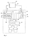
- the figure shows an exemplary test apparatus 10 that includes at least one call simulator 100 that can simulate an analog terminal 20 as a calling terminal and a terminal 30 as a called terminal.
- the analog terminal 20 is connected via an interface 42 to a mediating network node 40 to be tested.
- the terminal device 30, which in the present example is a digital terminal device, is connected to the switching network node 40 via an interface 44. Also conceivable is a test connection, in which the terminal device 30 is connected to another switching network node.
- the analogue terminal device 20 has a detector device 22, which can detect, inter alia, timing pulses generated by the network node 40. Furthermore, the analog terminal 20 has a hardware or software implemented time measuring device 24, which is able to measure time intervals between each two successive clock pulses.
- the schematically represented time measuring device 24 has, for example, N + 1 timers 24 1 to 24 N + 1 , with which N + 1 time-clock intervals can be measured. The measured time intervals are each assigned a consecutive number between 1 and N + 1 whose meaning is described below. The time intervals can be stored together with the associated number in a memory 26.
- the analog terminal 20 may further include a generator 29 which generates a loop break when a test connection to the analog terminal 20 is terminated.
- the terminal 30 includes a generator 32 for generating an event which signals the connection beginning and possibly the connection end of a test connection.
- a generator 32 for generating an event which signals the connection beginning and possibly the connection end of a test connection.
- the protocol message "connect” or “disconnect” is generated as an event, while a loop closure or a loop interruption is generated as event in an analog terminal device 30. These events are detected by a detector 34.
- the test apparatus 10 has a further time measuring device 50, which is connected to the detectors 22 and 34, for example. With the time measuring device 50, the time interval between the beginning of a test connection detected at the detector 34 and the first time-clock pulse detected at the detector 22 can be measured.
- a time measuring device 55 which can measure the time interval between the end of a test connection detected at the detector 22 or 34 and a clock pulse detected at the detector 22 which is generated in the network node 40 after termination of the test connection.
- the time measuring device 55 is connected to the detectors 22 and 34 for this purpose.
- the time measuring device 55 is connected to the time measuring device 24 in order to obtain the numbers of the measured time intervals and, if appropriate, the time length of certain time intervals.
- time correction values are stored, which are the systematic measurement errors between the interfaces 42 and 44 of the network node 40 as locations of the actual events - generation of timing pulses, detection of a connection end and beginning - and the detectors 22 and 34 as a location of the measured events correspond.
- a correction device 90 is connected to the memory device 26, the time measuring devices 50 and 55 and the memory device 80. Since the time intervals measured in the time measuring device 24 and stored in the memory device 26 need not be corrected, they are simply looped together with the associated number by the correction device 90 to an evaluation device 70. The values coming from the time measuring devices 50 and 55, on the other hand, are corrected in the correction device 90 by the systematic measurement errors stored in the memory device 80 and then transmitted to the evaluation device 70.
- the evaluation device 70 is further connected to a memory device 60 in which reference values are stored.
- the reference values correspond to the predetermined length of a time interval, which may depend on the selected test procedure, a predetermined time interval which may be between the actual start of connection and the generation of the first time-clock pulse, a further predetermined time interval defining the maximum time interval, which may be between the actual end of the test connection and the last time clock pulse generated thereafter, and a number y Timing pulses that may be generated maximally after the end of the test communication connection.
- a reference value for a number x of timing pulses which may be generated at least after the end of the test communication connection, may also be stored.
- test device 10 The mode of operation of the test device 10 shown in the figure will be explained in more detail below.
- test connection is to be made from the analog terminal 20 via the switching node 40 to the terminal 30.
- the analogue terminal 20 transmits inter alia the telephone number of the terminal device 30 to the network node, which then transmits call signaling to the terminal device 30.
- the network node 40 determines the contractual length of the time intervals which are relevant for the calculation of the connection costs. This length of this time interval interval is stored in the memory 60 as a reference value for the selected test connection.
- the lifting of the telephone receiver is simulated in the terminal device 30, for example.
- the protocol message "connect” generated in the generator 32 is transmitted to the interface 44 of the network node 40.
- the protocol message "connect” is first detected in the detector device 34, which then starts a time measurement by means of the time measuring device 50.
- the network node 40 In response to receiving the protocol message "connect" at the interface 44, the network node 40 sends a first timing pulse, the so-called start pulse Analog, calling Endinichtung 20.
- the detector 22 detects the received start pulse and stops the timer 50. Consequently, the measurement of the time interval between the generation of the protocol message "connect” and the reception of the start pulse at the analog terminal 20 is terminated.
- This start pulse (first count pulse) may deviate at most by a first predetermined period of time from the actual beginning of the connection.
- the time interval measured by the timer 50 is subject to a systematic measurement error.
- the systematic measurement error is due to the fact that the measurement points, ie locations in the analog terminal 20 and in the terminal 30, are not the locations of the actual events. Because the place where the start pulse actually sent and the start of connection (receiving the protocol message "connect") actually occurs, in the present example, the interfaces 42 and 44 of the network node 40.
- the time deviation caused by the falling apart of the places where the Events actually occur, and the measurement points at which these events are measured, represent the systematic measurement error, which is determined before the start of the test and stored in the memory 80.
- the systematic measurement error corresponds approximately to the signal transit time of the protocol message "connect" from the terminal device 30 to the network node 40 and the signal propagation time of the start pulse from the network node 40 to the analogue terminal device 20.
- the time measuring device 50 therefore supplies the measured time interval to the correction device 90, the time interval is corrected by the systematic measurement error.
- the corrected time interval is compared in the evaluation device 70 with the corresponding reference value from the memory 60 in order to be able to determine whether the time between the two events is at most the first predetermined time interval.
- the network node 40 continuously transmits timing pulses to the analog terminal 20, which are detected by the detector 22.
- the start pulse starts the first timer 24 1 of the timer 24, the next clock pulse stops the first timer 24 1 and starts the second timer, etc. until the last clock pulse received during the existing test connection stops the timer 24 N-1 and the timer 24 N starts.
- each measured time interval is assigned a consecutive number.
- the numbers and the associated time-clock intervals are stored in the memory device 26.
- a time-clock pulse following the measured connection end stops the timer 24 N and starts the timer 24 N + 1 .
- the timer 24 N + 1 may be stopped if no further clock pulse is received after the end of the test connection within a predetermined period of time, for example the length of two clock intervals.
- the content of the timer 24 N + 1 is then discarded.
- the time-clock intervals stored in the memory 26 are transmitted without correction together with the associated numbers via the correction device 90 to the evaluation device 70.
- a correction of the length of the time intervals is not required. This is due to the fact that the systematic measurement error in this test apparatus results, on the one hand, from the transit time of the timing pulses from the network node 40 to the analog terminal 20, and, on the other hand, from the processing speed of the test apparatus 10. Both leads to the fact that in the test apparatus 10 the event "network node 40 transmits time-clock pulse" is detected only with a time delay. This delay can be considered constant. Thus, the measurement of the interval length results in a systematic measurement error of ⁇ 0 ms.
- the evaluation device 70 compares the measured time intervals with the reference time interval stored in the memory 60 and checks whether the permissible tolerance is fulfilled.
- the test connection is terminated at the terminal device 30.
- the event "telephone receiver hooked up” is simulated in the terminal device 30.
- the generator 32 then transmits the protocol message "disconnect" to the interface 44 of the network node 40.
- the protocol message "disconnect” is detected by the detector 34, which then starts the time measuring device 55.
- the test apparatus 10 determines the number N of the currently active timer 24N .
- the value of the time measuring device 55 corresponds to the time interval between the generation of the protocol message "disconnect" and the reception of the one timing pulse.
- the measuring points in the analog terminal 20 and in the terminal 30 are not the locations of the actual events "connection end” and "generation of a timing pulse". Because the place where the clock pulse actually sent and the connection end (receiving the log message "disconnect") actually occurs, in the present example, the Interface 42 or 44 of the network node 40. The time deviation caused by the disintegration of the places where the events actually occur and the measurement points at which these events are measured represents a systematic measurement error occurring in the memory 80 is stored.
- the systematic measurement error in the present example corresponds approximately to the signal propagation time of the protocol message "disconnect" from the terminal 30 to the network node 40 and the signal propagation time of a timing pulse from the network node 40 to the analog terminal 20.
- the corrected value is transmitted together with the number N to the evaluation device 70 and compared there with the second predetermined time value to be able to determine whether the corrected value is less than or equal to the second predetermined time value.
- the evaluation device 70 can still check whether the number of time clock pulses occurring after the end of the test communication connection lies in the interval between x and y.
- a first clock pulse is detected by the detector 22 after the log message "disconnect" has been generated by the generator 32.
- the time measurement means 55 are stopped and the timer 24 N, while the timer is started 24 N +. 1
- the time interval N measured by the timer 24 N the sequence number N is assigned.
- a second clock pulse is detected by the detector 22.
- the timer 24 is stopped and the N + 1 by the timer 24 N + 1 measured timing interval, the serial number assigned to N + 1.
- the time measuring means 55 can recognize from the serial number of the timer 24 N + 1 that after the protocol message "disconnect" has been generated by the generator 32, a complete time interval N + 1 has been measured and adds this value to the value of the time measuring device 55, which corresponds to the time interval between the generation of the protocol message "disconnect" and the reception of the first clock pulse.
- the time interval determined in the time measuring device 55 is corrected in the correction device 90 by the systematic measurement error which is stored in the memory device 80 and transmitted together with the number N to the evaluation device 70.
- the evaluation device 70 checks whether the calculated value is less than or equal to the second predetermined period of time.
- the evaluation device 70 can still check whether the number of time clock pulses occurring after the end of the test communication connection lies in the interval between x and y.
- the number of the currently running timer of the time measuring device 24 must be registered by the testing device 10 in order to be able to carry out the described evaluation of the measurement results.
- the location of the measuring points is preferably selected so that the associated systematic measuring error becomes as low as possible.
- the measuring point in which the event "connection start” is detected in the called terminal 30.
- the measuring point in which the event "connection end” is detected is also in the terminal 30, to which the connection has ended.
Landscapes
- Engineering & Computer Science (AREA)
- Signal Processing (AREA)
- Computer Networks & Wireless Communication (AREA)
- Computer Security & Cryptography (AREA)
- Monitoring And Testing Of Exchanges (AREA)
- Meter Arrangements (AREA)
- Telephone Function (AREA)
- Telephonic Communication Services (AREA)
- Data Exchanges In Wide-Area Networks (AREA)
- Facsimiles In General (AREA)
- Maintenance And Management Of Digital Transmission (AREA)
Claims (15)
- Procédé de vérification de la taxation d'une communication selon des intervalles d'impulsions d'horloge, un dispositif de vérification (10) pouvant simuler au moins un terminal analogique appelant (20) et au moins un terminal appelé (30) étant connecté à au moins un noeud de réseau (40) apte à produire des impulsions d'horloge, ledit procédé comportant les étapes suivantes :- établissement et coupure d'au moins une communication d'essai prédéterminée par l'intermédiaire d'au moins un noeud de réseau (40) ;- détermination de l'écart temporel entre le début de la communication d'essai et la production d'une première impulsion d'horloge et vérification si l'écart temporel obtenu se situe à l'intérieur d'une première plage temporelle prédéterminée ;- pendant la durée de la communication d'essai, mesure et comparaison à un intervalle de temps prédéterminé d'intervalles d'impulsions d'horloge successives ; et- vérification si, à la fin de la communication d'essai, au moins une autre impulsion d'horloge a été reçue, dans l'affirmative, détermination de l'écart temporel entre la fin de la communication d'essai et la au moins une impulsion d'horloge et vérification si l'écart temporel obtenu se situe à l'intérieur d'une seconde plage temporelle prédéterminée.
- Procédé selon la revendication 1,
caractérisé en ce qu'on vérifie en plus si le nombre des impulsions d'horloge apparues après la fin de la communication d'essai est plus petit, plus grand ou égal à un nombre y maximal prédéterminé d'impulsions d'horloge. - Procédé selon la revendication 1 ou 2,
caractérisé en ce que l'écart temporel entre le début de la communication d'essai et la production de la première impulsion d'horloge est déterminé selon les étapes suivantes :- détection, au niveau d'un premier point de mesure (34) prédéterminé du dispositif de vérification (10), de l'apparition d'un premier évènement prédéterminé, notamment d'un signal CONNECT ou d'une fermeture de boucle, qui correspond au début mesurable de la communication d'essai ;- détection, au niveau d'un second point de mesure (22) prédéterminé du dispositif de vérification, de la réception de la première impulsion d'horloge de la communication d'essai produite par le noeud de réseau (40) ; et- démarrage et arrêt d'une mesure du temps (50) en fonction de l'apparition détectée du premier évènement prédéterminé, notamment d'un signal CONNECT ou d'une fermeture de boucle, et de la réception de la première impulsion d'horloge. - Procédé selon la revendication 3,
caractérisé en ce qu'on détermine l'erreur de mesure systématique entre l'endroit (44) de l'apparition effective du début de la communication d'essai et le premier point de mesure (34) du dispositif de vérification (10), en ce qu'on détermine l'erreur de mesure systématique entre l'endroit (42) de la production effective de la première impulsion d'horloge et le second point de mesure du dispositif de vérification (10), en ce qu'on mesure l'écart temporel entre l'apparition détectée du premier évènement prédéterminé et la réception de la première impulsion d'horloge, en ce qu'on corrige ledit écart temporel de la valeur des erreurs de mesure systématiques, et en ce qu'on vérifie si l'écart temporel corrigé se situe à l'intérieur de la première plage temporelle prédéterminée. - Procédé selon l'une quelconque des revendications 1 à 4,
caractérisé en ce qu'on mesure les intervalles d'impulsions d'horloge successives selon les étapes suivantes :- la première impulsion d'horloge qui arrive au terminal analogique appelant (20) démarre une première mesure du temps (241),- chacune des impulsions d'horloge suivantes arrivant au terminal analogique appelant arrête la mesure du temps démarrée par l'impulsion d'horloge immédiatement précédente et démarre une nouvelle mesure du temps ;- la dernière impulsion d'horloge de la communication d'essai démarre une i-ième mesure du temps (24i). - Procédé selon la revendication 5,
caractérisé en ce qu'un numéro d'ordre est affecté à chaque mesure du temps démarrée. - Procédé selon la revendication 6,
caractérisé en ce qu'on détermine l'écart temporel entre la fin de la communication d'essai et une première impulsion d'horloge reçue après la fin de la communication d'essai selon les étapes suivantes :- démarrage d'une mesure du temps (55) à l'apparition, au niveau du premier ou du second point de mesure prédéterminé (34) du dispositif de vérification (10), d'un second évènement prédéterminé, notamment d'un signal DISCONNECT ou d'une interruption de boucle, qui correspond à la fin mesurable de la communication d'essai ;- arrêt de la mesure du temps (55) démarrée par le second évènement prédéterminé, à la réception par le second point de mesure prédéterminé du dispositif de vérification de la première impulsion d'horloge après la fin de la communication d'essai ; et- comparaison de la valeur de la mesure du temps (55) à la seconde plage temporelle prédéterminée. - Procédé selon la revendication 7,
caractérisé en ce qu'on détermine, à l'apparition, au niveau du premier ou du second point de mesure prédéterminé (34 ; 22) du dispositif de vérification (10), du second évènement prédéterminé, notamment d'un signal DISCONNECT ou d'une interruption de boucle, le numéro de la mesure du temps (24) en cours de l'intervalle de deux impulsions d'horloge successives ;
en ce qu'on détermine l'écart temporel entre la fin de la communication d'essai et d'autres impulsions d'horloge détectées après la fin de la communication d'essai selon les étapes suivantes :addition de la valeur de la mesure du temps (55) pour déterminer l'écart temporel entre la fin de la communication d'essai et la première impulsion d'horloge reçue après la fin de la communication d'essai et de celles de l'ensemble des mesures du temps (241-24i) pour déterminer les intervalles d'impulsions d'horloge successives dont les numéros respectifs sont plus grands que le numéro de la mesure du temps détecté à l'apparition, au niveau du premier ou du second point de mesure prédéterminé (34 ; 22) du dispositif de vérification (10), du second évènement prédéterminé, notamment d'un signal DISCONNECT ou d'une interruption de boucle et comparaison desdites valeurs à la seconde plage temporelle prédéterminée. - Procédé selon la revendication 7 ou 8,
caractérisé en ce qu'on détermine l'erreur de mesure systématique entre l'endroit (42, 44) de l'apparition effective de la fin de la communication d'essai et le premier et/ou le second point de mesure du dispositif de vérification (10) et l'erreur de mesure systématique entre l'endroit (42) de la production effective d'impulsions d'horloge et le second point de mesure du dispositif de vérification (10),
en ce qu'on mesure l'écart temporel entre l'apparition du second évènement prédéterminé, notamment d'un signal DISCONNECT ou d'une interruption de boucle, et la réception de la première impulsion d'horloge apparue après la fin de la communication d'essai et on corrige ledit écart temporel de la valeur des erreurs de mesure systématiques. - Procédé selon l'une quelconque des revendications 3 à 9,
caractérisé en ce que le premier point de mesure est défini par le terminal appelé (30), et en ce que le second point de mesure est défini par le terminal analogique appelant (20), la communication d'essai pouvant être coupée au niveau des deux terminaux (20, 30). - Dispositif de vérification destiné à être connecté à au moins un noeud de réseau (40) à vérifier et apte à émettre des impulsions d'horloge, notamment pour la mise en oeuvre d'un procédé selon l'une quelconque des revendications 1 à 10, comportant un simulateur d'appel (100) pour simuler au moins un terminal analogique appelant (20) et pour simuler au moins un autre terminal (30) apte à fonctionner comme terminal appelé, un premier dispositif de détection (22) pour détecter des impulsions d'horloge,
un second dispositif de détection (34) pour détecter un premier évènement prédéterminé, notamment un signal CONNECT ou une fermeture de boucle, qui correspond au début mesurable d'une communication d'essai,
le premier et/ou le second dispositif de détection (22 ; 34) étant réalisés pour détecter un second évènement prédéterminé, notamment un signal de DISCONNECT ou une interruption de boucle, qui correspond à la fin mesurable d'une communication d'essai, un premier dispositif de mesure du temps (24) pour mesurer des intervalles d'impulsions d'horloge de deux impulsions d'horloge successives respectivement,
un deuxième dispositif de mesure du temps (50) pour mesurer l'écart temporel entre l'apparition du premier évènement prédéterminé et la réception de la première impulsion d'horloge d'une communication d'essai établie,
un troisième dispositif de mesure du temps (55) pour mesurer l'écart temporel entre l'apparition du second évènement prédéterminé et la réception d'au moins une impulsion d'horloge après la fin mesurée de la communication d'essai,
un dispositif d'évaluation (70) pour comparer les temps mesurés par les dispositifs de mesure du temps respectifs à des plages temporelles correspondantes prédéterminées. - Dispositif de vérification selon la revendication 11,
caractérisé en ce que le dispositif d'évaluation (70) est réalisé de manière à vérifier si le nombre des impulsions d'horloge apparues après la fin de la communication d'essai est plus petit, plus grand ou égal à un nombre y maximal prédéterminé d'impulsions d'horloge. - Dispositif de vérification selon la revendication 11 ou 12,
caractérisé par un dispositif de mémoire (80) dans lequel est stockée l'erreur de mesure systématique entre l'endroit (44) du début effectif d'une communication d'essai et le second dispositif de détection (34), dans lequel est stockée l'erreur de mesure systématique entre l'endroit (42, 44) de la fin effective d'une communication d'essai et le premier ou le second dispositif de détection (22 ; 34), et dans lequel est stockée l'erreur de mesure systématique entre l'endroit (42) de la production effective d'impulsions d'horloge et le premier dispositif de détection (22) du dispositif de vérification (10),
un dispositif de correction (90) relié au dispositif de mémoire (80) pour corriger les valeurs mesurées par le premier, le deuxième et le troisième dispositif de mesure du temps (24, 50, 55) de la valeur respective de l'erreur de mesure systématique,
le dispositif d'évaluation (70) comportant des plages temporelles prédéterminées correspondantes pour comparer les temps mesurés aux temps corrigés. - Dispositif de vérification selon l'une quelconque des revendications 11 à 13,
caractérisé en ce qu'un dispositif de numérotation en continu d'intervalles d'impulsions d'horloge successifs est prévu,
en ce que le troisième dispositif de mesure du temps (55) peut détecter, en réponse aux numéros affectés aux intervalles d'impulsions d'horloge, si un intervalle d'impulsion d'horloge a été mesuré dans le premier dispositif de mesure du temps (24) après la détection du second évènement prédéterminé, notamment d'un signal DISCONNECT ou d'une interruption de boucle,
et en ce que le troisième dispositif de mesure du temps (55) ou le dispositif d'évaluation (70) peut additionner la valeur de l'écart temporel entre la fin de la communication d'essai et la première impulsion d'horloge reçue après la fin de la communication d'essai et celles de l'ensemble des intervalles d'impulsions d'horloge mesurés dont les numéros sont plus grands que le numéro en cours de l'intervalle d'impulsions d'horloge mesuré à l'apparition, au niveau du premier ou du second dispositif de détection (22, 34) du dispositif de vérification (10), du second évènement prédéterminé, notamment d'un signal DISCONNECT ou d'une interruption de boucle. - Dispositif de vérification selon l'une quelconque des revendications 11 à 14,
caractérisé en ce que le premier dispositif de détection (22) est affecté au terminal analogique appelant (20) et en ce que le second dispositif de détection (34) est affecté au terminal appelé (34).
Applications Claiming Priority (3)
| Application Number | Priority Date | Filing Date | Title |
|---|---|---|---|
| DE10251143A DE10251143A1 (de) | 2002-10-31 | 2002-10-31 | Verfahren und Prüfvorrichtung zum Überprüfen für eine Kommunikationsverbindung nach Zeittaktintervallen |
| DE10251143 | 2002-10-31 | ||
| PCT/DE2003/002394 WO2004040888A1 (fr) | 2002-10-31 | 2003-07-17 | Procede et dispositif de verification utilises pour verifier la taxation d'une communication selon des intervalles d'impulsions d'horloge |
Publications (2)
| Publication Number | Publication Date |
|---|---|
| EP1559263A1 EP1559263A1 (fr) | 2005-08-03 |
| EP1559263B1 true EP1559263B1 (fr) | 2007-10-31 |
Family
ID=32103277
Family Applications (1)
| Application Number | Title | Priority Date | Filing Date |
|---|---|---|---|
| EP03809699A Expired - Lifetime EP1559263B1 (fr) | 2002-10-31 | 2003-07-17 | Procede et dispositif de verification utilises pour verifier la taxation d'une communication selon des intervalles d'impulsions d'horloge |
Country Status (7)
| Country | Link |
|---|---|
| US (1) | US7920683B2 (fr) |
| EP (1) | EP1559263B1 (fr) |
| JP (1) | JP4335810B2 (fr) |
| AT (1) | ATE377324T1 (fr) |
| CA (1) | CA2498955A1 (fr) |
| DE (2) | DE10251143A1 (fr) |
| WO (1) | WO2004040888A1 (fr) |
Families Citing this family (1)
| Publication number | Priority date | Publication date | Assignee | Title |
|---|---|---|---|---|
| US9031221B2 (en) * | 2009-12-22 | 2015-05-12 | Cyara Solutions Pty Ltd | System and method for automated voice quality testing |
Family Cites Families (9)
| Publication number | Priority date | Publication date | Assignee | Title |
|---|---|---|---|---|
| CH593594A5 (fr) * | 1975-07-31 | 1977-12-15 | Stoppani Sa | |
| FR2340001A1 (fr) * | 1976-01-27 | 1977-08-26 | Hugon Jean | Appareil automatique pour l'impression des donnees de numerotation et de taxation afferentes a une communication telephonique |
| FR2420258A1 (fr) | 1978-03-14 | 1979-10-12 | Serres Bernard | Appareil analyseur de trafic de postes telephoniques publics |
| JPS5857832A (ja) * | 1981-09-30 | 1983-04-06 | Fujitsu Ltd | 課金信号中継方式 |
| FR2538198A1 (fr) | 1982-12-20 | 1984-06-22 | Hezard Pierre | Appareil pour surveiller la taxation d'un central telephonique |
| FR2541541A1 (fr) | 1983-02-23 | 1984-08-24 | Trublin Roger | Systeme emetteur d'impulsions periodiques de taxation pour centres telephoniques |
| GB8808623D0 (en) * | 1988-04-12 | 1988-05-11 | British Telecomm | Customer line tester |
| NL9300036A (nl) * | 1993-01-08 | 1994-08-01 | Nederland Ptt | Systeem voor het testen van de gebruiksregistratie-functie in een telecommunicatiesysteem. |
| DE10056523B4 (de) * | 2000-11-15 | 2006-06-01 | Tenovis Gmbh & Co. Kg | Verfahren zum Erzeugen von Gebühreninformationen in einem Telekommunikationsnetz |
-
2002
- 2002-10-31 DE DE10251143A patent/DE10251143A1/de not_active Withdrawn
-
2003
- 2003-07-17 JP JP2004547376A patent/JP4335810B2/ja not_active Expired - Fee Related
- 2003-07-17 EP EP03809699A patent/EP1559263B1/fr not_active Expired - Lifetime
- 2003-07-17 DE DE50308510T patent/DE50308510D1/de not_active Expired - Lifetime
- 2003-07-17 AT AT03809699T patent/ATE377324T1/de not_active IP Right Cessation
- 2003-07-17 US US10/533,457 patent/US7920683B2/en not_active Expired - Fee Related
- 2003-07-17 WO PCT/DE2003/002394 patent/WO2004040888A1/fr not_active Ceased
- 2003-07-17 CA CA002498955A patent/CA2498955A1/fr not_active Abandoned
Also Published As
| Publication number | Publication date |
|---|---|
| ATE377324T1 (de) | 2007-11-15 |
| CA2498955A1 (fr) | 2004-05-13 |
| DE50308510D1 (de) | 2007-12-13 |
| US7920683B2 (en) | 2011-04-05 |
| JP2006505162A (ja) | 2006-02-09 |
| DE10251143A1 (de) | 2004-05-13 |
| US20060109963A1 (en) | 2006-05-25 |
| JP4335810B2 (ja) | 2009-09-30 |
| WO2004040888A1 (fr) | 2004-05-13 |
| EP1559263A1 (fr) | 2005-08-03 |
Similar Documents
| Publication | Publication Date | Title |
|---|---|---|
| DE3047239C2 (de) | Verfahren und Schaltungsanordnung zum Messen der Güte digitaler Übertragungsstrecken und -einrichtungen | |
| DE2741214B2 (de) | Schaltungsanordnung für eine zyklisch arbeitende elektronische Empfangs-, Verkehrsmeß-, Auswerte- und Registriereinrichtung in Fernmelde-, insbesondere Fernsprechvermittlungsanlagen | |
| DE2442507A1 (de) | Anordnung und verfahren zur rahmensynchronisierung | |
| DE19726539C2 (de) | Verfahren und Schaltungsanordnung zur Lokalisierung eines Kurzschluß oder Kabelbruchs in einem Bus-System | |
| EP1559263B1 (fr) | Procede et dispositif de verification utilises pour verifier la taxation d'une communication selon des intervalles d'impulsions d'horloge | |
| DE2714238C2 (de) | Überwachungsanordnung für eine Gruppe von Vorrichtungen | |
| EP0354214B1 (fr) | Procede de determination de la duree electrique de trajets de signaux | |
| EP1552673B1 (fr) | Systeme et procede de controle des donnees de connexion en fonction du temps, detectees par un noeud reseau | |
| EP1221245B1 (fr) | Systeme, dispositif d'evaluation et procede de verification des donnees de communication relatives a une liaison, detectees par un central numerique | |
| EP0306736A2 (fr) | Procédé pour la transmission d'information de connexion mémorisée dans une installation de commutation de communications vers une installation de traitement d'information | |
| DE2801333B2 (de) | Empfangsschaltung für Echosignale in einer Echolotanlage | |
| DE3743959A1 (de) | Verfahren zur ueberpruefung betriebstechnischer funktionen einer rechnergesteuerten kommunikationsvermittlungsanlage | |
| DE102006032961A1 (de) | Verfahren und System zur Ermittlung der Abhängigkeit zwischen Geräteparametern eines Mobilfunkgeräts und Signalgrößen | |
| DE3527827C2 (fr) | ||
| EP0508070B1 (fr) | Méthode et dispositif de reconnaissance de perte de synchronisation entre deux suites de mots d'un signal de référence et d'un signal de mesure | |
| DE1927682C (de) | Schaltungsanordnung zum Prüfen von Gebuhrenmittlungsvorrichtungen in Fernmel de , insbesondere Fernschreibvermittlungs anlagen | |
| DE2553258C3 (de) | Schaltungsanordnung für einen digitalen Mehrfrequenz-Zeichenempfänger | |
| DE3239921C1 (de) | Überwachungsverfahren für Sensoren zur Nachrichtenverkehrserfassung | |
| DE2721764B1 (de) | Bitfehlerquotenbestimmung in PCM-UEbertragungssystemen | |
| DE3205172C1 (de) | Verfahren zum Ermitteln der Verkehrsbelastung von zentralen Steuereinrichtungen in Fernmelde-, insbesondere Fernsprechanlagen | |
| DE2943513C2 (de) | Verfahren und Schaltungsanordnung zum Anzeigen einer Nachzahlaufforderung bei Münzfernsprechern | |
| DE3121169C2 (de) | Verfahren zur Prüfung von Echosperren | |
| DE3718114A1 (de) | Verfahren zur feststellung der elektrischen laufzeit von signalstrecken | |
| DE1927682B2 (de) | Schaltungsanordnung zum pruefen von gebuehrenermittlungsvorrichtungen in fernmelde-, insbesondere fernschreibvermittlungsanlagen | |
| DE4334204A1 (de) | Verfahren und Anordnung zur Zeichenregeneration von UART-Zeichen |
Legal Events
| Date | Code | Title | Description |
|---|---|---|---|
| PUAI | Public reference made under article 153(3) epc to a published international application that has entered the european phase |
Free format text: ORIGINAL CODE: 0009012 |
|
| 17P | Request for examination filed |
Effective date: 20050531 |
|
| AK | Designated contracting states |
Kind code of ref document: A1 Designated state(s): AT BE BG CH CY CZ DE DK EE ES FI FR GB GR HU IE IT LI LU MC NL PT RO SE SI SK TR |
|
| AX | Request for extension of the european patent |
Extension state: AL LT LV MK |
|
| DAX | Request for extension of the european patent (deleted) | ||
| GRAP | Despatch of communication of intention to grant a patent |
Free format text: ORIGINAL CODE: EPIDOSNIGR1 |
|
| GRAS | Grant fee paid |
Free format text: ORIGINAL CODE: EPIDOSNIGR3 |
|
| GRAA | (expected) grant |
Free format text: ORIGINAL CODE: 0009210 |
|
| AK | Designated contracting states |
Kind code of ref document: B1 Designated state(s): AT BE BG CH CY CZ DE DK EE ES FI FR GB GR HU IE IT LI LU MC NL PT RO SE SI SK TR |
|
| REG | Reference to a national code |
Ref country code: GB Ref legal event code: FG4D Free format text: NOT ENGLISH |
|
| REG | Reference to a national code |
Ref country code: IE Ref legal event code: FG4D Free format text: LANGUAGE OF EP DOCUMENT: GERMAN |
|
| REG | Reference to a national code |
Ref country code: CH Ref legal event code: EP |
|
| REF | Corresponds to: |
Ref document number: 50308510 Country of ref document: DE Date of ref document: 20071213 Kind code of ref document: P |
|
| GBT | Gb: translation of ep patent filed (gb section 77(6)(a)/1977) |
Effective date: 20080123 |
|
| NLV1 | Nl: lapsed or annulled due to failure to fulfill the requirements of art. 29p and 29m of the patents act | ||
| PG25 | Lapsed in a contracting state [announced via postgrant information from national office to epo] |
Ref country code: ES Free format text: LAPSE BECAUSE OF FAILURE TO SUBMIT A TRANSLATION OF THE DESCRIPTION OR TO PAY THE FEE WITHIN THE PRESCRIBED TIME-LIMIT Effective date: 20080211 Ref country code: SE Free format text: LAPSE BECAUSE OF FAILURE TO SUBMIT A TRANSLATION OF THE DESCRIPTION OR TO PAY THE FEE WITHIN THE PRESCRIBED TIME-LIMIT Effective date: 20080131 Ref country code: NL Free format text: LAPSE BECAUSE OF FAILURE TO SUBMIT A TRANSLATION OF THE DESCRIPTION OR TO PAY THE FEE WITHIN THE PRESCRIBED TIME-LIMIT Effective date: 20071031 |
|
| PG25 | Lapsed in a contracting state [announced via postgrant information from national office to epo] |
Ref country code: PT Free format text: LAPSE BECAUSE OF FAILURE TO SUBMIT A TRANSLATION OF THE DESCRIPTION OR TO PAY THE FEE WITHIN THE PRESCRIBED TIME-LIMIT Effective date: 20080331 Ref country code: BG Free format text: LAPSE BECAUSE OF FAILURE TO SUBMIT A TRANSLATION OF THE DESCRIPTION OR TO PAY THE FEE WITHIN THE PRESCRIBED TIME-LIMIT Effective date: 20080131 Ref country code: SI Free format text: LAPSE BECAUSE OF FAILURE TO SUBMIT A TRANSLATION OF THE DESCRIPTION OR TO PAY THE FEE WITHIN THE PRESCRIBED TIME-LIMIT Effective date: 20071031 |
|
| REG | Reference to a national code |
Ref country code: IE Ref legal event code: FD4D |
|
| ET | Fr: translation filed | ||
| PG25 | Lapsed in a contracting state [announced via postgrant information from national office to epo] |
Ref country code: CZ Free format text: LAPSE BECAUSE OF FAILURE TO SUBMIT A TRANSLATION OF THE DESCRIPTION OR TO PAY THE FEE WITHIN THE PRESCRIBED TIME-LIMIT Effective date: 20071031 Ref country code: DK Free format text: LAPSE BECAUSE OF FAILURE TO SUBMIT A TRANSLATION OF THE DESCRIPTION OR TO PAY THE FEE WITHIN THE PRESCRIBED TIME-LIMIT Effective date: 20071031 |
|
| PG25 | Lapsed in a contracting state [announced via postgrant information from national office to epo] |
Ref country code: RO Free format text: LAPSE BECAUSE OF FAILURE TO SUBMIT A TRANSLATION OF THE DESCRIPTION OR TO PAY THE FEE WITHIN THE PRESCRIBED TIME-LIMIT Effective date: 20071031 Ref country code: SK Free format text: LAPSE BECAUSE OF FAILURE TO SUBMIT A TRANSLATION OF THE DESCRIPTION OR TO PAY THE FEE WITHIN THE PRESCRIBED TIME-LIMIT Effective date: 20071031 |
|
| PLBE | No opposition filed within time limit |
Free format text: ORIGINAL CODE: 0009261 |
|
| STAA | Information on the status of an ep patent application or granted ep patent |
Free format text: STATUS: NO OPPOSITION FILED WITHIN TIME LIMIT |
|
| 26N | No opposition filed |
Effective date: 20080801 |
|
| PG25 | Lapsed in a contracting state [announced via postgrant information from national office to epo] |
Ref country code: IE Free format text: LAPSE BECAUSE OF FAILURE TO SUBMIT A TRANSLATION OF THE DESCRIPTION OR TO PAY THE FEE WITHIN THE PRESCRIBED TIME-LIMIT Effective date: 20071031 |
|
| PG25 | Lapsed in a contracting state [announced via postgrant information from national office to epo] |
Ref country code: GR Free format text: LAPSE BECAUSE OF FAILURE TO SUBMIT A TRANSLATION OF THE DESCRIPTION OR TO PAY THE FEE WITHIN THE PRESCRIBED TIME-LIMIT Effective date: 20080201 |
|
| PG25 | Lapsed in a contracting state [announced via postgrant information from national office to epo] |
Ref country code: FI Free format text: LAPSE BECAUSE OF FAILURE TO SUBMIT A TRANSLATION OF THE DESCRIPTION OR TO PAY THE FEE WITHIN THE PRESCRIBED TIME-LIMIT Effective date: 20071031 |
|
| REG | Reference to a national code |
Ref country code: CH Ref legal event code: PL |
|
| PG25 | Lapsed in a contracting state [announced via postgrant information from national office to epo] |
Ref country code: MC Free format text: LAPSE BECAUSE OF NON-PAYMENT OF DUE FEES Effective date: 20080731 |
|
| PG25 | Lapsed in a contracting state [announced via postgrant information from national office to epo] |
Ref country code: EE Free format text: LAPSE BECAUSE OF FAILURE TO SUBMIT A TRANSLATION OF THE DESCRIPTION OR TO PAY THE FEE WITHIN THE PRESCRIBED TIME-LIMIT Effective date: 20071031 |
|
| PG25 | Lapsed in a contracting state [announced via postgrant information from national office to epo] |
Ref country code: LI Free format text: LAPSE BECAUSE OF NON-PAYMENT OF DUE FEES Effective date: 20080731 Ref country code: CH Free format text: LAPSE BECAUSE OF NON-PAYMENT OF DUE FEES Effective date: 20080731 |
|
| PG25 | Lapsed in a contracting state [announced via postgrant information from national office to epo] |
Ref country code: CY Free format text: LAPSE BECAUSE OF FAILURE TO SUBMIT A TRANSLATION OF THE DESCRIPTION OR TO PAY THE FEE WITHIN THE PRESCRIBED TIME-LIMIT Effective date: 20071031 |
|
| PG25 | Lapsed in a contracting state [announced via postgrant information from national office to epo] |
Ref country code: AT Free format text: LAPSE BECAUSE OF NON-PAYMENT OF DUE FEES Effective date: 20080717 |
|
| PG25 | Lapsed in a contracting state [announced via postgrant information from national office to epo] |
Ref country code: BE Free format text: LAPSE BECAUSE OF NON-PAYMENT OF DUE FEES Effective date: 20080731 Ref country code: LU Free format text: LAPSE BECAUSE OF NON-PAYMENT OF DUE FEES Effective date: 20080717 Ref country code: HU Free format text: LAPSE BECAUSE OF FAILURE TO SUBMIT A TRANSLATION OF THE DESCRIPTION OR TO PAY THE FEE WITHIN THE PRESCRIBED TIME-LIMIT Effective date: 20080501 |
|
| PG25 | Lapsed in a contracting state [announced via postgrant information from national office to epo] |
Ref country code: TR Free format text: LAPSE BECAUSE OF FAILURE TO SUBMIT A TRANSLATION OF THE DESCRIPTION OR TO PAY THE FEE WITHIN THE PRESCRIBED TIME-LIMIT Effective date: 20071031 |
|
| PG25 | Lapsed in a contracting state [announced via postgrant information from national office to epo] |
Ref country code: IT Free format text: LAPSE BECAUSE OF NON-PAYMENT OF DUE FEES Effective date: 20080731 |
|
| PGFP | Annual fee paid to national office [announced via postgrant information from national office to epo] |
Ref country code: FR Payment date: 20110729 Year of fee payment: 9 |
|
| PGFP | Annual fee paid to national office [announced via postgrant information from national office to epo] |
Ref country code: DE Payment date: 20110926 Year of fee payment: 9 Ref country code: GB Payment date: 20110721 Year of fee payment: 9 |
|
| GBPC | Gb: european patent ceased through non-payment of renewal fee |
Effective date: 20120717 |
|
| REG | Reference to a national code |
Ref country code: FR Ref legal event code: ST Effective date: 20130329 |
|
| PG25 | Lapsed in a contracting state [announced via postgrant information from national office to epo] |
Ref country code: FR Free format text: LAPSE BECAUSE OF NON-PAYMENT OF DUE FEES Effective date: 20120731 Ref country code: DE Free format text: LAPSE BECAUSE OF NON-PAYMENT OF DUE FEES Effective date: 20130201 Ref country code: GB Free format text: LAPSE BECAUSE OF NON-PAYMENT OF DUE FEES Effective date: 20120717 |
|
| REG | Reference to a national code |
Ref country code: DE Ref legal event code: R119 Ref document number: 50308510 Country of ref document: DE Effective date: 20130201 |